
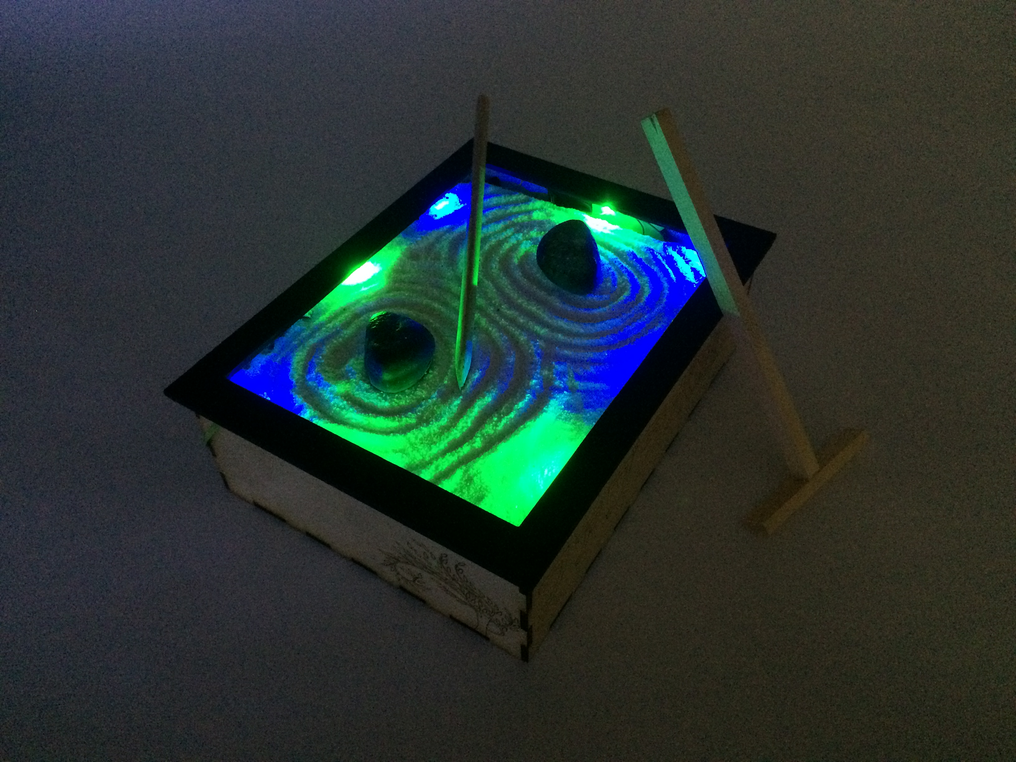
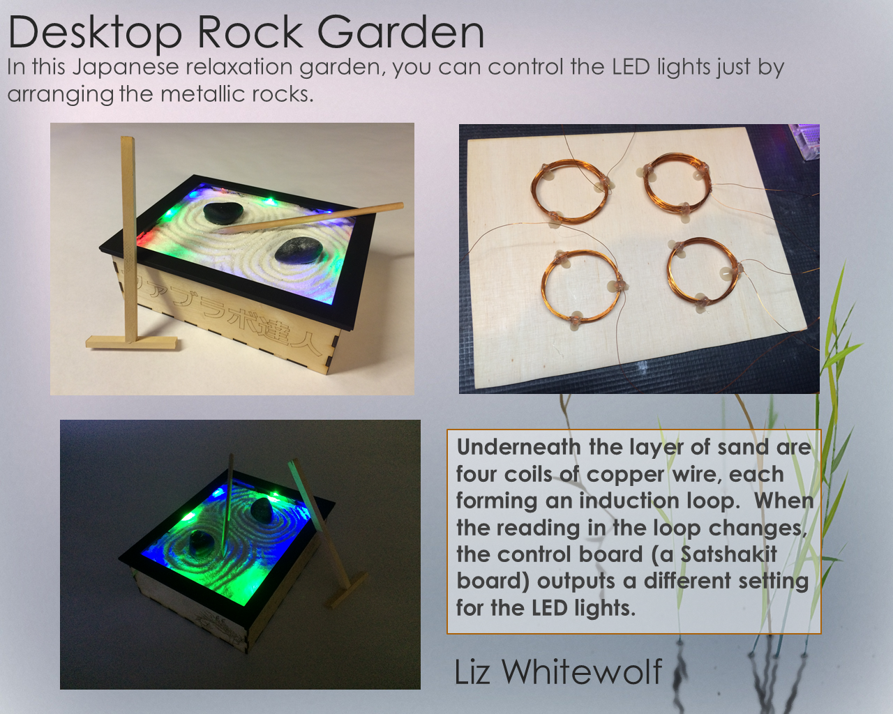
My final project is a desktop zen garden that has LED strips along the edges and it is programmed to change colors slowly based on where the rocks are placed in the garden itself.
In this video clip, the LED lights slowly change from red/blue to green/blue when the rocks are moved to different spots on the coil.
I worked on parts of my final project through some of the assignment weeks.
INDUCTANCE_COIL_LOOPS
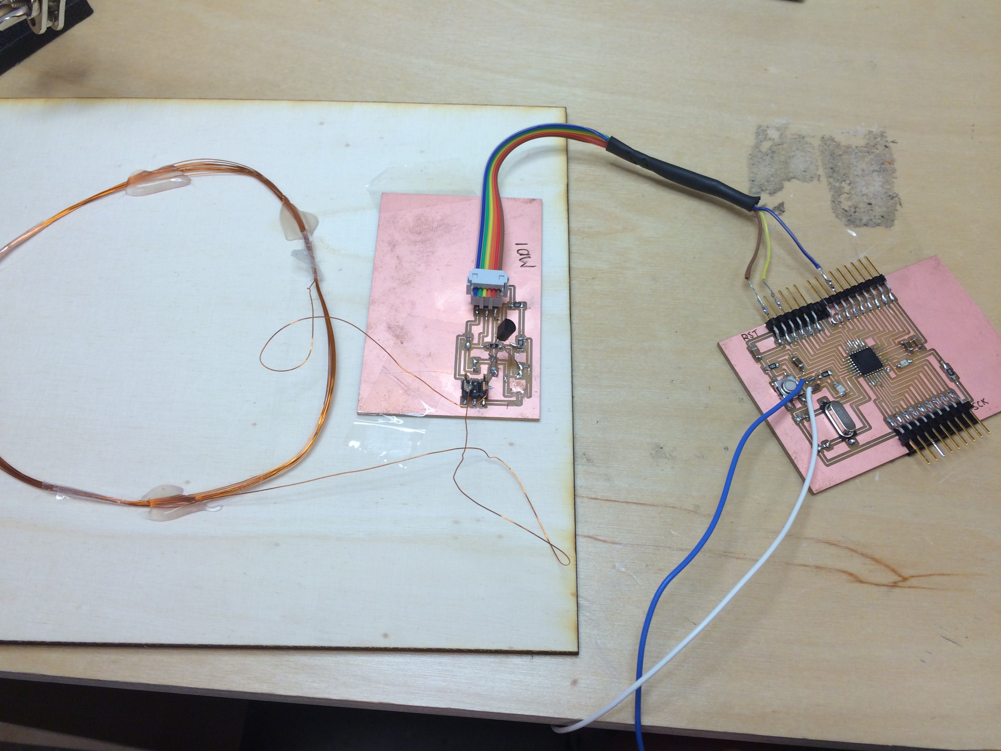
From my initial assignment for input devices when I designed 4 inductance coils to use for my Desktop Zen Garden, I had to make some changes. In moving the sensor system from a breadboard to a milled surface mount board, I had an issue. I didn't have enough of the resonators that I needed, in fact I only had one. So, instead of four different loops of coil for my final project, I tried it with just one loop of coil. I made one inductance coil board and ran it off of my modified Satshakit board, which is detailed in my out put devices page. . This cut down on the wiring issues and simplified the programming significantly, as I just commented out the parts of the code for the additional loops.
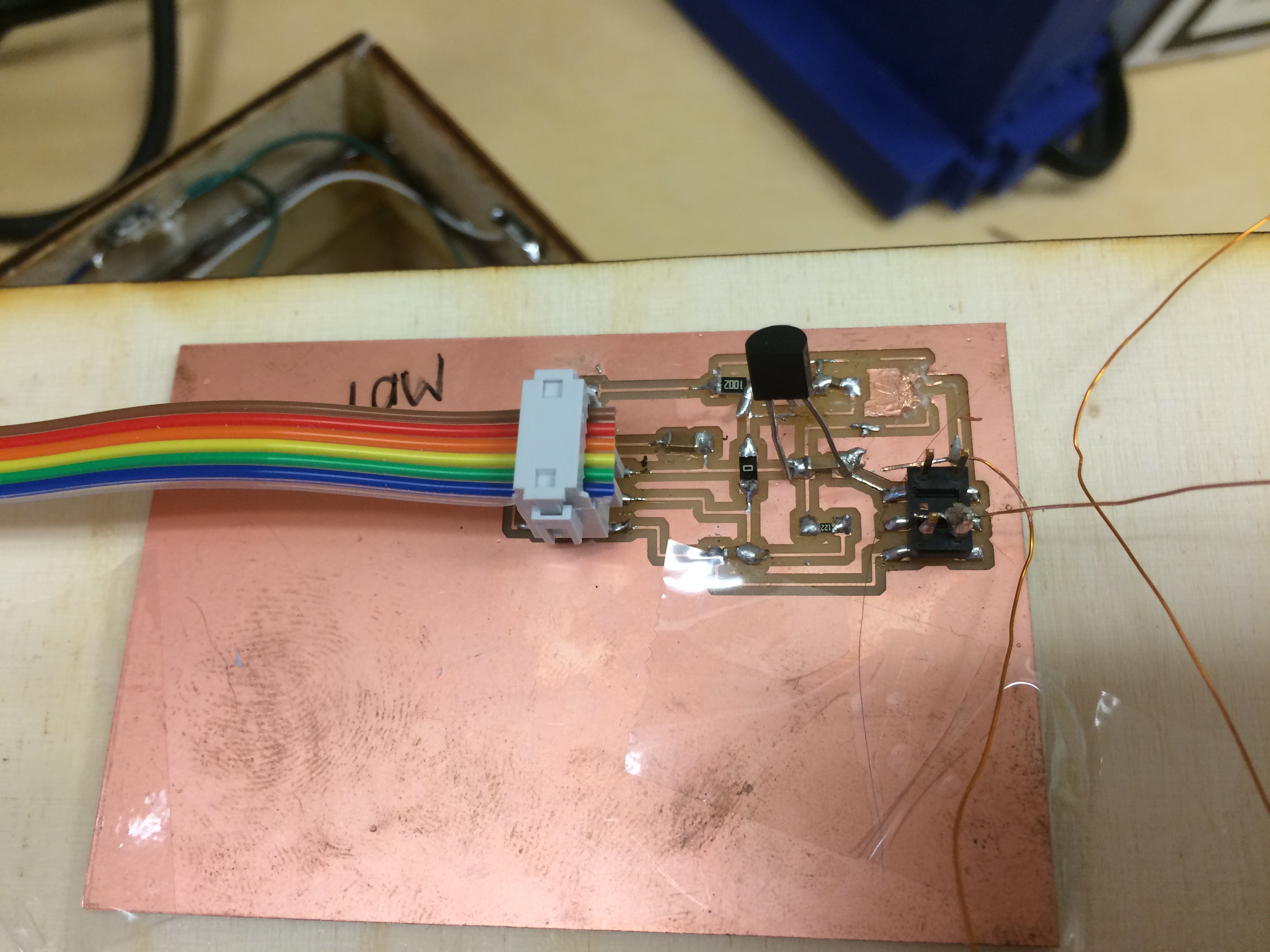
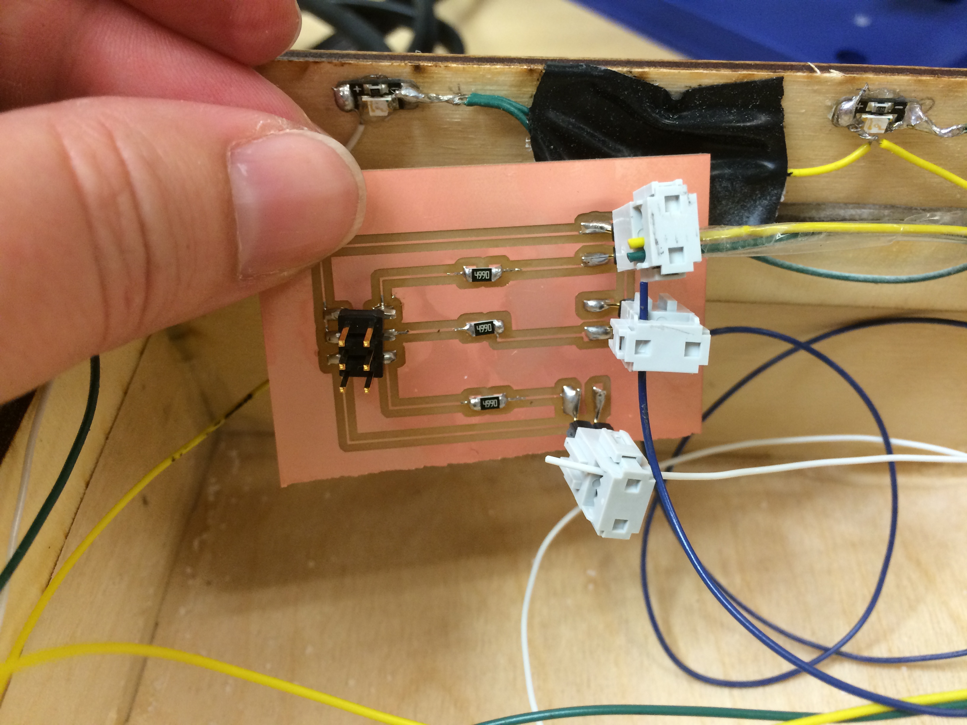
Here is my sensor board from my coil. The two copper wire pieces are each end of my inductance coil. I soldered them directly onto the pin headers of the board.
LED_OUTPUTS
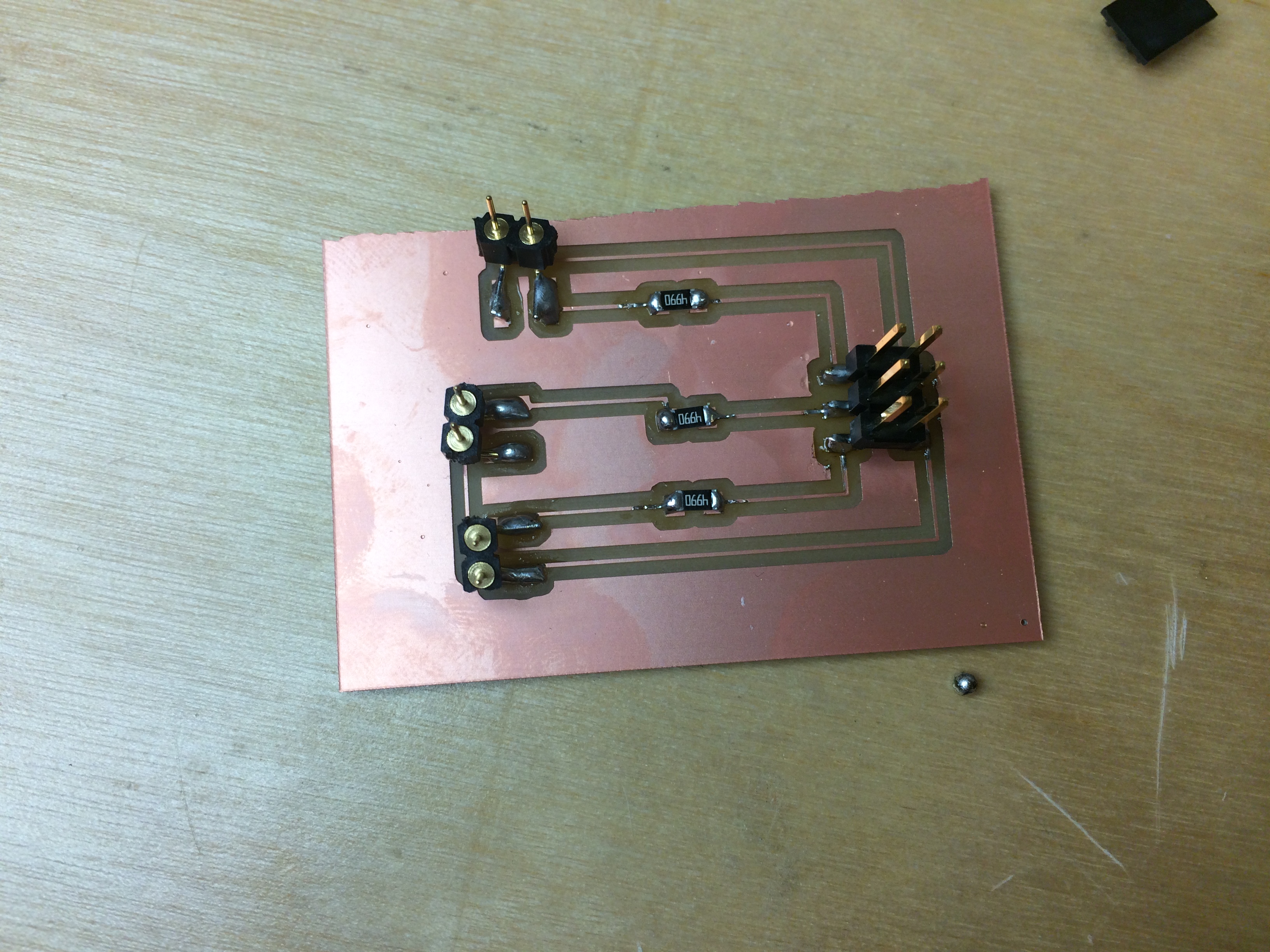
I took the board I designed in the output devices assignment and I adapted it for external LEDs. The board was simple, with resistors and pins for the LED leads.
I did not think through the grounding wires, though (I had manually soldered them together on the box itself, and I also routed them all together on the board I milled and stuffed.)
I had to make up a wire to hookup the LEDs that were already hot glued in the box, but only one of the grounding pins was actually needed.
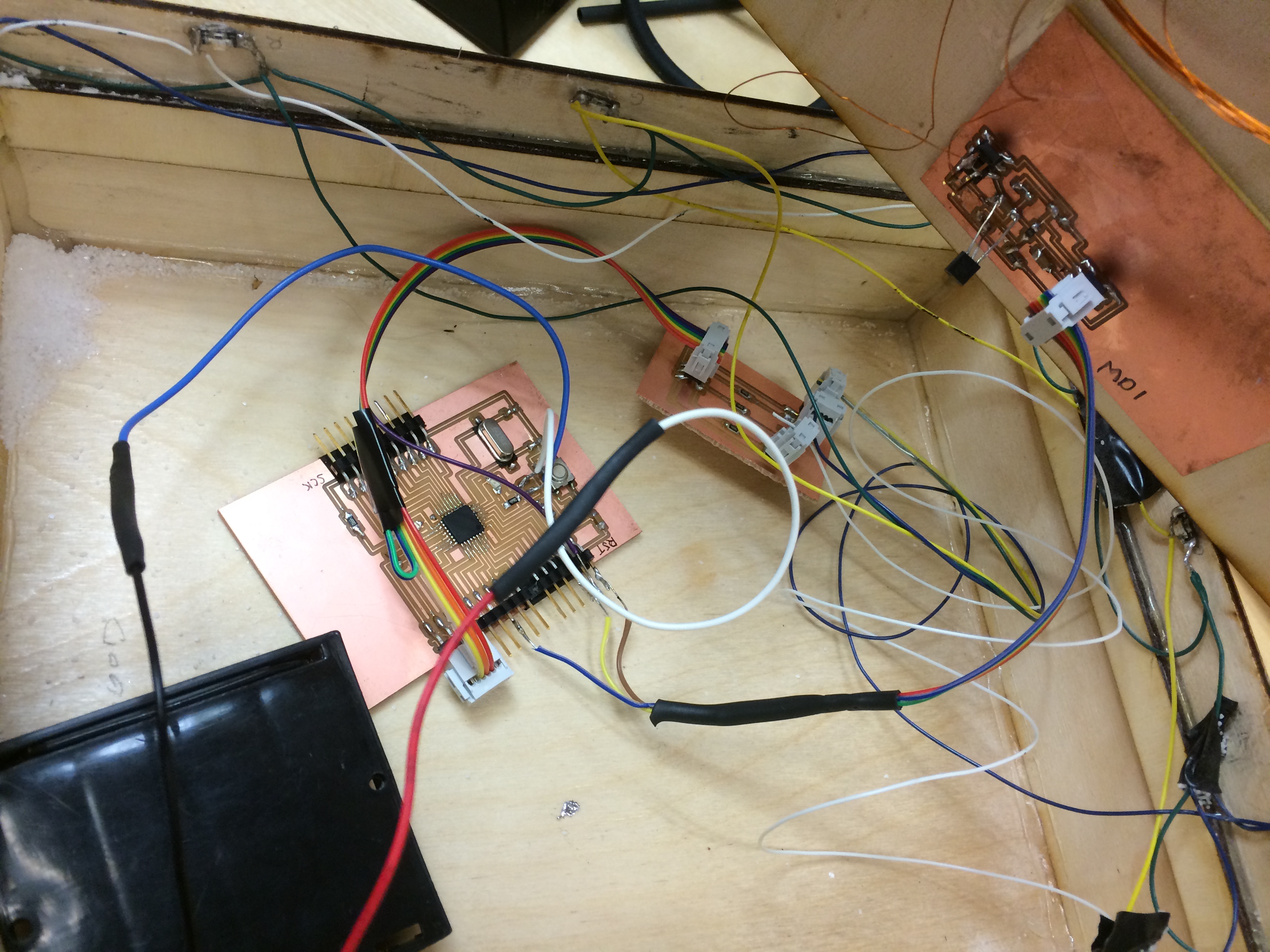
Then I made up a cable to go from the modified Satshakit board to the LED output board, which also took a little creativity. But, once everything was all hooked up, it was a lot more efficient than running with an arduino and a breadboard, which is how I tested this whole system.

Here is my final output board schematic and board.
I had a lot of trouble with my program running on the modified Satshakit board rather than the arduino, and at the moment, it isn't functioning like it did when I had four inductance coils and running on an Arduino.
With more time, I will be able to troubleshoot my programming issues, though at this point I would also like to start over on the input and instead use Hall effect sensors, which is what Neil suggested during my final project presentation. I really think I bit off more than I could chew by designing metal detector sensors in the first place. Though, I am happy that I made this journey, I learned a lot about capacitors, inductance coils, resonators, and electronics design in general, and my first iteration worked (proof of concept!).
Here is the BOM for this project. The total cost, if everything had to be ordered from the internet, would be around $55. However, since most of the materials and supplies were already here in the Fab Inventory, this only cost me about $25.
Here is the BOM xlsx file.

This code wasn't annotated very well, so I enlisted the help of James David White, who helped me understand and eventually rewrite the code. First we used four inductance coils, which we tested with an arduino and a breadboard and it worked great. Here is the code that I used for this:
4 coil inductance code
Once I changed the coil from four down to one, I actually ended up commenting out the code for three of the non-needed inductance coil circuits. I also developed a calibrating code, which was needed everytime the system was turned on. This calibration sets the baseline for the coil. The calibration code can be found here.

