
Final Project
Concept
Restating my initial proposal, I am proposing to make a smart/connected vacuum chamber, with as many of the components capable of production in a Fab Lab as possible.
The vacuum chamber fulfills two niche applications in Fab Labs. Each improve the quality of items made in the Fab Lab and one improves the sustainability of labs.
1) Vacuum chambers can be used for degassing molds. Bubbles are a common problem in molding and casting (particularly with clear compounds) and eliminating them can be quite a headache. The easiest way is to put the casting in a vacuum chamber after pouring and let it cure under vacuum. This way, the reduced air pressure forces the bubbles to grow and ultimately rise out of the cast model.
2) As Fab Labs become more self-sufficient and produce things made from locally-sourced products, labs will inevitably be interested in utilizing locally sourced wood. Unfortunately, freshly cut green wood can damage equipment and products made from green wood can fail due to shrinkage or cracking as the wood dries to match the ambient humidity. Commercially sourced wood is dried in massive kilns over the course of days or weeks. Equipment like a building-sized kiln simply is not within the scope of a Fab Lab. As an alternative, some people use vacuum chambers to dry wood. In a vacuum chamber, the boiling point for water is extremely low, so any water trapped in the wood will readily evaporate at ambient temperatures within a few hours.
Traditionally, vacuum chambers have fallen into two categories: expensive or dangerous. As the surface area of the chamber increases, the overall pressure put on the unit increases rapidly. At sea level, this pressure approaches 14.7psi/101.3KPa. A surface area of only 2 square feet/0.19 square meters would exert a force greater than the weight of a standard car! Thus, even relatively small chambers, large enough for a few small planks of wood or a few molds, must be extremely strong.
Commercially available chambers tend to be made of thick-walled metal extrusion, similar to large pressure cookers or very large diameter pipes. While fabricating the chamber from one of these components will remain an option, I would like to produce the pressure chamber from standard Fab Lab materials (such as Hydrostone/Drystone.)
Components
The overall vacuum chamber consists of several discrete components, both Fabbed and purchase. The following list indicates what the component is, if it is fabbed or not and if so what processes were used. In some cases links to relevant weeks are included.
- Pressure Vessel - Fabbed - Composites, Molding and Casting
- Pressure Lid - Fabbed - Composites Week 14 project.
- Gasket - Fabbed - Molding and Casting
- Vacuum pump - Purchased
- Vacuum sensor - Purchased
- Sensor and power control - Fabbed - electronics production, design, embedded programming
Pressure Vessel
The physical pressure vessel has several requirements. It must be large enough to fit a raw piece of wood in it, it must be airtight and it must be strong enough to withstand the (significant) pressure resulting from standard atmospheric pressure on a large surface area.
Traditional vacuum chambers are made from formed sheet metal, but this becomes cost prohibitive for significant sizes. I decided to try to overcome this issue by making a multi-layered composite and cast piece. The theoretical setup of this vessel is to have a core of high-strength plaster for compressive strength and a sheathing of epoxy-impregnated burlap for tensile strength and to absorb shocks, provide an air-tight surface and prevent cracking.
The first (and most difficult step) in this process is making a mold large enough to form this device. Specifically, the mold had to be quite large and strong both internally and externally, to allow the cast plaster to remain in place.
My strategy was to make a stack of plywood with large holes to form the outer edges of the mold and another stack of plywood discs to form the core. I made both of these stacks on the ShopBot.
To save on material (it would have taken ~8 sheets of wood to make the full mold) I decided to leave space between the sheets and line the mold surfaces with posterboard to provide a wet plaster-tight cavity.
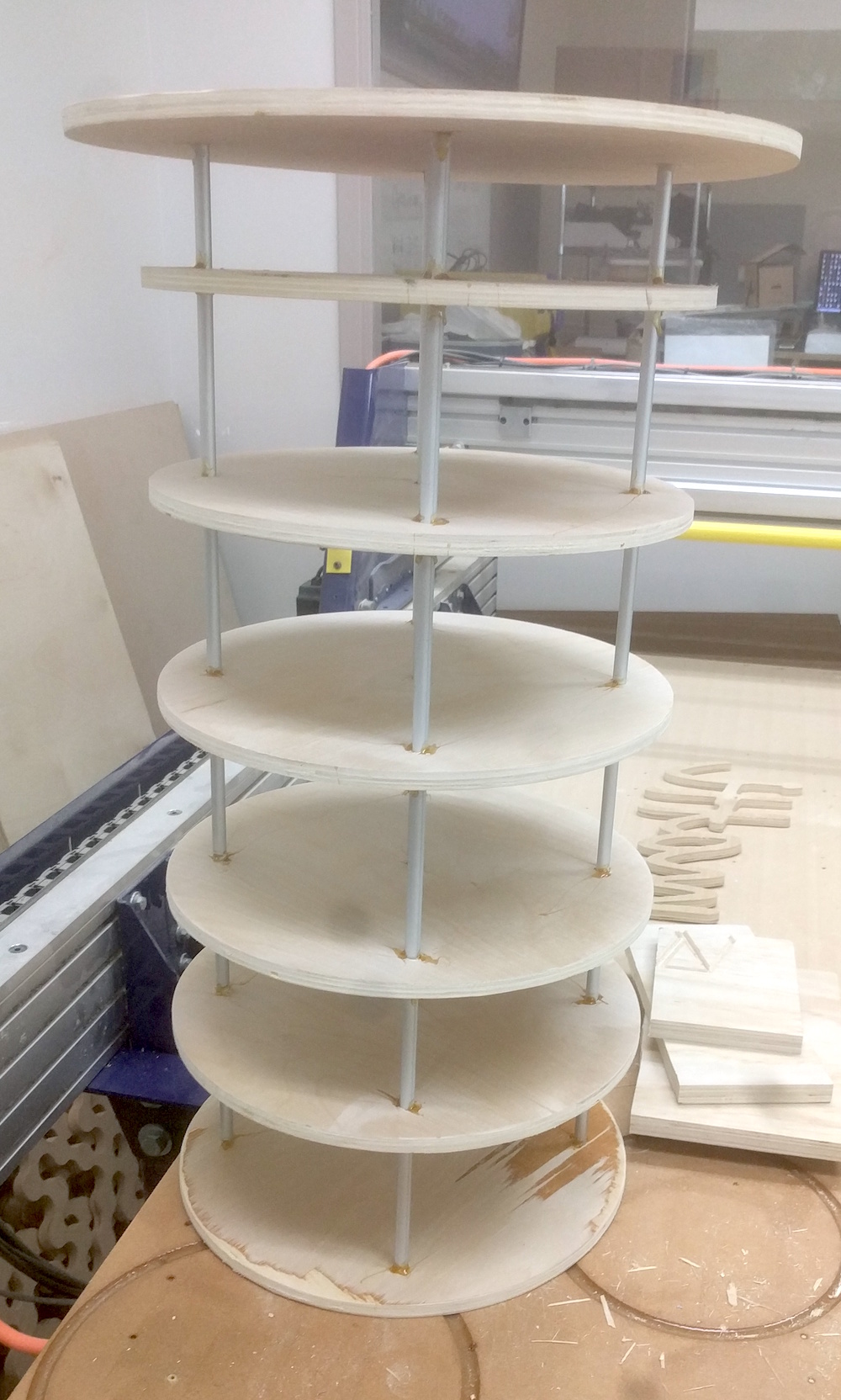
The original core
The cores with posterboard
Unfortunately, I found it impossible to smoothly layup burlap and epoxy on the interior of the outer mold. It simply was impossible to either compress the fabric or place it under tension to remove any wrinkles and squeeze out excess epoxy. If I replicated this process in the future I might use a large balloon to provide even pressure.

The significant bumps and wrinkles.
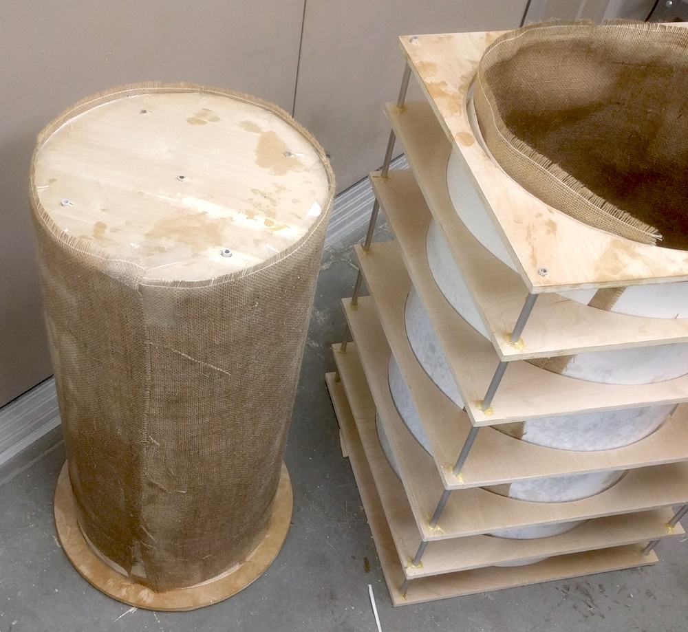
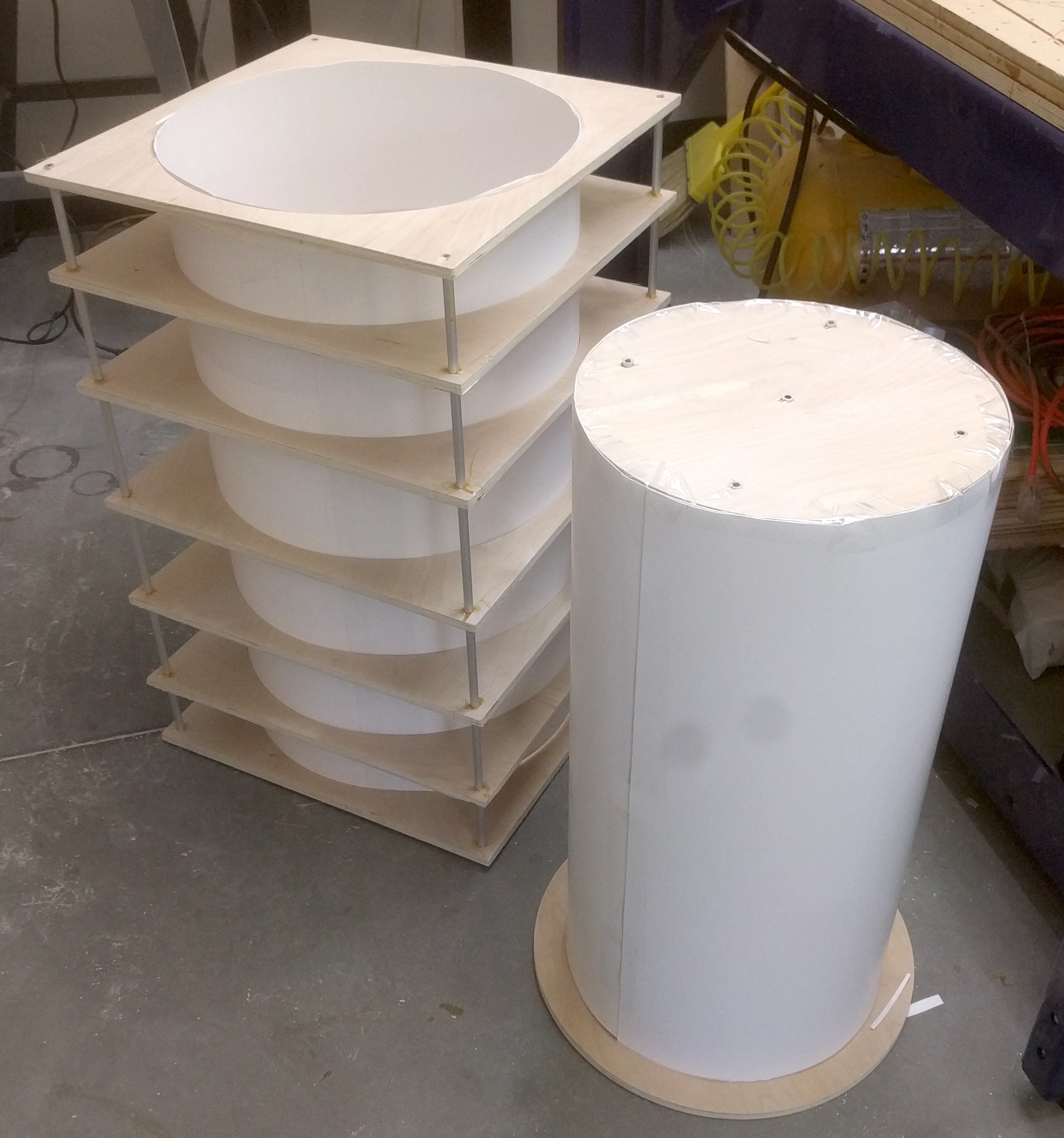
The core is much smoother, simply due to pulling the fabric around a solid surface.
The bumps and wrinkles were taller than the planned thickness of the plaster core, which is clearly unacceptable. As a result, I needed to come up with a new strategy. I decided to build the exterior in exactly the same manner as the interior and planned on removing the wooden discs before combining the sides of the mold.

This surface looks much better, plus the actual interface with the plaster will now be posterboard which should be effectively perfectly smooth (compared to burlap.)
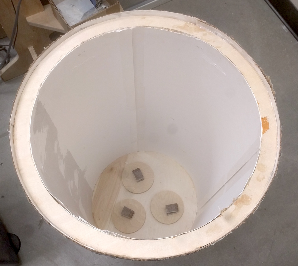
The mold needed a lip to provide a stable surface for the lid.
I embedded a few spacers in the bottom to ensure a gap between the core and the outer mold.

I then epoxied the core to the spacers in the outer mold, giving an even gap for the plaster to fill.
Pouring the plaster was a bit of an adventure. I used Drystone and mixed in some additional chopped fiberglass fibers to improve the tensile strength of the mold. My trouble arose from a combination of a few factors. The mixed plaster is quite viscous, the gap to be filled was fairly narrow and the plaster set extremely quickly. Even when I poured as quickly as possible, I ended up with some areas solidifying before I got to other areas. This was similar to freezing off sections in a metal casting, the solid areas block the open spaces.
Additionally, I was hoping for a smooth top surface from the liquid plaster finding level. Unfortunately, the solidifying process happened so quickly (it is quite warm in our lab!) that the top of the vessel ended up lumpy. This will be something I have to solve manually in the future!
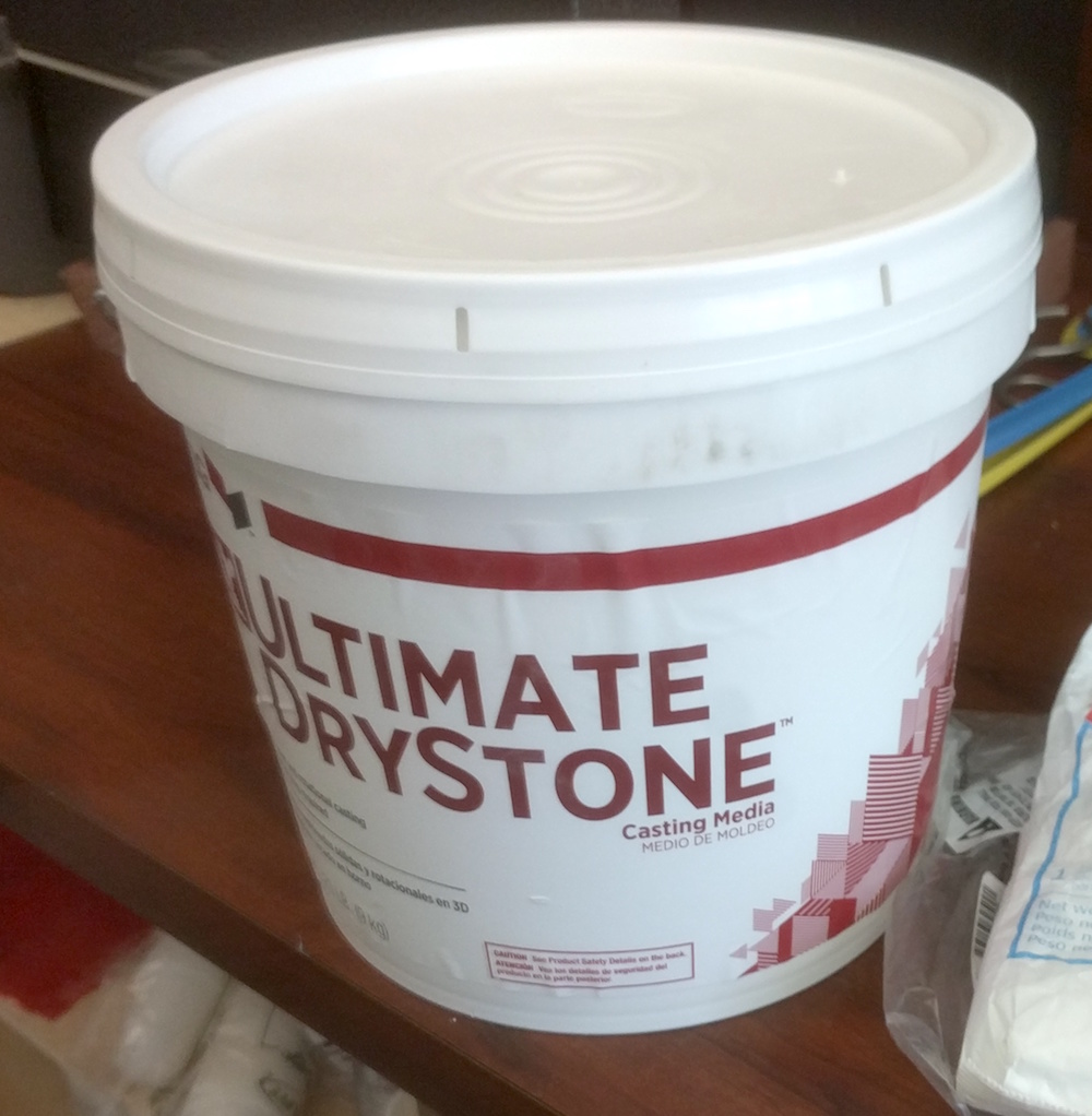
Drystone for the base

Chopped fiberglass
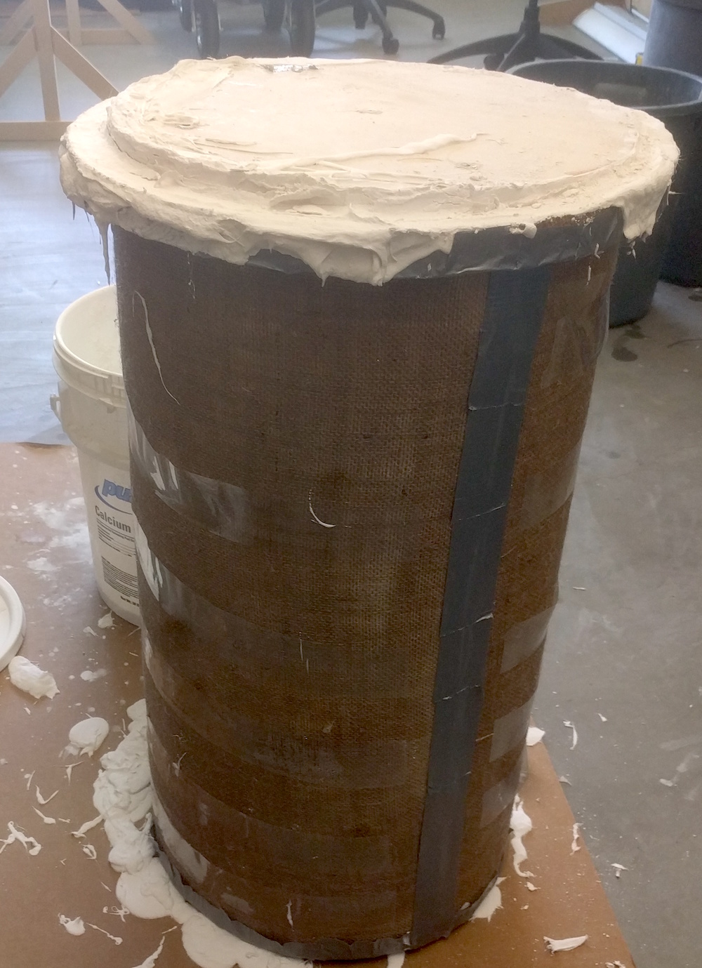
Right after the first pour
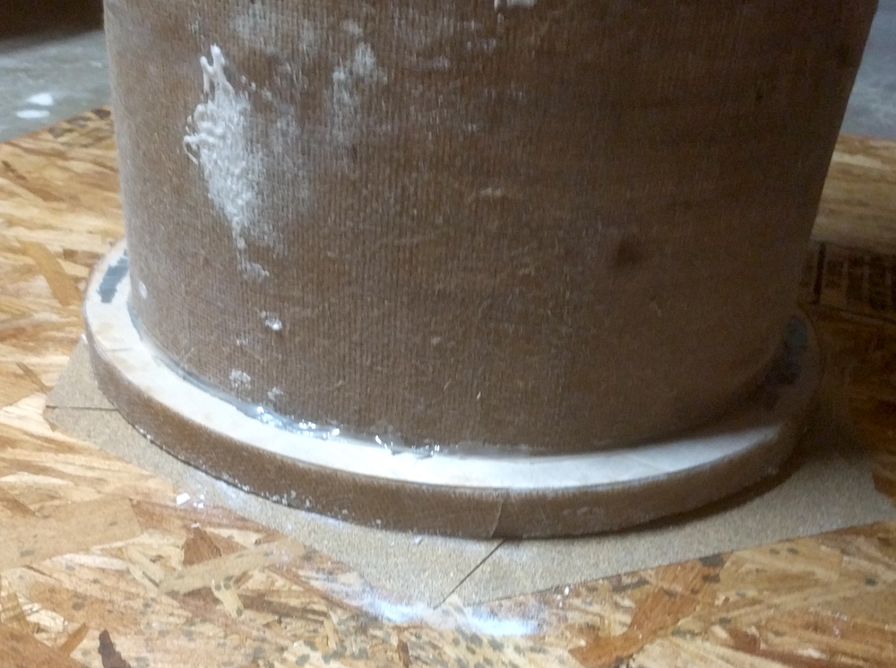
Once the plaster set, I tried to level the top surface by eye with an angle grinder and orbital sander. Unfortunately my eye is not especially good at this....
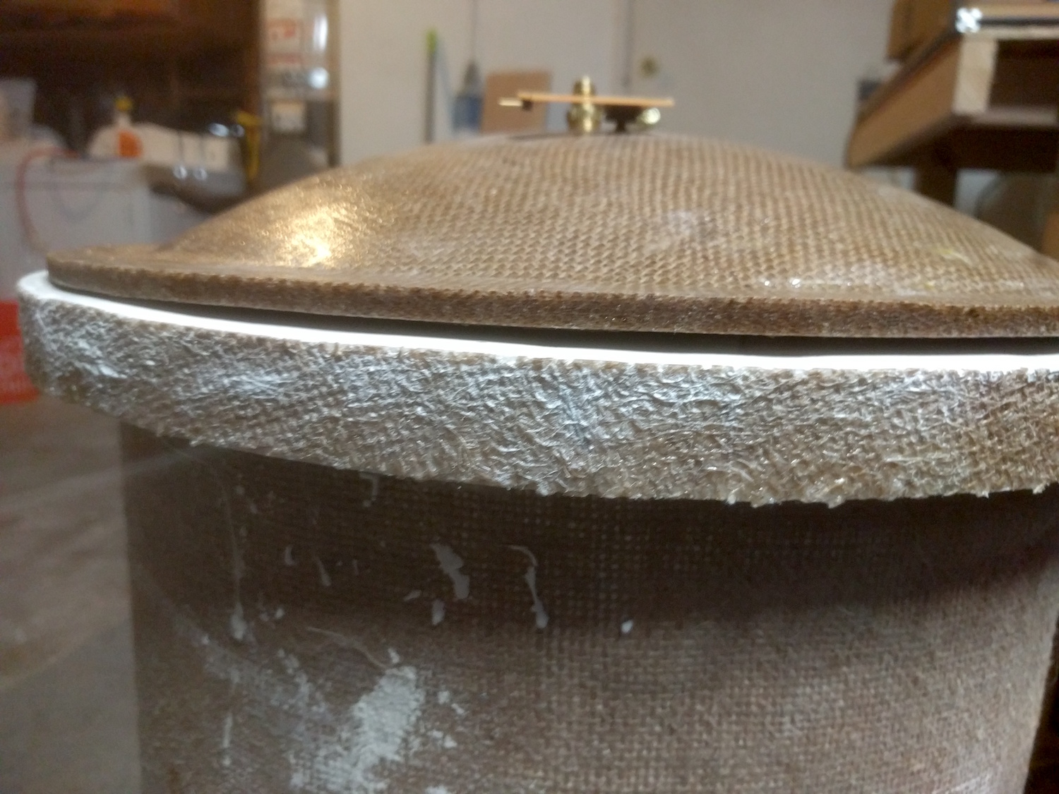
This gap is way too big for a gasket or vacuum grease to overcome.
As a solution, I thought if I used a large flat surface coated with sandpaper, I might be able to sand the top to a significantly more level state.
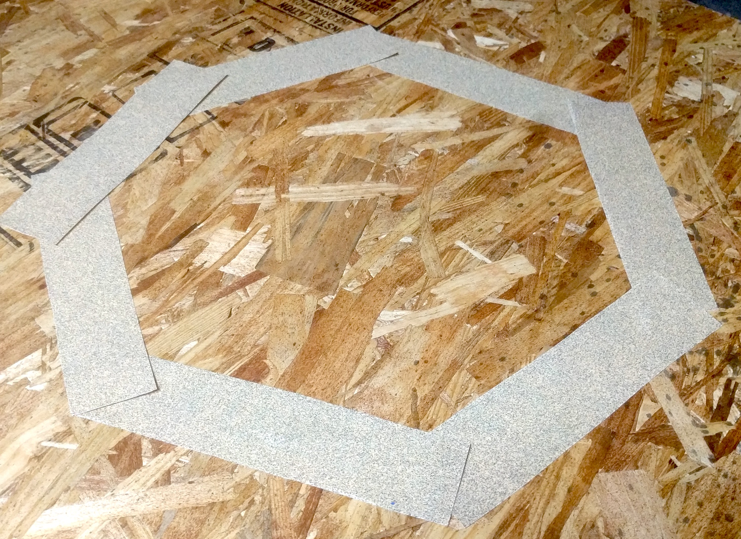
Sandpaper mounted to OSB
This actually worked!
I had previously made my gasket using silicone. This was made with a large o-ring mold milled out of acrylic on the ShopBot and then filled with Smooth-On SmoothSil 940.
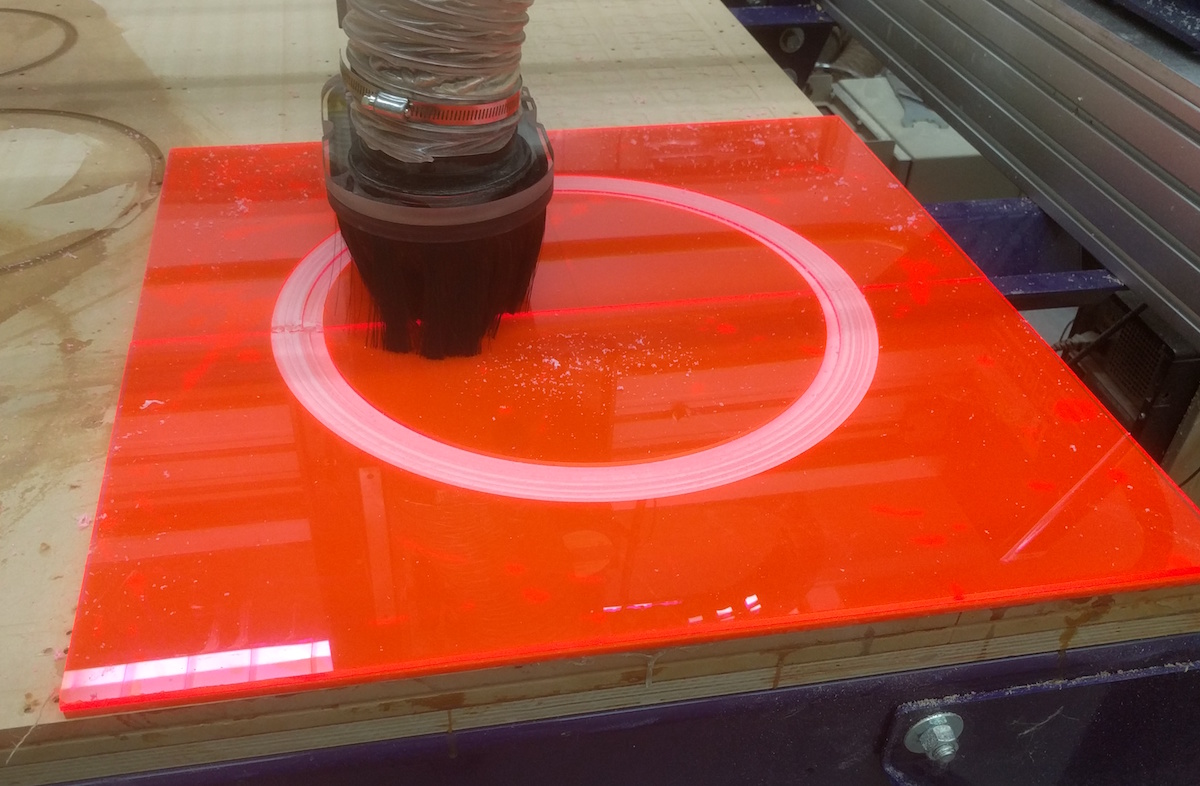
Milling out the gasket mold
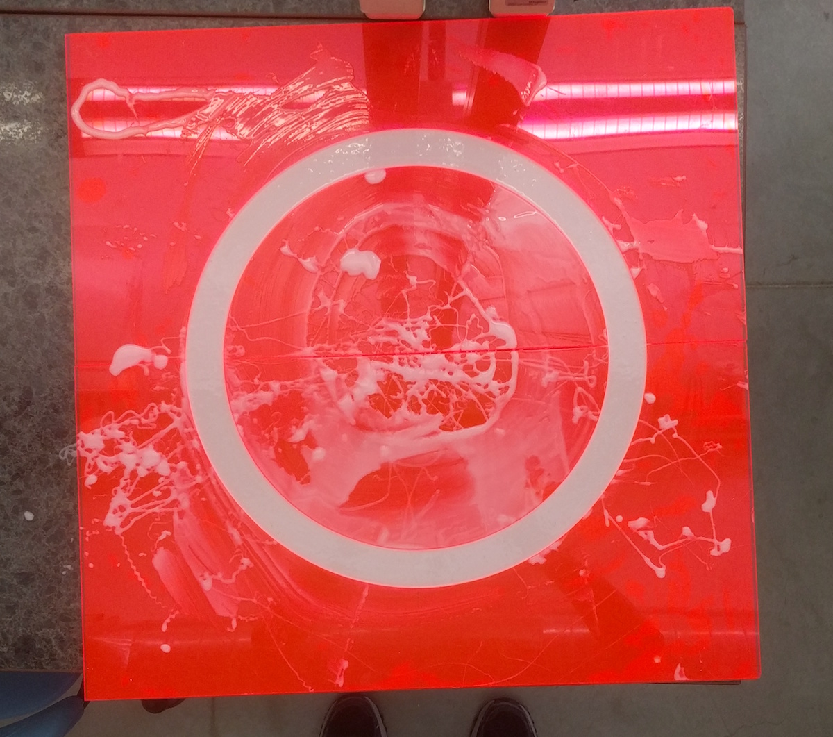
The gasket poured in the mold.
My pressure lid was constructed during the composites week. You can read about the process here.
I also added a few small holes in the top of the gasket for the vacuum connection and the pressure sensor, each sealed in place with epoxy.
With the three major components assembled, it was time to move on to the electronics
Electronics
I experimented a small amount with using Neil's example TXRX boards as air pressure sensors, but couldn't come up with a practical way to develop a housing appropriate for my application. In the interest of time, I decided to use a commercial sensor. During my presentation, Neil suggested I experiment with using a heated wire to detect vacuum, with the rate of heat loss changing relative to the air pressure. This is a great idea and is definitely something I will explore in the future.
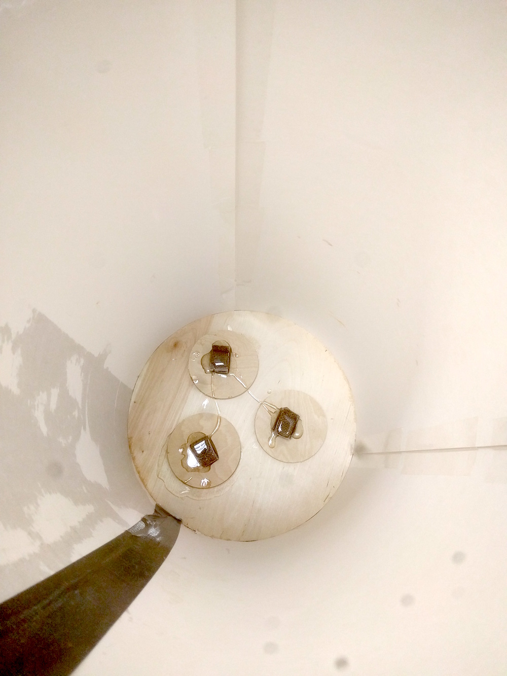
Even though I used a commercial sensor, I did modify it slightly, cutting out a small circuit board to add some standard male headers and enable removing the wires for storage or transportation. The file for this board is available here.
In keeping with the Fab Lab mantra, I did not use a commercial board for my project. Instead I made a Satshakit Fabduino to be able to easily translate Arduino code.
I embedded the pressure sensor in the lid and hooked everything up!
Results
The below video depicts the entire assembly hooked up and running. Everything looks good, but you can see a raw readout of the data coming from the sensor in the second part of the video. If this chamber was airtight, that number would be decreasing, indicating a drop in pressure. As it is, there is a massive vacuum leak somewhere in the system and tracking it down is proving quite difficult.
All in all, even though this vacuum chamber is not yet working, I am quite pleased with my progress. It is clearly on its way and I have learned a lot. With a bit more time and resources, I have no doubt I will be able to get the complete chamber functioning.
Next Steps
- Seal chamber, likely by adding multiple new layers of burlap and epoxy to the external surface.
- Add an A/C relay to the Fabduino. This will enable the pressure sensor to detect air pressure and turn on or off the vacuum pump as necessary, saving electricity and pump life.
- Dry some wood and degas some molds!