Final Project Development
MIT'S BRIEFDOWNLOAD
Lumina Smart Gadget
I discovered and learned so many things during these months. This influenced the evolving research development stages, and the way I decided to change my final project. I started to think it was the right assignment to make the correct prototype of jewelry. I was really interested in the projects of Anastasia Pistofidou who combines electronics and textiles with different processes of digital fabrication Fab Textile Workshop and I decided to change my final project because it was strictly connected with my work. So I started to think how to combine a traditional shape and an electronic board, trying to hide the circuit under a gemstone.
Jewelry is made of lights and colors and when I discovered the LED's RGB addressable strip, it totally echoed with my final project idea.Looking at 1mt of LED's strips the first idea was to make a necklace using one or more LED stripes as Sound Reactors.
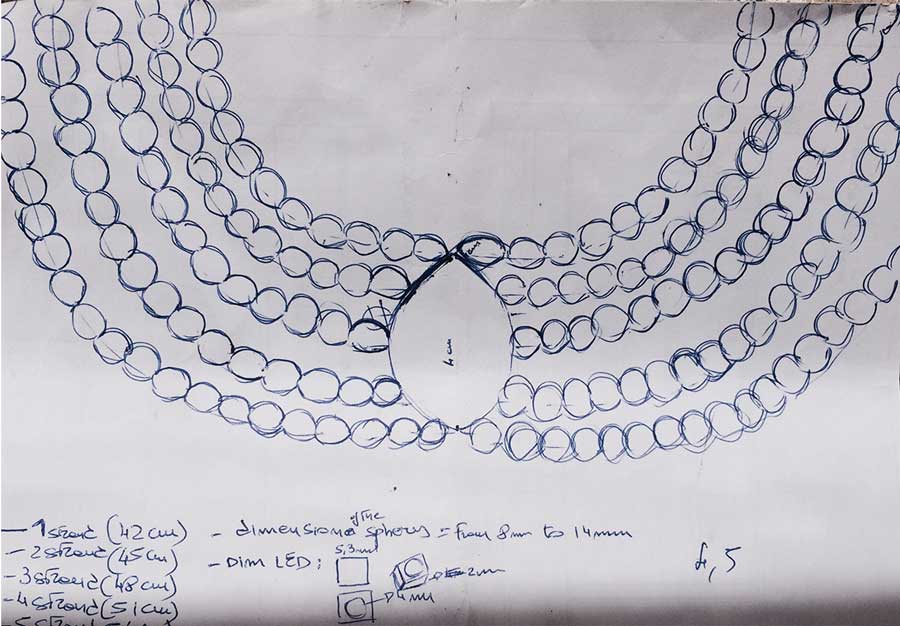
Sketch
Overview
The Lumina Smart Gadget is a sound reactive LED controller. It is supposed for application in weareable LED jewelry and light decoration. The block diagram in the image below presents an overview over the system.
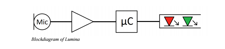
The analog frontend records the sound of the suroundings via microphone. The signal is amplified and digitized by the analog to digital converter (ADC) of the processor. The processor computes the amplitude of the sound and depending on that controles an LED stripe. Everything is powered by two coin cell batteries. This report presents the hardware, the software and an example application in a smart wearable LED necklace.
Mechanical
The dimensions of the pcb are 48mmx37mmx31mm. Battery wires are soldered directly onto the PCB.
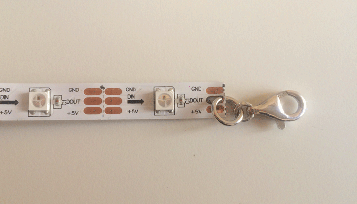
LED wires (VDD, GND, DIN) are soldered directly onto the PCB
Electronics
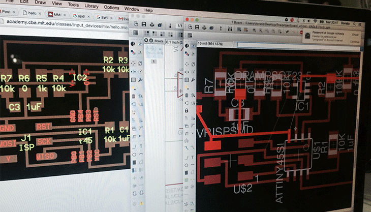
I had started by designing a board on Eagle incorporating both sound input and light output, but had first ran a test with an electret mic opamp input board based on Neil's board design, that I redesigned, milled and soldered and then connected to an Arduino Uno.
Connect and test Arduino with LED array and Electret microphone
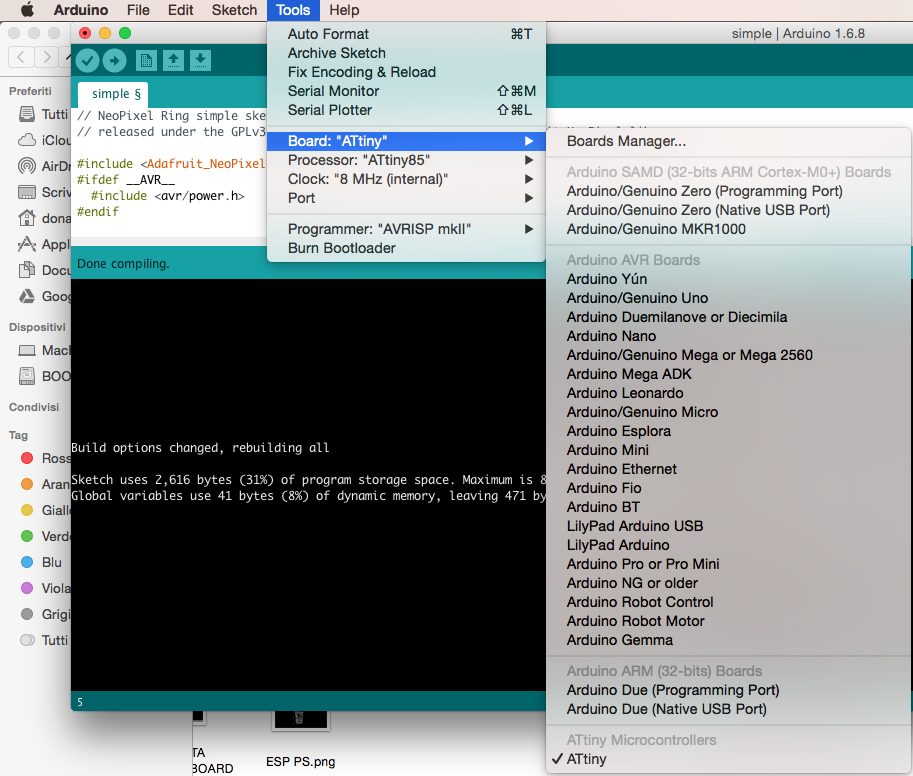
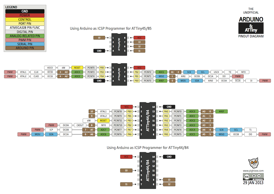
Firstly in Arduino we have to select the correct ATtiny
Open tool menu
- select tools> Board> ATtiny>ATtiny
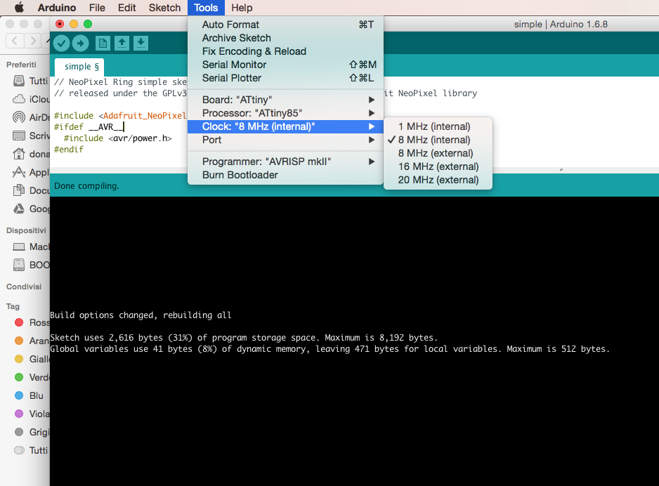
- select clock: " 8 MHz (internal)
- select Port>/dev/cu.usbserial-FT94S6V5
- processor Attiny 85


LED strip lighting - Arduino 1 + Addressable Led Strip
I used the Adafruit Neopixel Library to control the LED stripe and the arduino sketch “Strandtest.ino” to test the hardware.
Connections: - gnd>gnd
- pin6(arduino) > Din (led strip)
- 5v>5v
The Analog frontend is tested by the use of the Adafruit Electret Microphone Amplifier.
The gain of the amplifier is
adjustable.The image below shows the Test setup on a breadboard.

I tested the microphone with this code. Further information about the Microphone as Input is found in the Input Devices week.

Circuit Board Milling on Roland monoFab SRM-20
I milled several times the board because the dimension of the pendant was too big and after 4 tests I got a valid size(48mmx37mmx31mm)

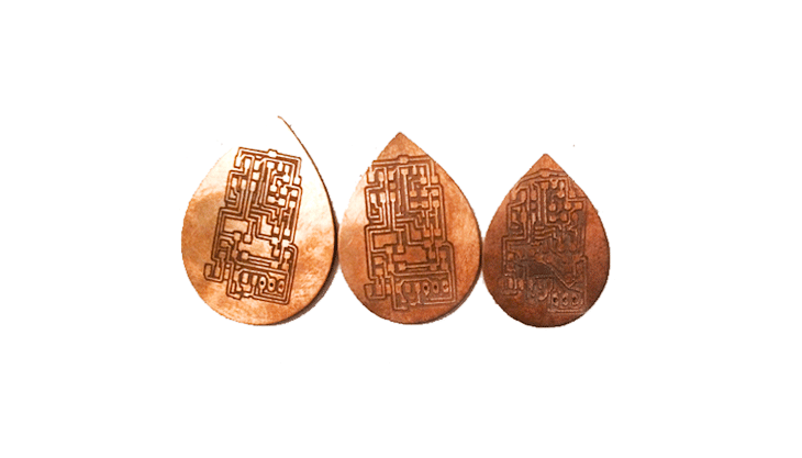
For this purpose, I redesigned it again to suit the needs and milled again with Roland srm-20.


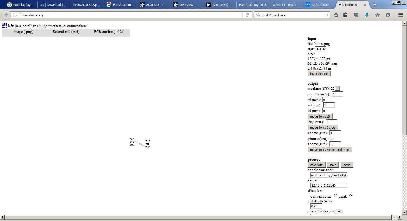
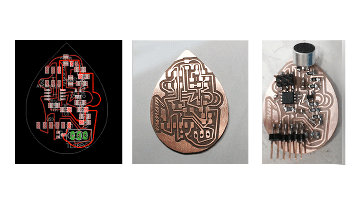
Trace,Outline and Holes
.gif)
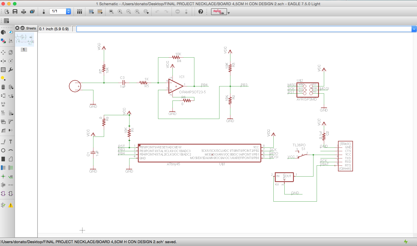
Schematic
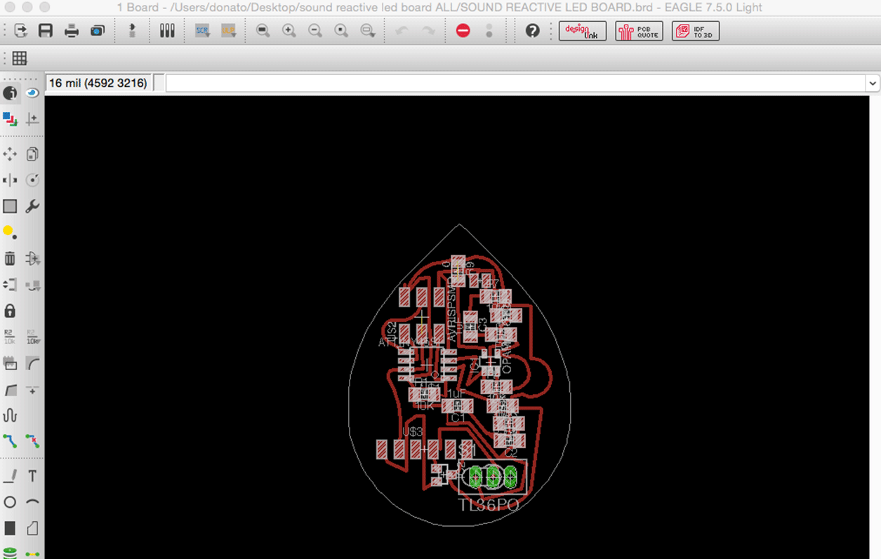
Board
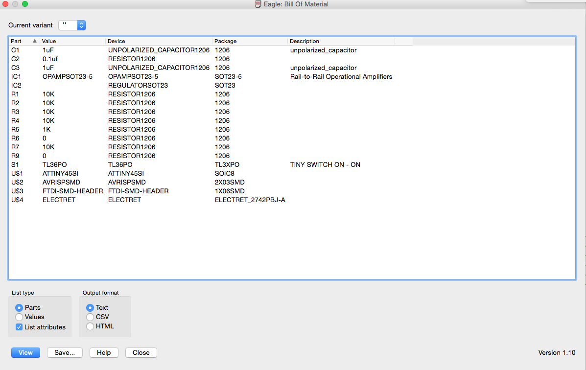
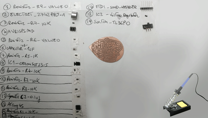
Electronic components
and
Soldering

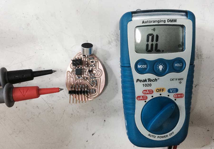
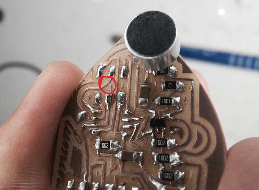
After manufacturing the pcb, the first test showed that the audiosignal stayed constant at 0V. This error was created by a short circuit between the audio signal and ground. The image below shows a picture of the critical section. Because both nets are close to each other, it is recomended to check the isolation between those nodes before the circuit is operated.Make sure to check the traces of the circuit prior soldering the components.For this small connection my board did not work for a while.
These two useful tools helped to remove the components as well as the solder

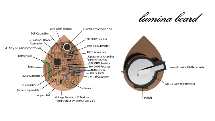
The "Lumina board"
Battery
I used one coin cell battery holder( 2-20mm cells) and 2X Duracell 2032 Coin Cell Batteries.
Battery wires are soldered directly onto the PCB.
LED wires (VDD, GND, DIN) are soldered directly onto the PCB


Programming the board
To program the board, I used first the code strandtest.ino based on the ADAFRUIT NEOPIXEL LIBRARY and then I have tested also the Arduino code called LED COLOR ORGAN which I needed for my Arduino UNO in order to make the circuit recognize the sound and blink through a LED strip.
Before loading the strandtest and the Led color organ codes, I needed to install the Adafruit Neopixel Library downloadable here
Installation of the library:
Visit the Adafruit_NeoPixel library page at Github.com.
Select the “Download ZIP” button, or simply click this link to download directly.
Uncompress the ZIP file after it’s finished downloading.
The resulting folder should contain the files “Adafruit_NeoPixel.cpp”, “Adafruit_NeoPixel.h” and an “examples” sub-folder. Sometimes in Windows you will get an intermediate-level folder and need to move things around.
Rename the folder (containing the .cpp and .h files) to “Adafruit_NeoPixel” (with the underscore and everything), and place it alongside your other Arduino libraries, typically in your (home folder)/Documents/Arduino/Libraries folder. Libraries should not be installed alongside the Arduino application itself.
Re-start the Arduino IDE if it is currently running.
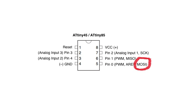
Once I downloaded the Library I had to define the correspondent digital pins of my microphone and the ones of my LED strip for the Microcontroller of my board - replacing the correspondent value in Arduino.
To program the board, firstly I connected the board to the fabISP and to the computer using the FTDI cable and the usb cable to provide power.
Result:
MIC pin:A1
LED pin:0


First test with the digital RGB LED Strip
Sensitivity of the microphone
The basic idea was that the microphone , soldered to my board, reacted listening to the ambient sound and picked up sounds that cross a certain decibel level. Here, the sound I captured was really low and Guillheme suggested that I tested the 10k resistor connecting it into an Oscilloscope in order to verify the intensity of the sound.
We discovered that the reaction we obtained was really low even if my necklace changed color as planned by my initial idea. So basically I had to change the resistor and decrease the value of the gain in Arduino.

Bumping on the microphone is much louder than for example talking. I guess as explained before the gain of the amplifier is simply too low. It should be enough to choose new resistor values.
Strandtest
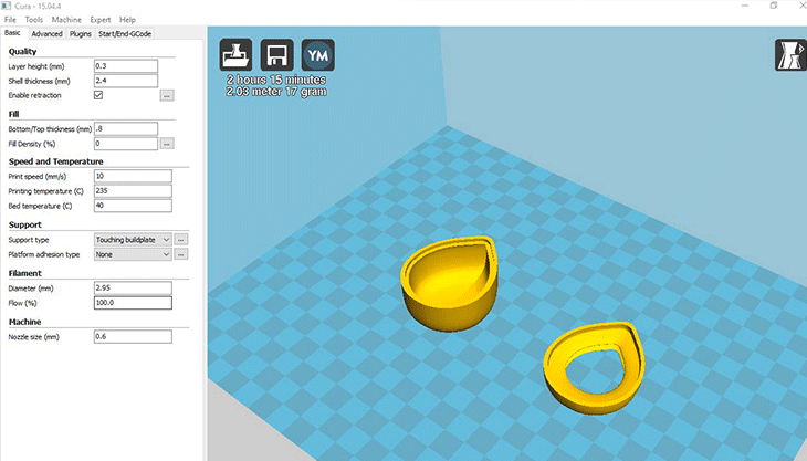
3D Print
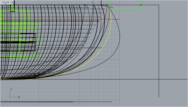
With the program Rhinoceros I modified several times the shape and the section of the box pendant which contains the circuit, the battery, and a switch in order to get a tiny shape and I used the command rail Revolve to create the surface.
The problem was the dimension of the battery and the thickness of the final box.
First 3D Print
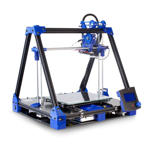
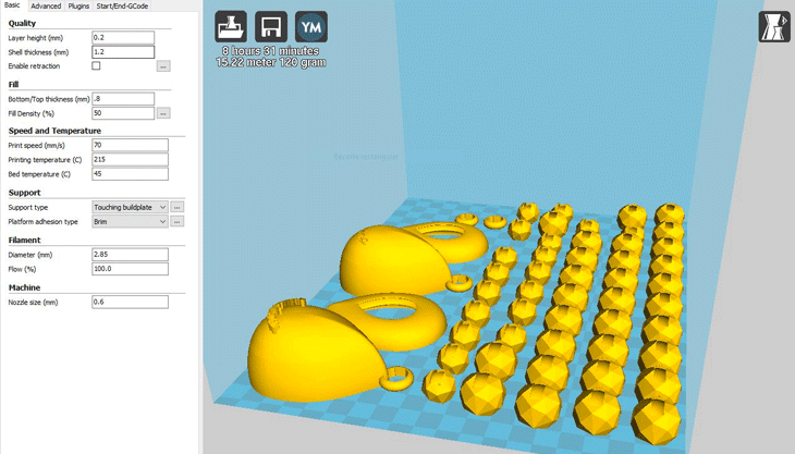
I used the BCN3D+ to 3D print the elements of the Necklace using first blue and white PLA filaments as first prototypes and then I used the transparent filaflex to 3D print all parts which allowed light to pass through the material.
Cura settings
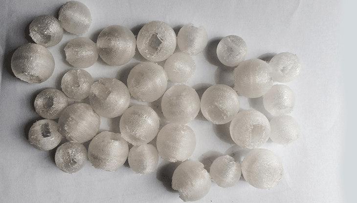
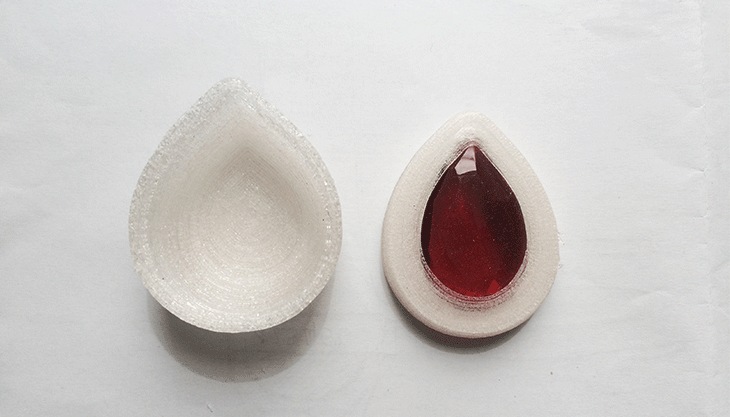
Spheres
I also modified several times the thickness and largeness of the spheres but at the end I got a good dimension and I also liked the material ( filaflex) I used to print them

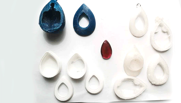
After several tries and after many prints I got a good shape with a reasonable dimension of the drop box.

Final Project Presentation
Finish the Final Project and present it to Neil Gershenfeld and the Fab Academy community.

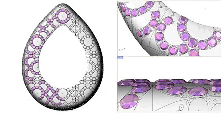
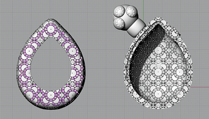
After the presentation I decided to focus on the design of my Final Project and I redesigned the spheres, the drop box and the connectors in order to decorate the Necklace. I was inspired by Barcelona's tiles and in particular by El Panot de Flor, designed by the Catalan architect Josep Puig i Cadafalch, one of the urban symbols around the city of Barcelona.

Closing System
I also found and redesigned a different clasp in Sterling Silver 925/000 for the necklace to change the lobster clasp which I used for my first prototype.
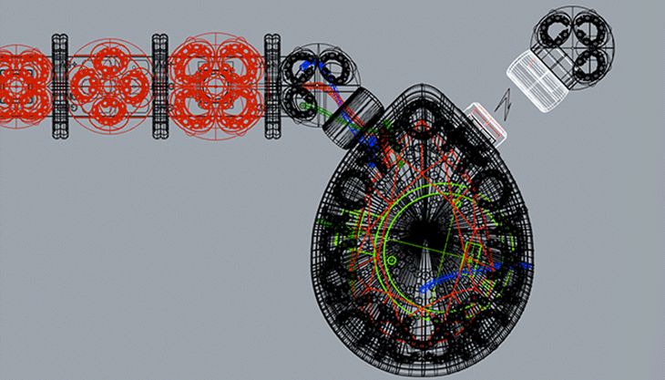

Connectors

3D VIEW
What is the deadline? How much time do I have left?
I worked 3 weeks for my final project and it was absolutely not enough time to finish the project as I wanted ( electronics,design,3d printing) anyway it was just a protoype and a useful test of my initial idea.
What tasks have been completed, and what tasks remain?
Task Completed: Electronic Circuit and Electronic Design
Programming with Arduino using Adafruit_NeoPixel->strandtest sketch and Led Color Organ sketch
Dimension of the box(pendant):Highness(48mm) and largeness(37mm)
Verified stability of the hydrothermal gemstone into the 3d printed box(pendant)
3D printed elements of the Necklace
Task remain:
Using a Lipo battery
Picking up sound properly adjusting the gain
Modify the thickness(31mm) of the box(pendant).It depends on the new battery
Design a customized and parametric 3D model
Increase the operating time of the Necklace
How will I complete the remaining tasks in time?
My plan was to have the electronic part working and it worked during the presentation to Neil and to my peers.I will improve the design part once I can make the electronic parts even smaller.What has worked? what hasn't?
The Final Project was just a prototype and I'm happy with it.The machine worked but I needed to understand which battery I could use for a product.Worked:
-The Lumina board
-Stability of the hydrothermal gemstone into the 3d printed box(pendant).
Not worked:
As I said in the remaining Tasks:
Picking up the sound environment properly and programming specific light patterns.
The closing system of the box(pendant).I just used glue to close the 2 parts together.
What questions need to be resolved? What will happen and when?
I redesigned the necklace and I'm working on the closing system of the box but I'm going to resolve the biggest problem..the battery! I hope to get my final product in October 2017.
What have you learned?
- New Design Software(Brackets, Eagle, Blender, Remake, Inkscape and many others)
- Coding and Electronics
- I learned how to use new machines and make my own machine.
My goal at Fab Academy was to improve my general knowledge of Scanning, my passion, and to get a prototype of a jewelry piece but doing that I discovered 1000 new things..like new tools or new open source programs ( now I love Meshmixer and Blender) and after a long work of designing and research I got my first prototype.
The biggest problem was how to get the smallest 3D printed drop for a pendant but combining these parts with electronics that I started from ZERO.
I started with a circuit board of 70mm in highness, huge for a jewelry pendant, at the end I got a drop shape of 48mmx37mmx31mm.It's a result!I'm quite happy with it.The thickness of the box was before and it's nowadays a problem.The goal could be fit two Lipo batteries of 3.7V 500 mAh into the drops and connect them together.The size of one battery is 21mmx19mmx2mm or just using one single LiPo battery of 48mmx30mmx9mm that I found in the Market, that could be an idea to increase the operating time for the Necklace.
DOWNLOAD FILES

This work is licensed under a Creative Commons Attribution-NonCommercial-ShareAlike 4.0 International License.