Fab Lab Barcelona 16 Team
"Just a minute, Please Don't move"- Donato Polignone
Test the design rules for your printer
Design and 3D print an object
3D scan an object
The assignment for this week was to scan and print an object and improve our abilities in this field.
A 3D scanner is a device that analyses a real-world object or environment to collect data regarding its shape and possibly its appearance. The collected data can then be used to construct digital three-dimensional models.
In our Lab, we used two different types of 3D scanners, non-contact and contact.
3D Laser Scanning is a non-contact technology that digitally captures the shape of physical objects using a line of laser light. 3D laser scanners create "point clouds" of data from the surface of an object.
Contact 3D scanners probe the subject through physical touch, while the object is in contact with or resting on a precision flat surface plate, ground and polished to a specific maximum of surface roughness.
In our Lab we used the Microsoft Kinect combined with the software Skanect as non-contact laser Scanner and ROLAND MDX-20/15 , combined with Dr. PICZA software, as contact 3D Scanner.
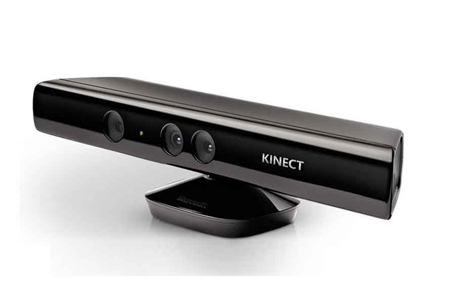
Microsoft Kinect is an affordable 3D scanner which uses infrared laser light with a speckle pattern.
Basically, The Kinect uses an infrared projector and sensor to scan objects.The technique of analyzing a known pattern is called structured light. This 3D Scanner combines structured light with two classic computer vision techniques: depth from focus, and depth from stereo.
With this 3D scanner, it is possible to get 3D meshes out of real scenes in a few minutes.
Advantages and limitations of this Scanner: it is able to scan big models fast but it's not as precise as other high-end scanners, such as The Roland MDX- 20/15,
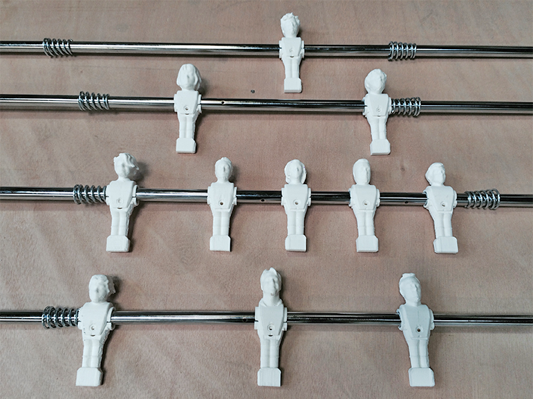
I used this 3D Scanner in order to transform my collegues into players and to get at least eleven 3D models for the "Footballino"(football table) created by my colleague Elia De Tomasi.
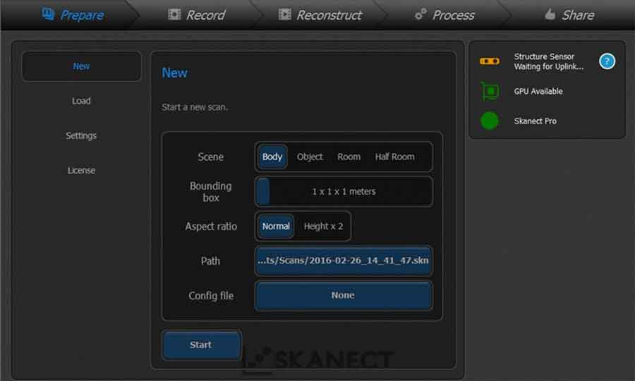
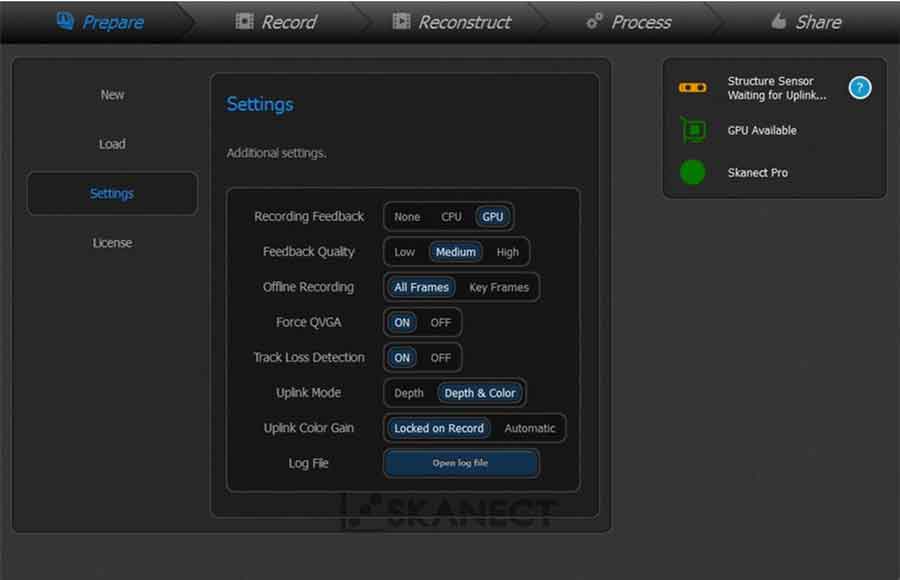
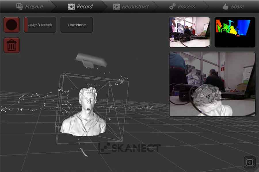
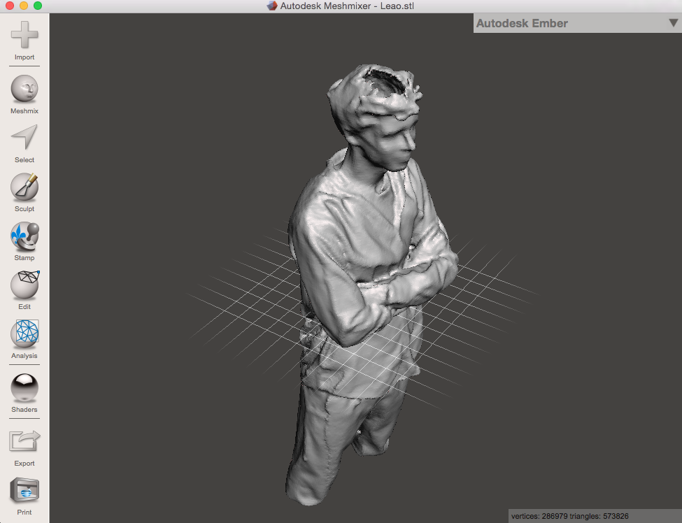
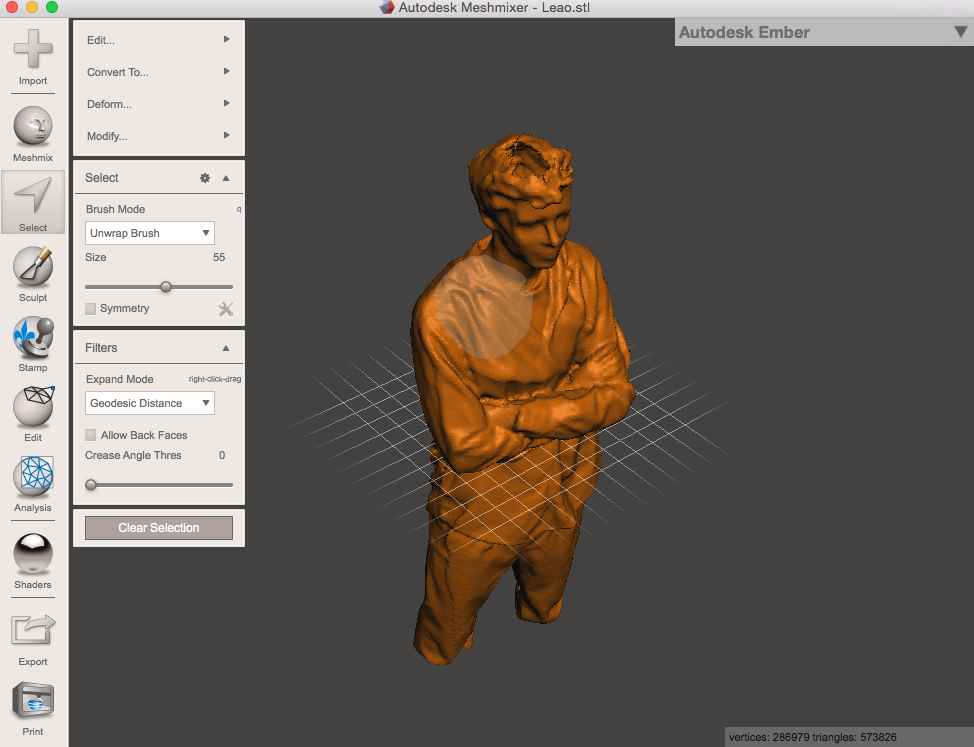
The images below show one of my colleagues Joao Leao during his Scan and the basic settings I used in Skanect to:
- Set the virtual box with the software Skanect in order to specify the size of the model
- Set the additional settings
- Record part of the body
- Export the 3D model
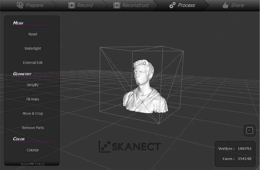
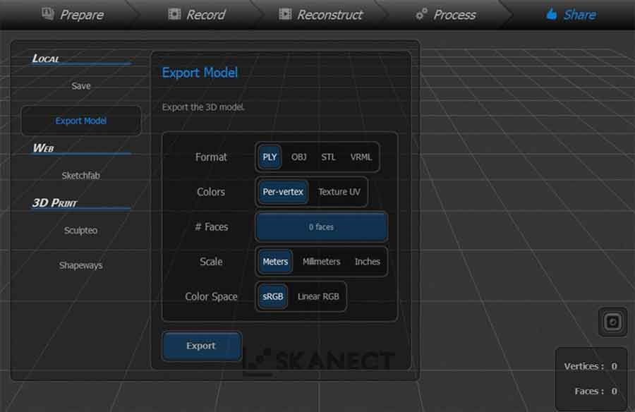
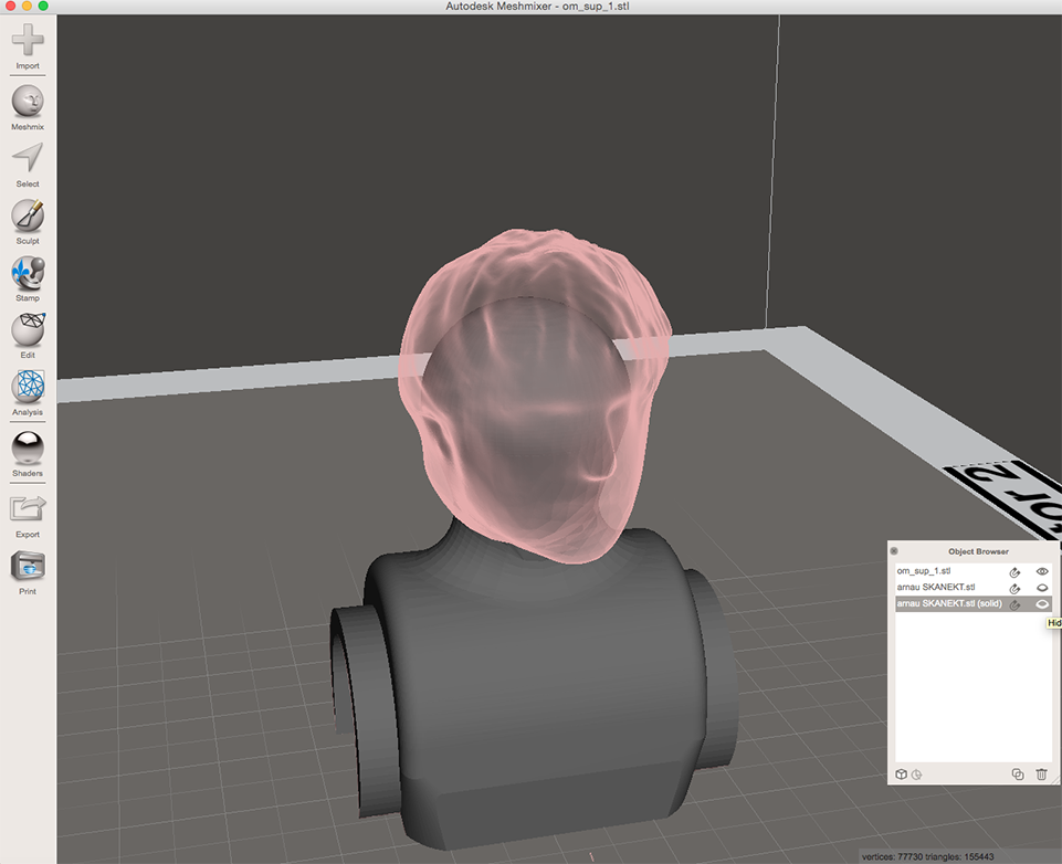
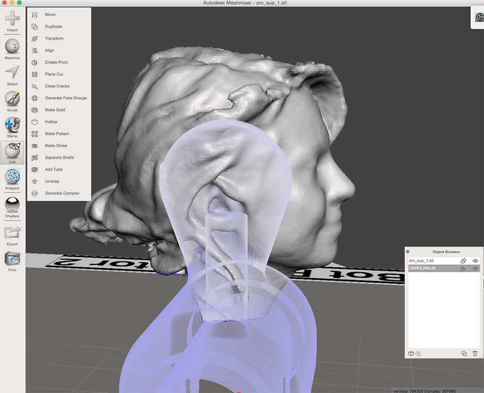
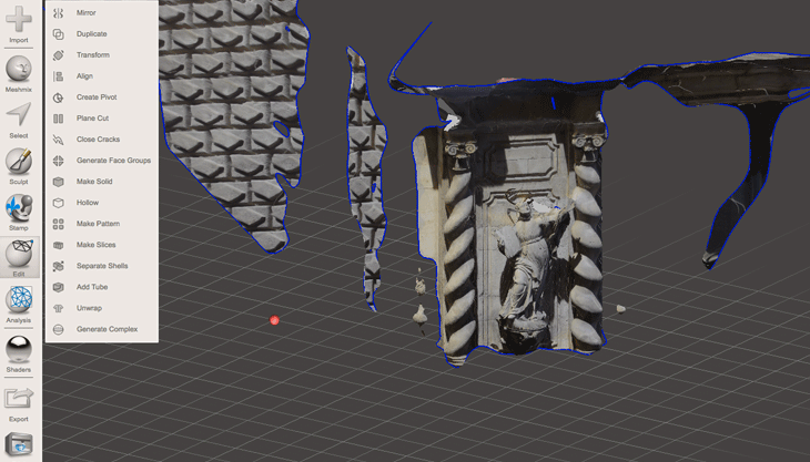
Once I got a .stl file (I could also export the file in .PLY .OBJ or .VRML) I imported the 3D model in "Autodesk Meshmixer" to clean up the given mesh and combine two 3D models .
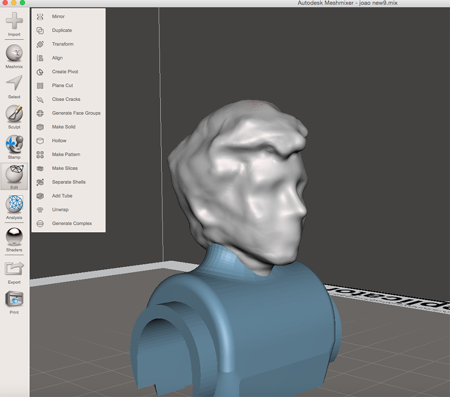
To do that, I just downloaded a standard player from Thingiverse and replaced the face of the player with the faces of my colleagues just joining them with a boolean operation.
Firstly I imported the scan data using the command File > import
Some common tools I used in Meshmixer:
- Edit> Transform to reposition data
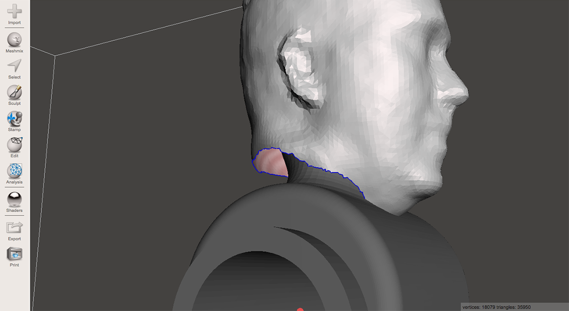
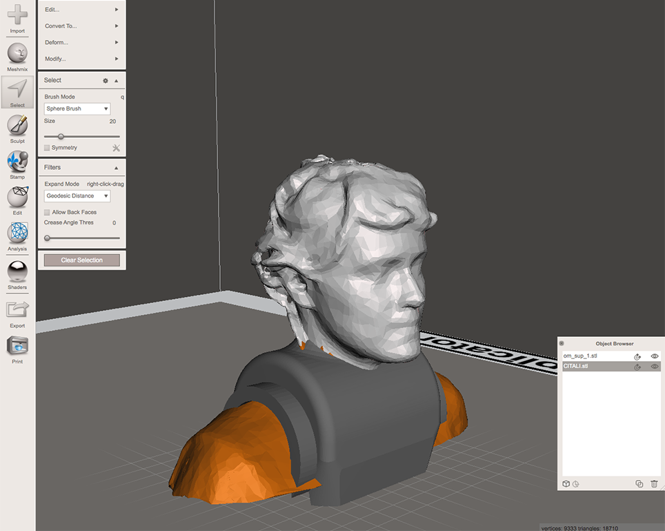
- Select tool > lasso or brush to delete some extra points caught up during the Scan. Use a brush or a lasso to select just a small area, double click to select all or "I" on keyboard to invert and delete key to remove
Another method to fix problems of the given mesh is to use the Inspector, click
I repeated the same process to obtain 11 players.
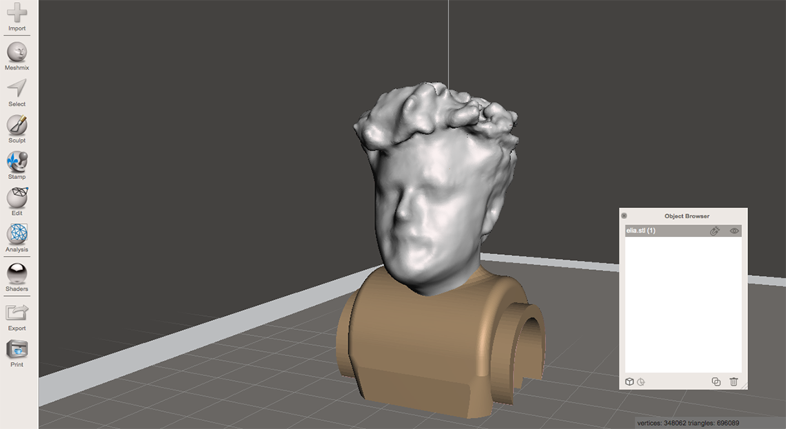
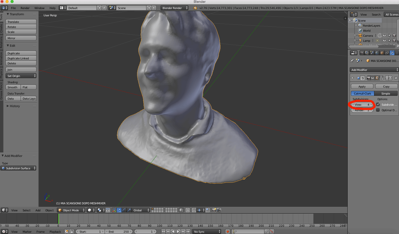
I also used Blender to modify my personal mesh using the useful tool subdivision surface.According to Blender's Manual This tool is a method of subdividing the mesh faces to give a smooth appearance, to enable modeling of complex smooth surfaces with simple,low-vertex meshes. This provides high resolution of the 3D model and gives the model a smooth and organic look.
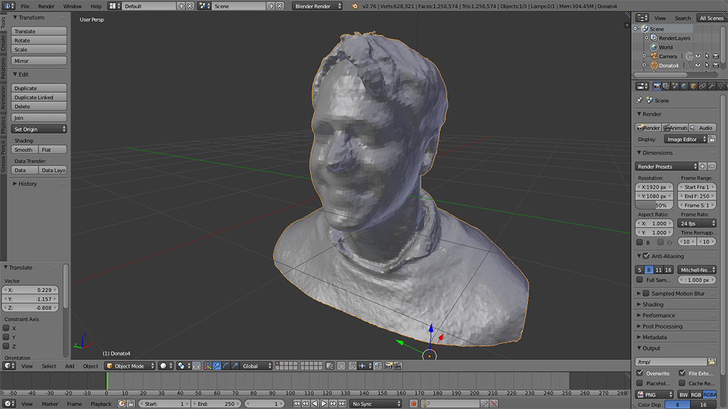
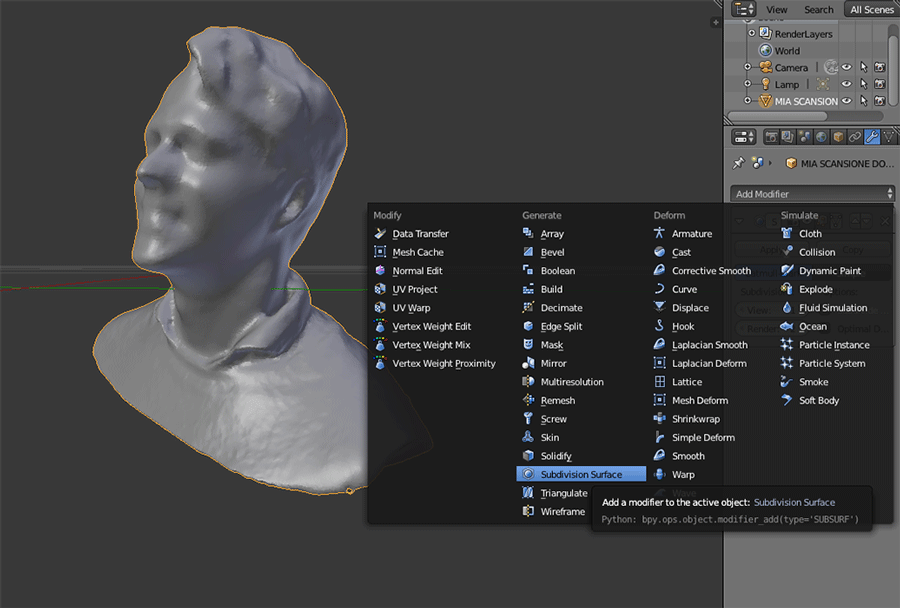
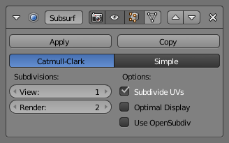
*Higher levels of subdivisions result in more vertices, and more vertices result in more memory used. Blender could potentially crash or hang if you do not have enough memory. I used 4 steps of subdivision ( view 4) and Blender ran very slowly.
*Be careful not to set the View subdivisions higher than the Render subdivisions, this would mean the 3D View will be of higher quality than the render.
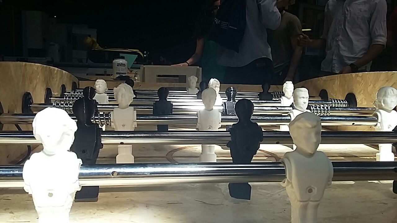
Our 3D printed models at Fira Barcelona for the event IN(3D)ustry
Our 3D printed models at Fira Barcelona for the event IN(3D)ustry
All 3D scanners have issues in catching shiny, mirroring,reflective or transparent objects.General issue of scanning are related to the Mesh refinement.
The Roland Modela Mdx-20 is a desktop 3d scanning and milling machine that is compatible with many popular 3D CAD software.The software to be used with this machine is the Dr.PICZA software.
This contact 3D scanner allows scanning small objects thanks to the
Roland Active Piezo Sensor, which is able to scan small objects at 4 to 15 mm per second with a resolution of up to 0.05 mm.
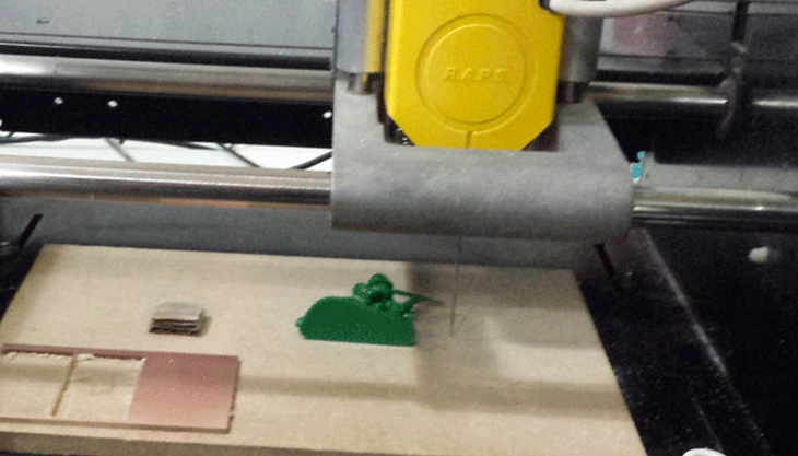
For this group project we scanned a little soldier using the Roland Modela.
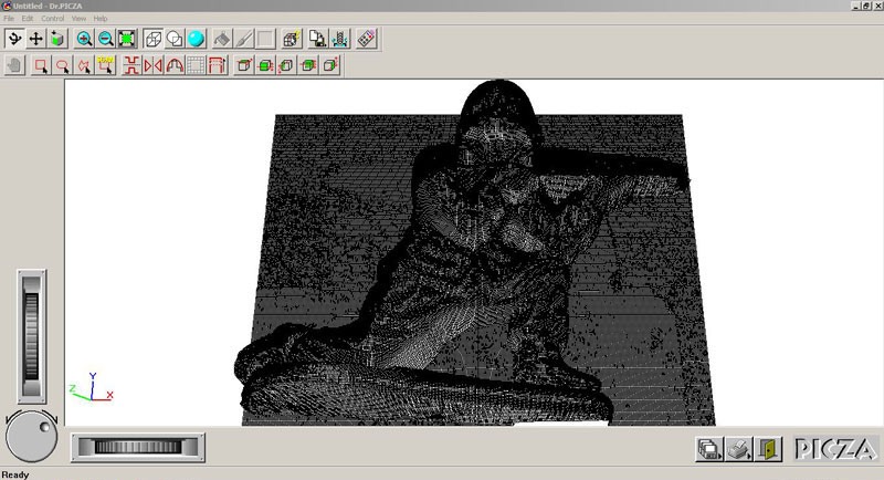
It took 18hours to get the final .stl file, 9 hours each side, at the end the result of the scan was precise with a very good resolution of each part.
SET UP Roland Modela+Dr.Picza
-Open Dr.Pizca program
-Set up the piece to be scanned in the machine with double sided tape
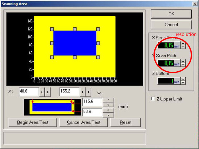
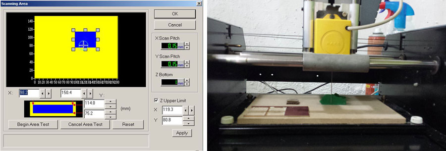
-Set up the area to scan
-Set up the Z upper limit
-Save the .stl file
The day after we repeated the process for the buttom side of the soldier and joined the parts
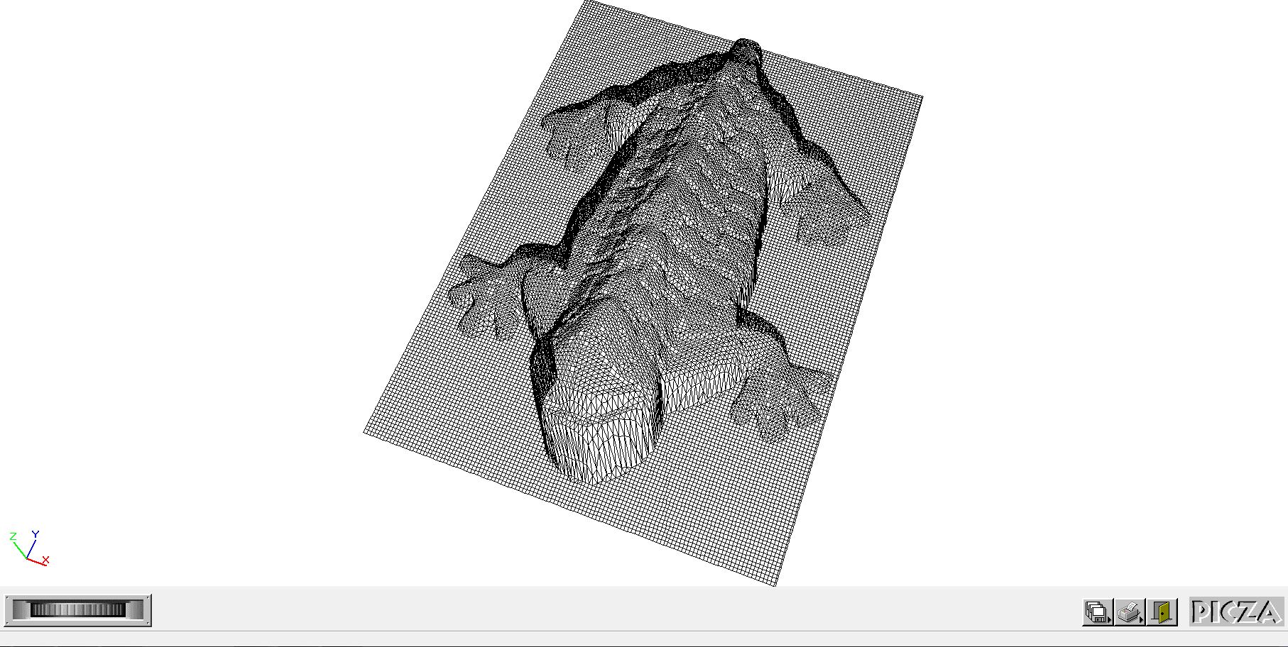
For this second test I wanted to scan the details of the shell of a 3D printed turtle and I repeated the process:
- Set the area of the base that we want to scan (We can adjust the blue rectangle surrounding our object by dragging the arrow that appears on the perimeter of the rectangle.)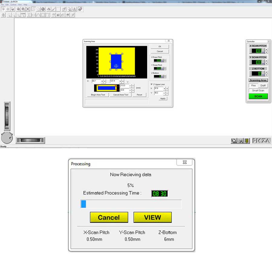
Once the scan is finished we will obtain the first mesh and we will export in .stl .
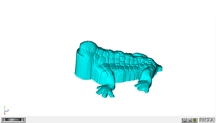
Advantages:It's a precise scanner for small objects and It can even scan glass, impossible using optical scanners because the light beams passes through the object without detecting it and it can also scan soft objects.
Limitations:it can not scan big models and it's slow .
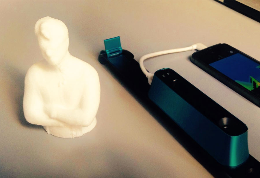
The Structure Sensor can work with my iPad or iPhone via the free application 'Scanner'.The scan (.obj) will be compromised and now it's ready for getting processed. The Structure Sensor can also work with the iPad or iPhone and a laptop (recommended) via the application 'Skanect' running on the laptop and the free application 'Structure' running on the Ipad (mode Uplink: the laptop and the Ipad are connected via an ad-hoc wireless connection). From 'Skanect' you can export your 3D scan in .ply, .obj, etc, but not .fbx straight. The sensor can also work without an Ipad, via USB connection to a laptop/desk computer running 'Skanect'. Please note in this case you do not get the color information (the sensor uses the camera on the Ipad for that) unless you hack the system.
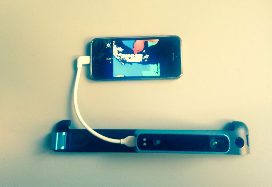
I scanned my bust using Structure Sensor connected to my iPhone in order to get the first mesh of my body.
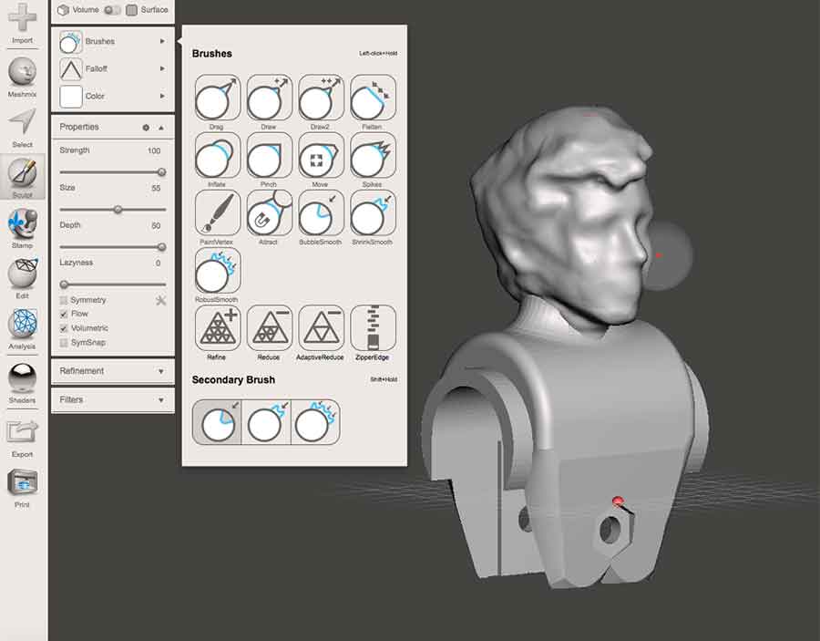
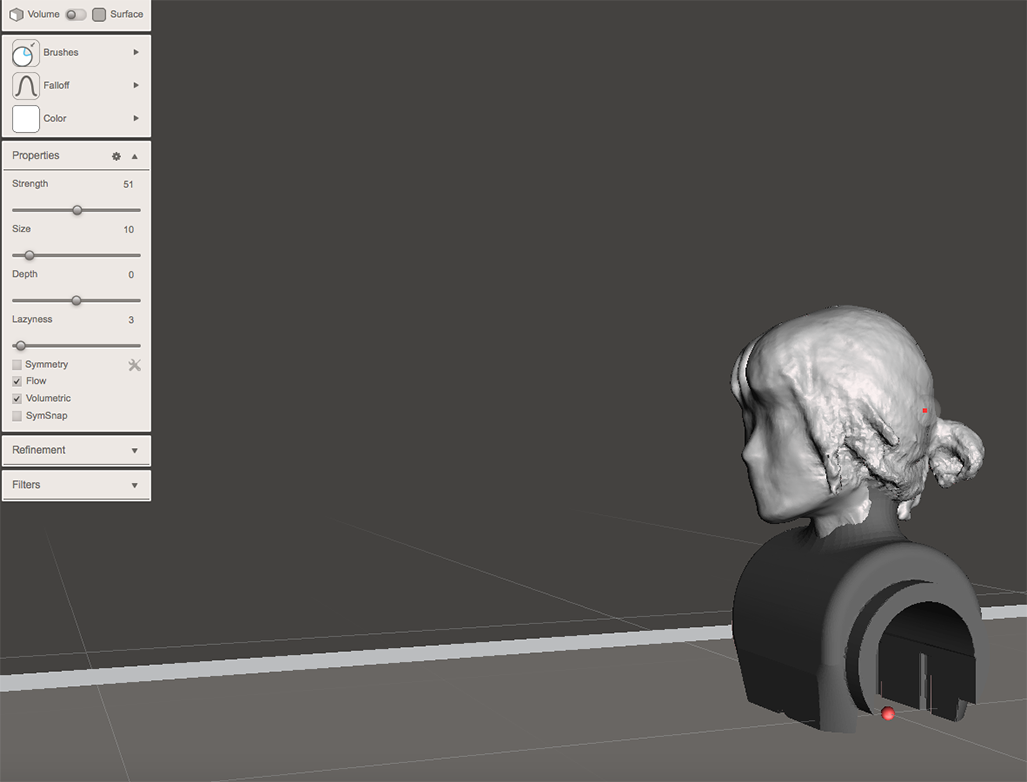
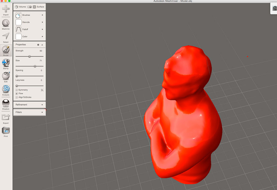
Then I used Meshmixer to refine the mesh of my initial model.With the command Edit > Make Solid you can close all holes and to get a solid model.
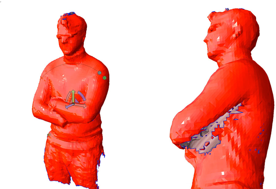
and i refined the mesh using the command Sculpt>Brushes>BubbleSmooth.
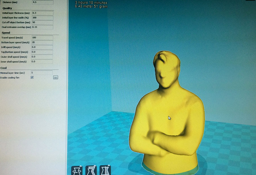
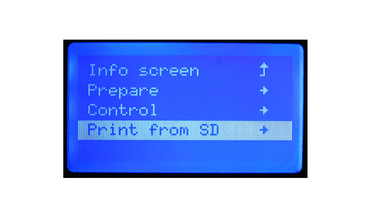
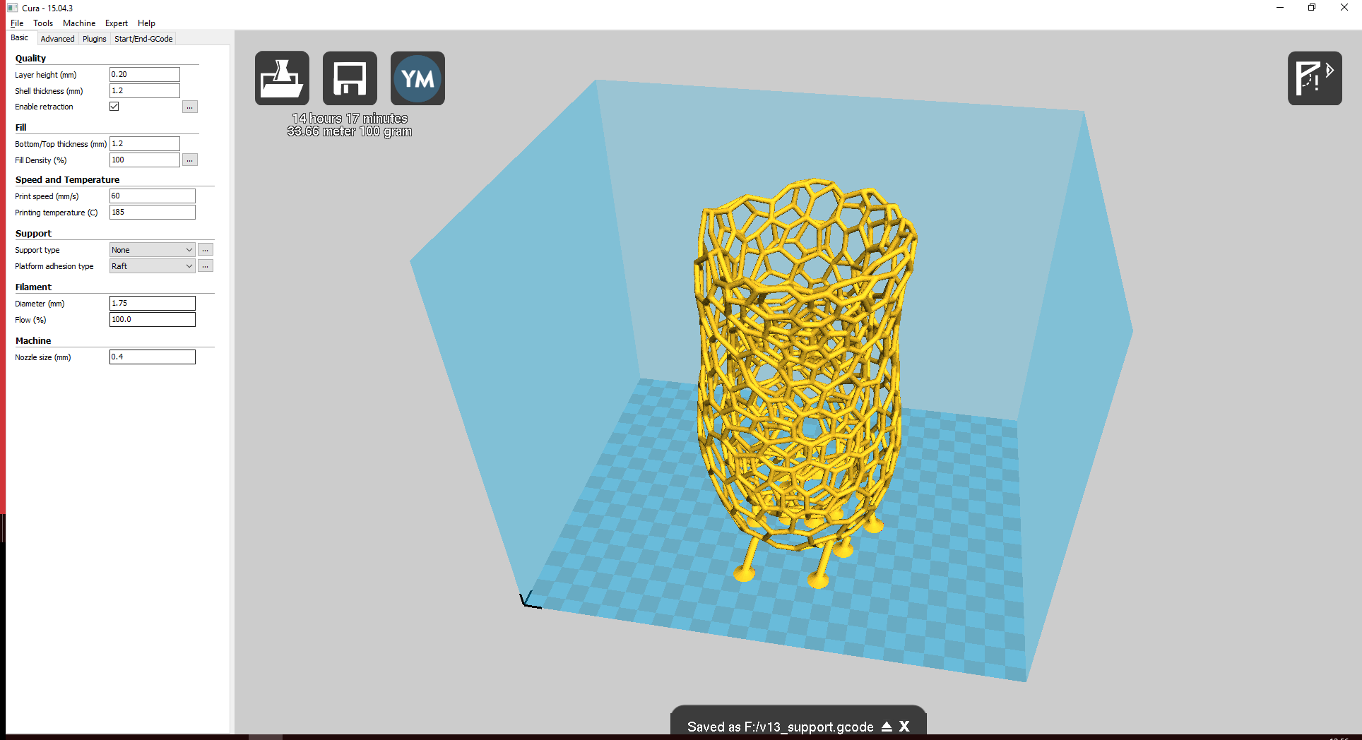
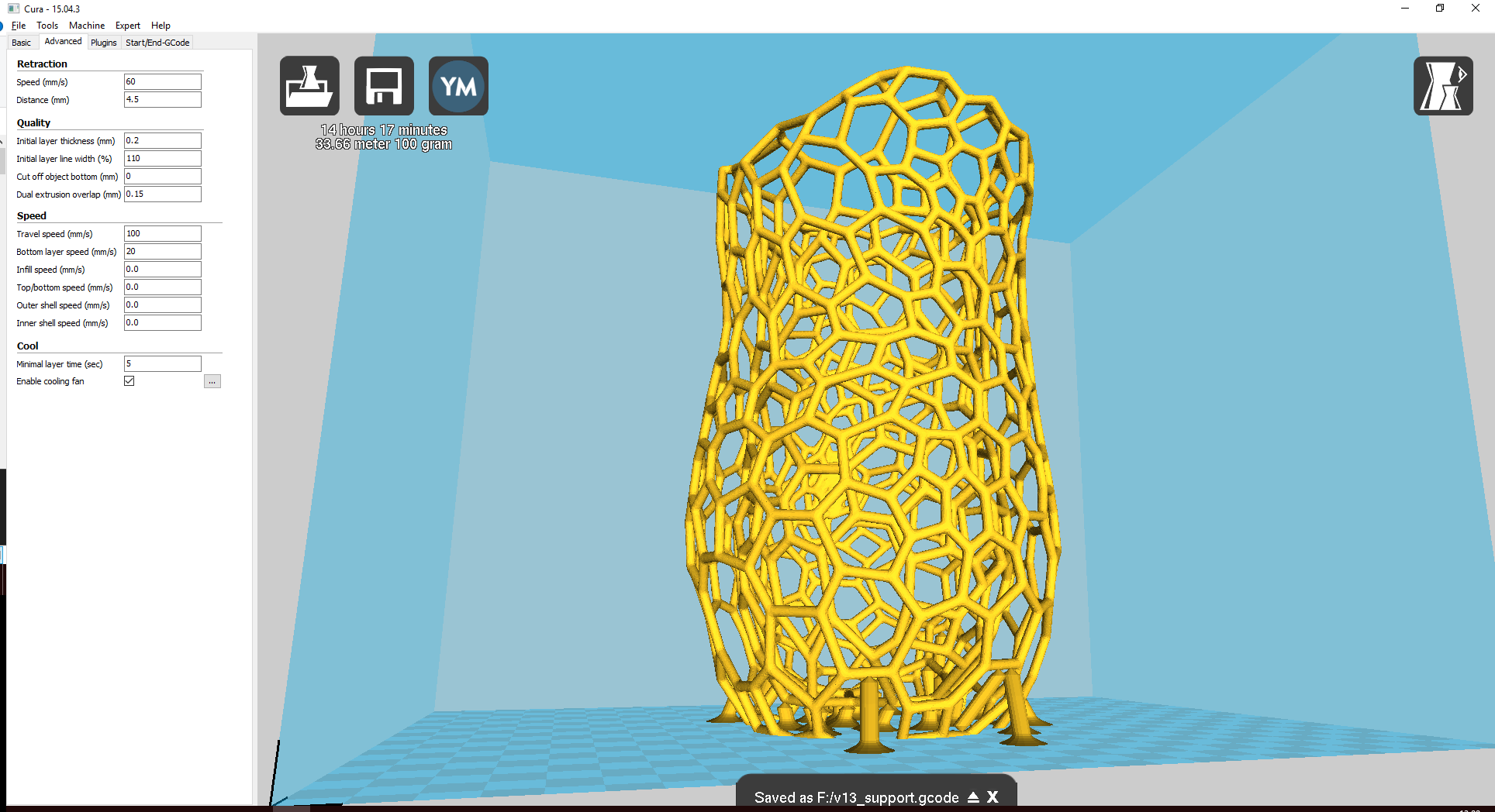
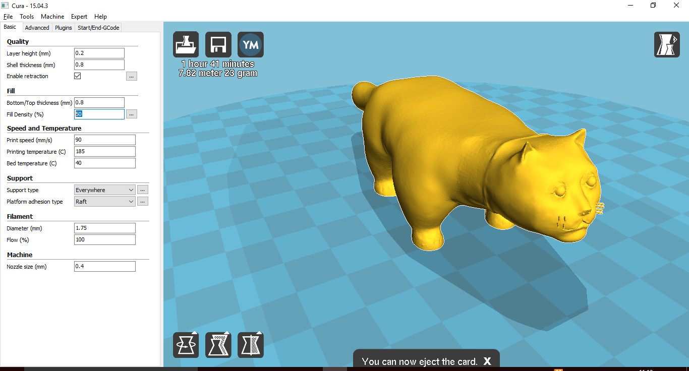
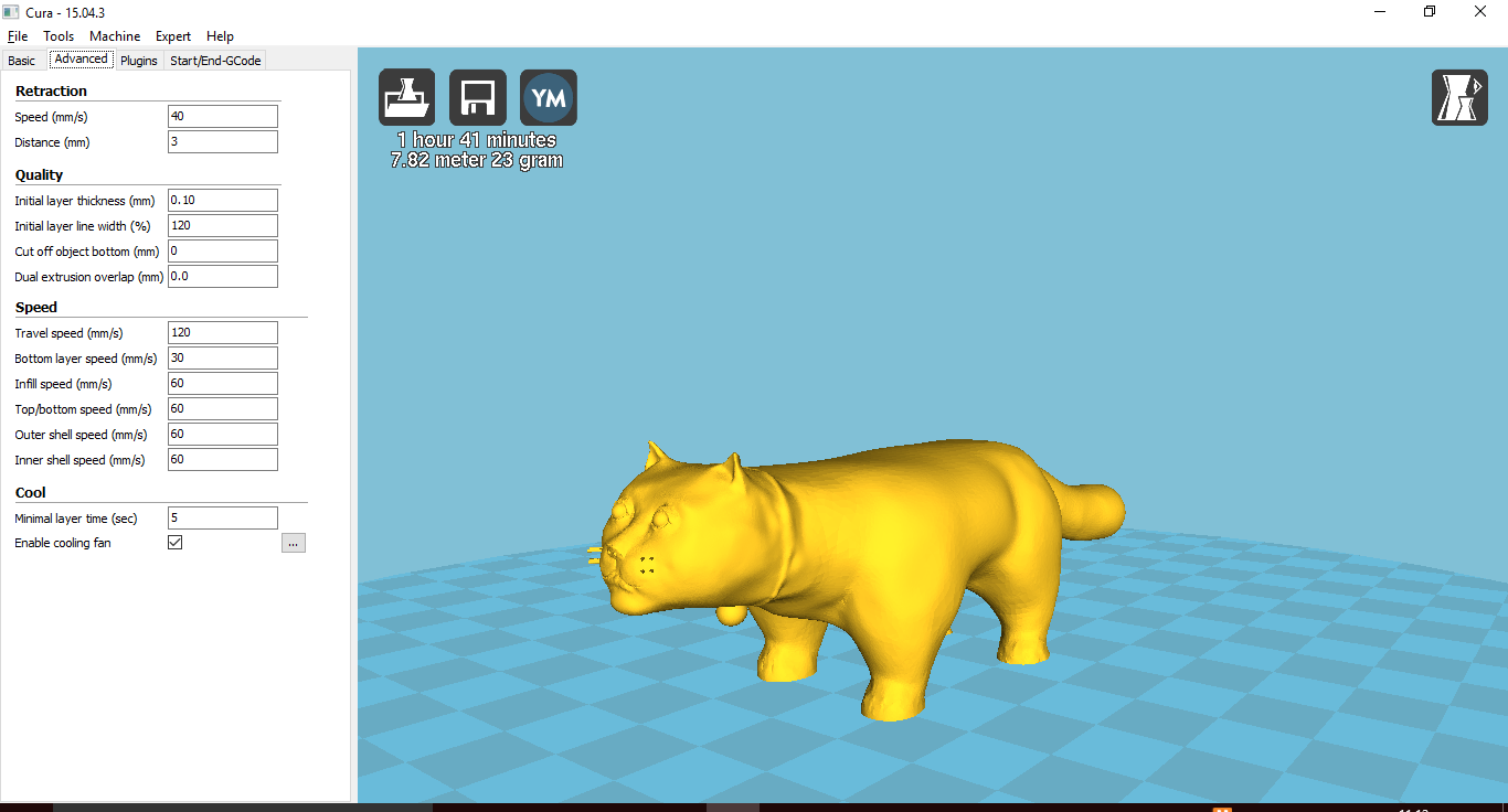
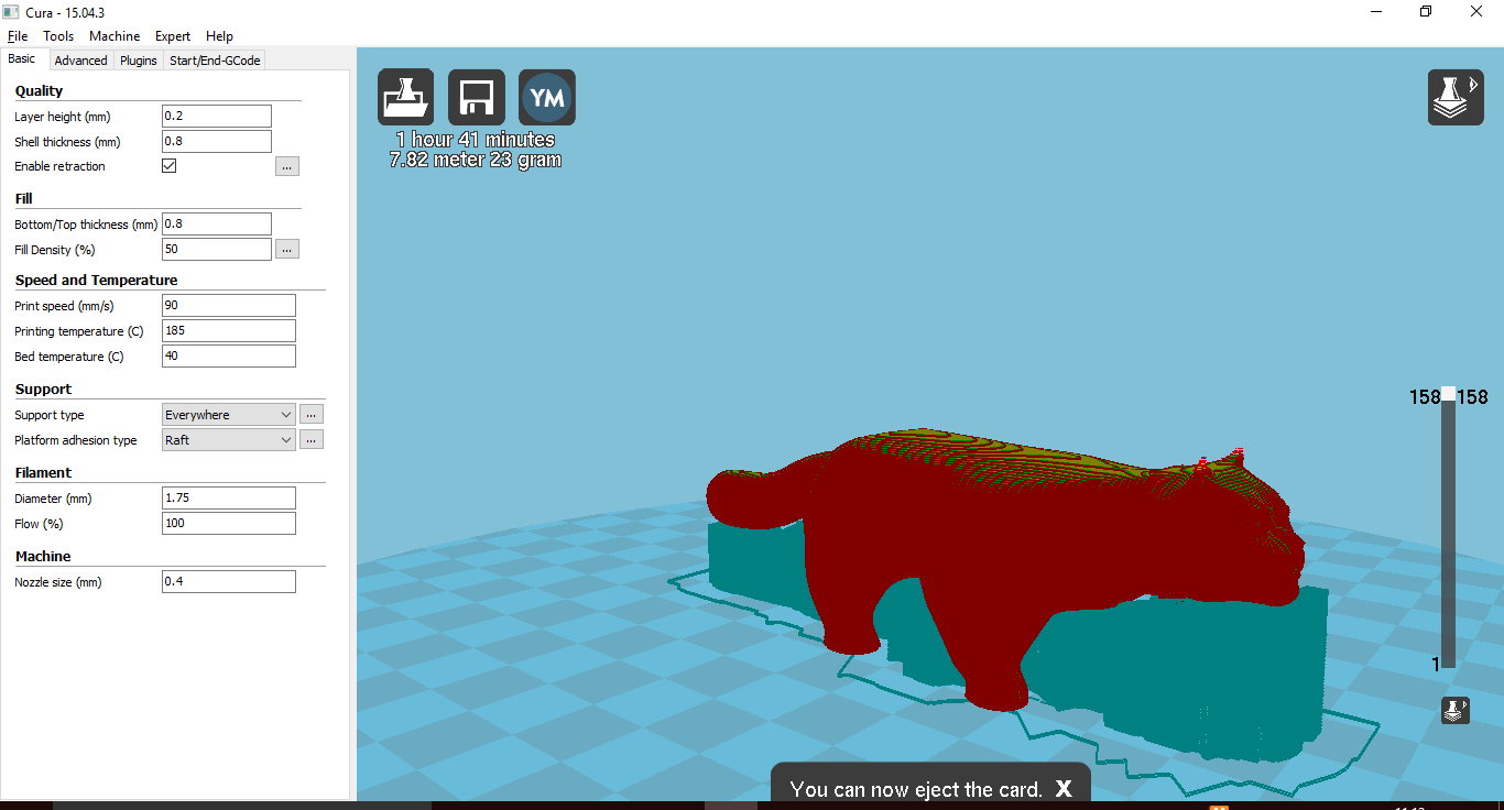
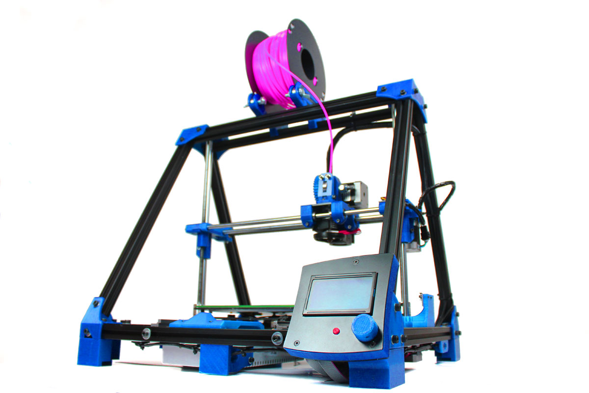
I printed my 3D model with the 3D printer BCN 3D+ and used the open source software "Cura" to generate the Gcode and copied it into the SD card of the 3D printer.
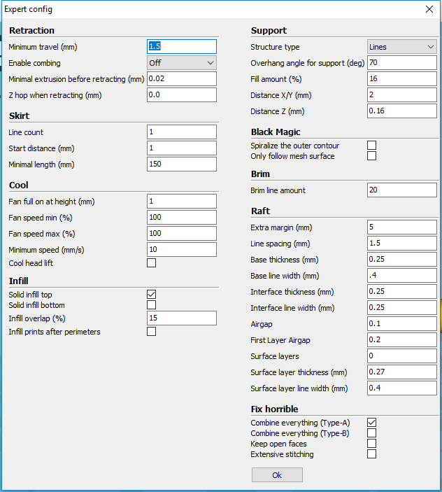
Cura settings:
Later height 0.2
Shell thickness 1.0
Bottom / Top 1.0
Fill density 20
Print speed 100%
Temperature 195 C°
Support type > Touching buildplate
Platform adhesion Type > Raft
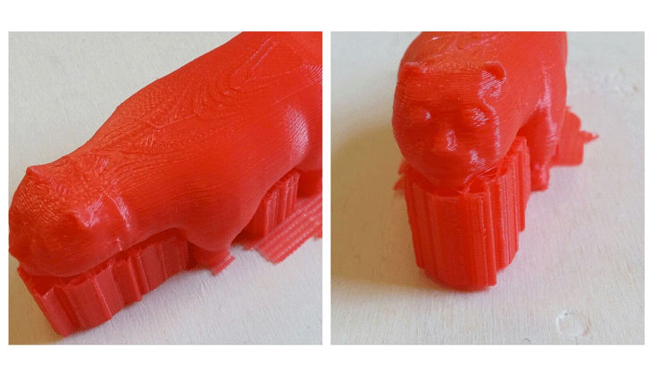
A picture of the model during the printing process.
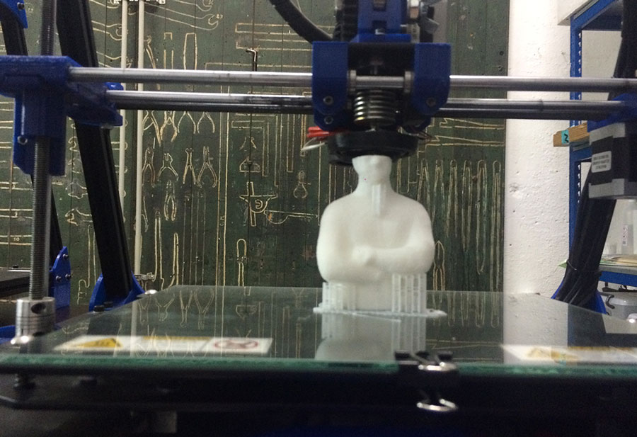
This is the result of the Print
Additive Manifacuring: According to Wikipedia 3D printing, also known as additive manufacturing (AM), refers to processes used to create a three-dimensional object in which layers of material are formed under computer control to create an object.Objects can be of almost any shape or geometry and are produced using digital model data from a 3D model or another electronic data source such as an Additive Manufacturing File (AMF) file.
Subtractive Manifacturing: Machining is any of various processes in which a piece of raw material is cut into a desired final shape and size by a controlled material-removal process. The processes that have this common theme, controlled material removal, are today collectively known as subtractive manufacturing, in distinction from processes of controlled material addition, which are known as additive manufacturing.
Use of the Subtractive Manifacturing: Large scale,wood and its derivates like MDF,foam,plastics,textiles
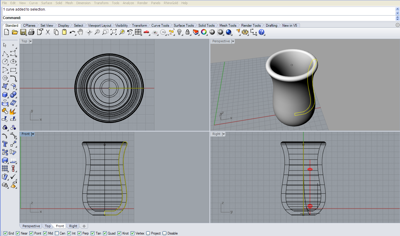
For the printing part I used the BCN3D+to create a Vornoi Vase.
I made a model in Rhino of a vase and in order to do the solid I designed a section and used the Revolve command.
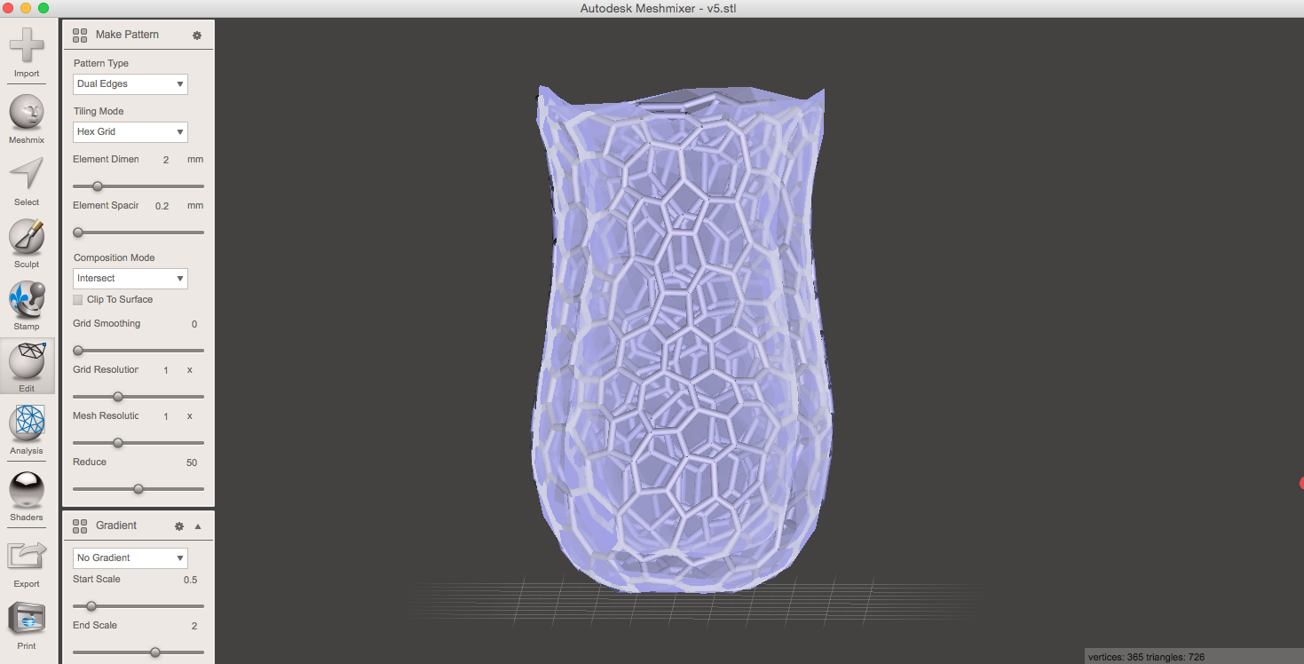
Once I imported the .stl file in Meshmixer, I reduced the polygons using a brush.
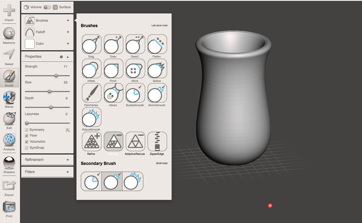
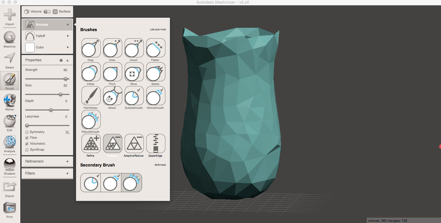
then I selected Edit > Make Pattern > Dual edges to create the Vornoi pattern.
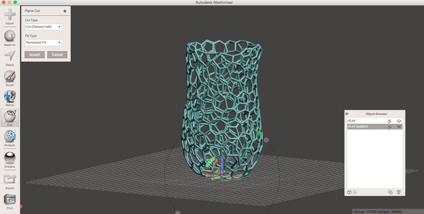
Once I got my Voronoi Vase was not completely flat so I used a Plane Cut. The Plane Cut Tool allowed me to slice the Mesh with a plane.
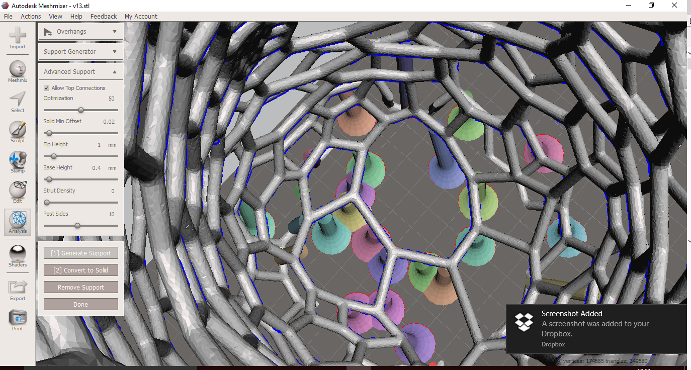
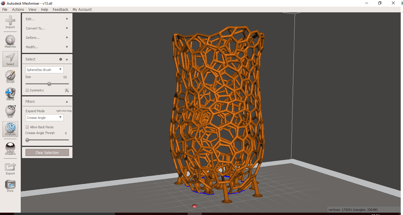
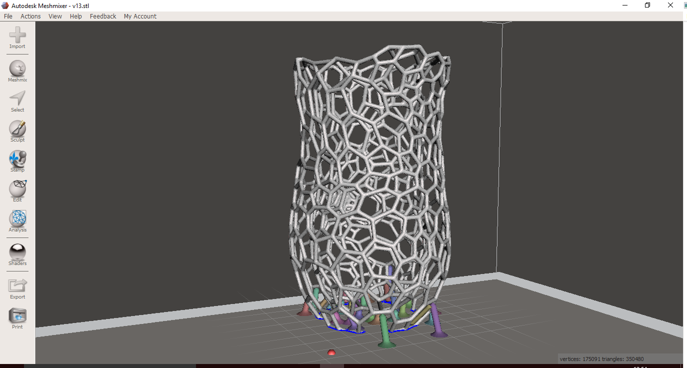
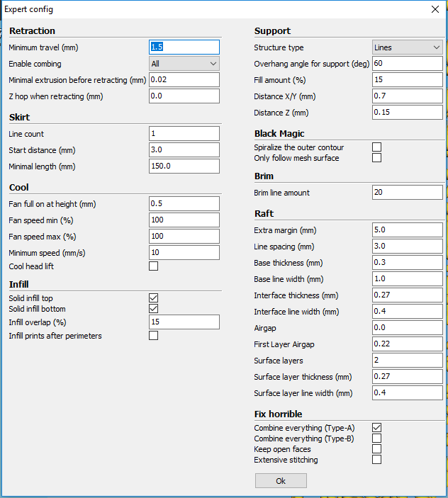
To ensure the stability of the 3D model during the printing process I added some supports to the Vase using the Support structure tool.
Before to generate the supports I needed to set the physical size of the model just going to the Analysis Tab and open the units scale tool.
In this tool just click and drag on the labels to change that dimension.than click done to exit the tool,stay in analysis tab and run the Overhangs tool.The first thing it will do is to find all the overhangs and highlight in red.Once I was satisfied with the overhang areas I selected the support all overhangs button on the bottom left and then Meshmixer generated the support structure.
Steps that I did before start printing:
Plate:
- Remove and clean the plate on both sides
- Put hair spray (for bed adhesion)
- Check leveling
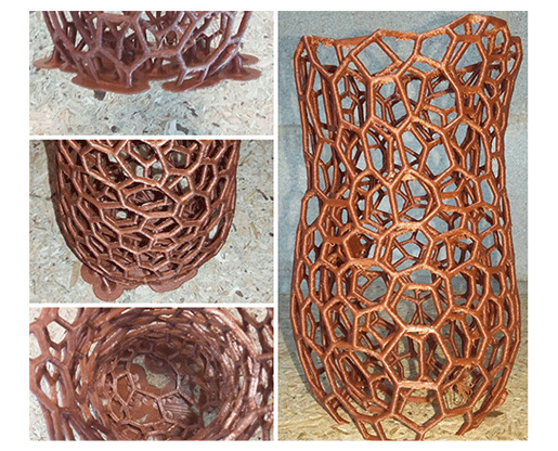
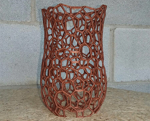
The Voronoi Vase I printed can't be manufactured by subtractive techniques because of the complexity of the shape ( complex geometry).It would need to be milled in a 5 axis CNC machine, or it would need to be divided into several parts. Even in parts, due to the "depth" of the parts, the milling bits still may not be suitable. 3D printing this form has several benefits like processing time, precision and ease of manufacturing compared to other techniques.
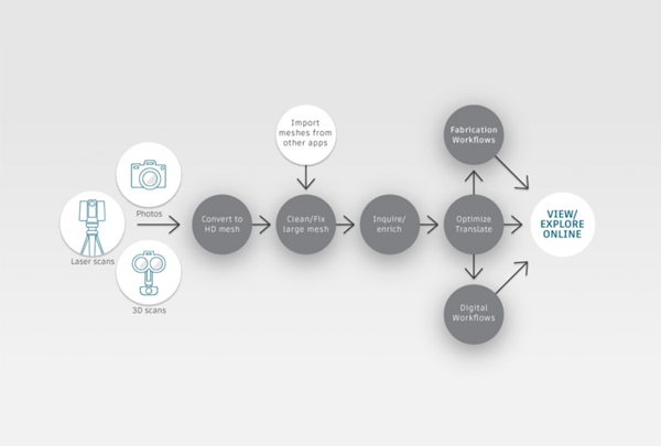
I started capturing 3D objects and 3D human body model in 2013 using my Structure Sensor and I used several applications to refine a mesh after a scan.But since I noticed, thanks to my colleague Eva Blsakova, the photogrammetry program
Autodesk ReMake, previously known as Autodesk Memento,I discovered how to turn 2D data into high-resolution 3D meshes and just using photos.
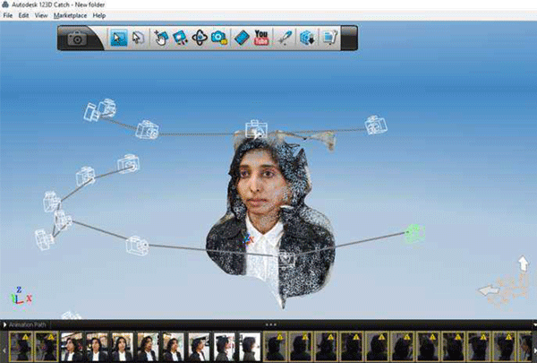
I also used with my colleague Elia De Tomasi the free software Autodesk 123D Catch for making the 3D model from photos of our colleague Janaki Ranpura and it was very helpful.
Scanning process
-take a bounch of pictures of your object ( not less than fourty)
-Send pictures for processing
-export and download the .stl/obj file
-edit with an other program
I highly recommend Autodesk Remake because it produces top-quality digital results and once the mesh is ready it can be cleaned up, fixed, edited, scaled, measured, re-topologized, decimated, aligned, compared, optimized and animated.
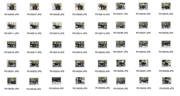
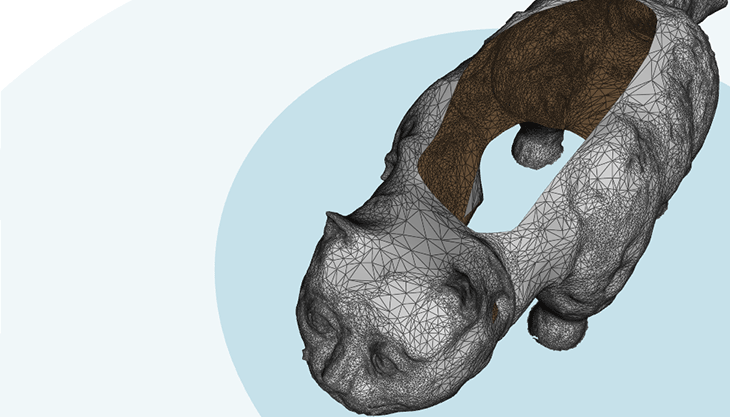
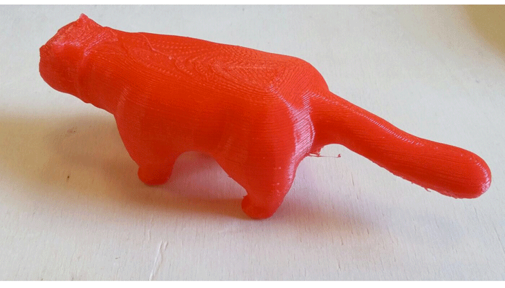
The model shown below is a Fernando Botero's sculpture simply called El Gato del Raval that I captured using my Iphone and I took about 50 photos of this sculpture.
*Note: The more photos you upload in the cloud, the better resolution of the model you get.You can upload up to 250 photos but with the pro version.
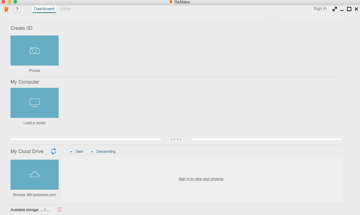
Basically Remake will send photos to the cloud and algorithms will convert photos into the 3D model.After a while, I received an email telling me that my 3d model was ready and when I opened Remake looking at My Cloud drive the model was ready for download.
In Dashboard under My cloud Drive Hit the blue arrow and define the location wher you want the model to be saved, after saving it to the desktop the model will appear in My computer to be open.
When loading a model just set first the scene orientation correctly, to do that select the Set scene upright(just orient the model using the gizmo).
edit mesh:
the first thing I will do is clean up the environment:
-select the lasso tool, hold the left mouse key painting around and then holding delete key on the keyboard to delete that area.
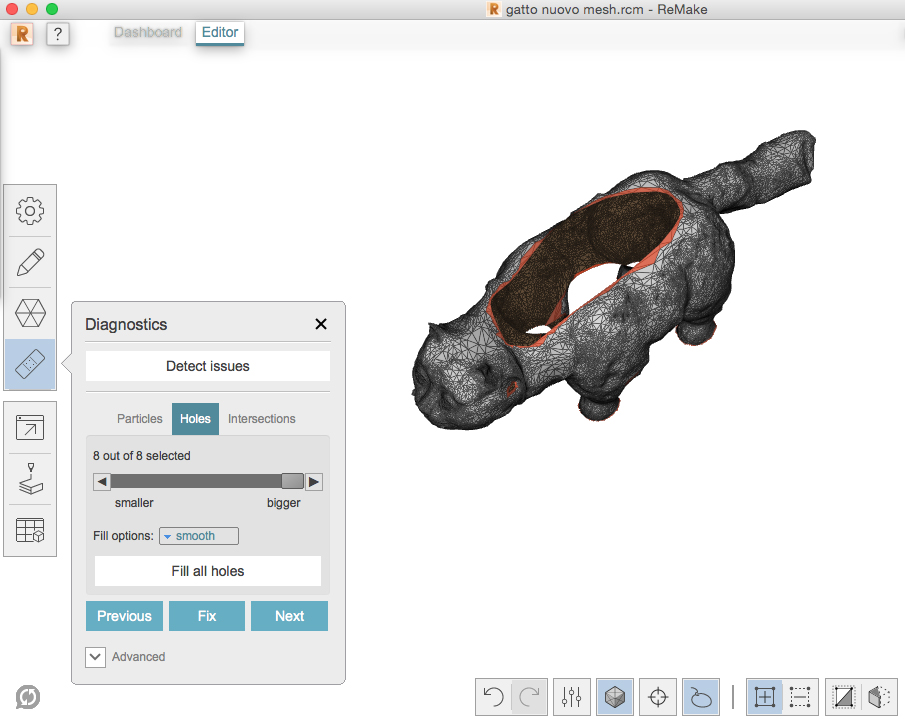
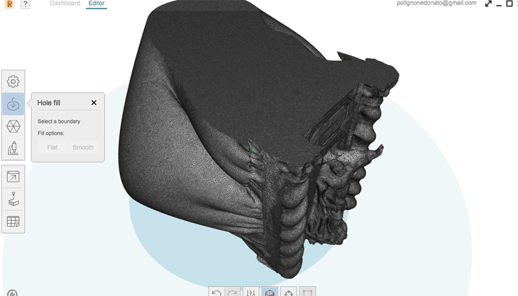
As you can see below, the model presents a huge gap in the geometry and it needs to be fixed.
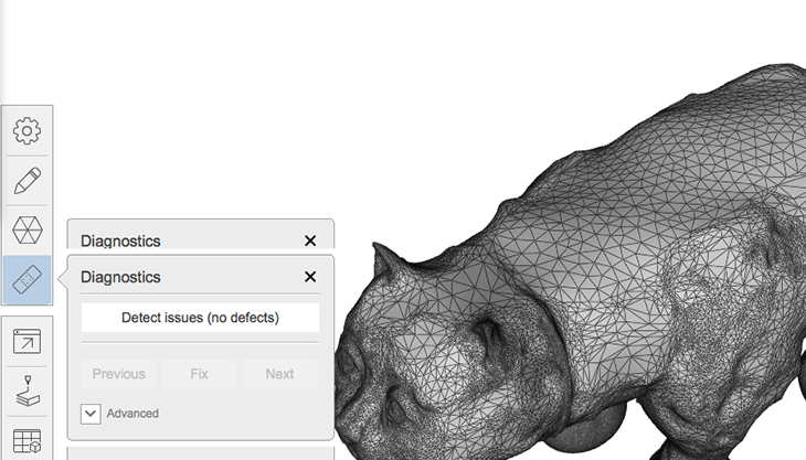
Remake will check for double meshes,inverted meshes,meshes with 0 thickness,spikes particles tunnels, all kinds of problems that a 3D model might have.
If you want to fix some issues of the model like holes, just click in the diagnostic ( plaster symbol in the menu) and you can fix all holes in the 3D model.
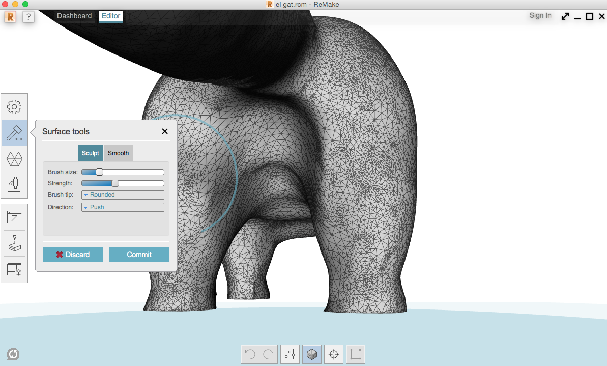
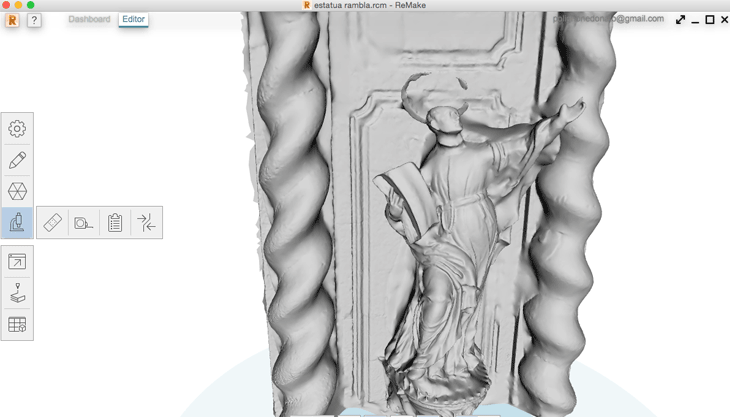
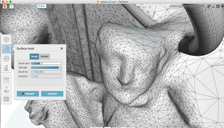
Now the model is ready to be printed but if you want to refine some parts using the Sculpt tool just go to surface tool (symbol hammer) and select sclupt, that will enable you to edit and sculpt areas of the mesh. I will set the brush size slightly big and I start with holding the left mouse click and modifying that surface.
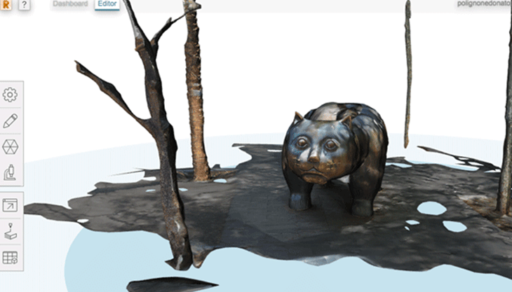
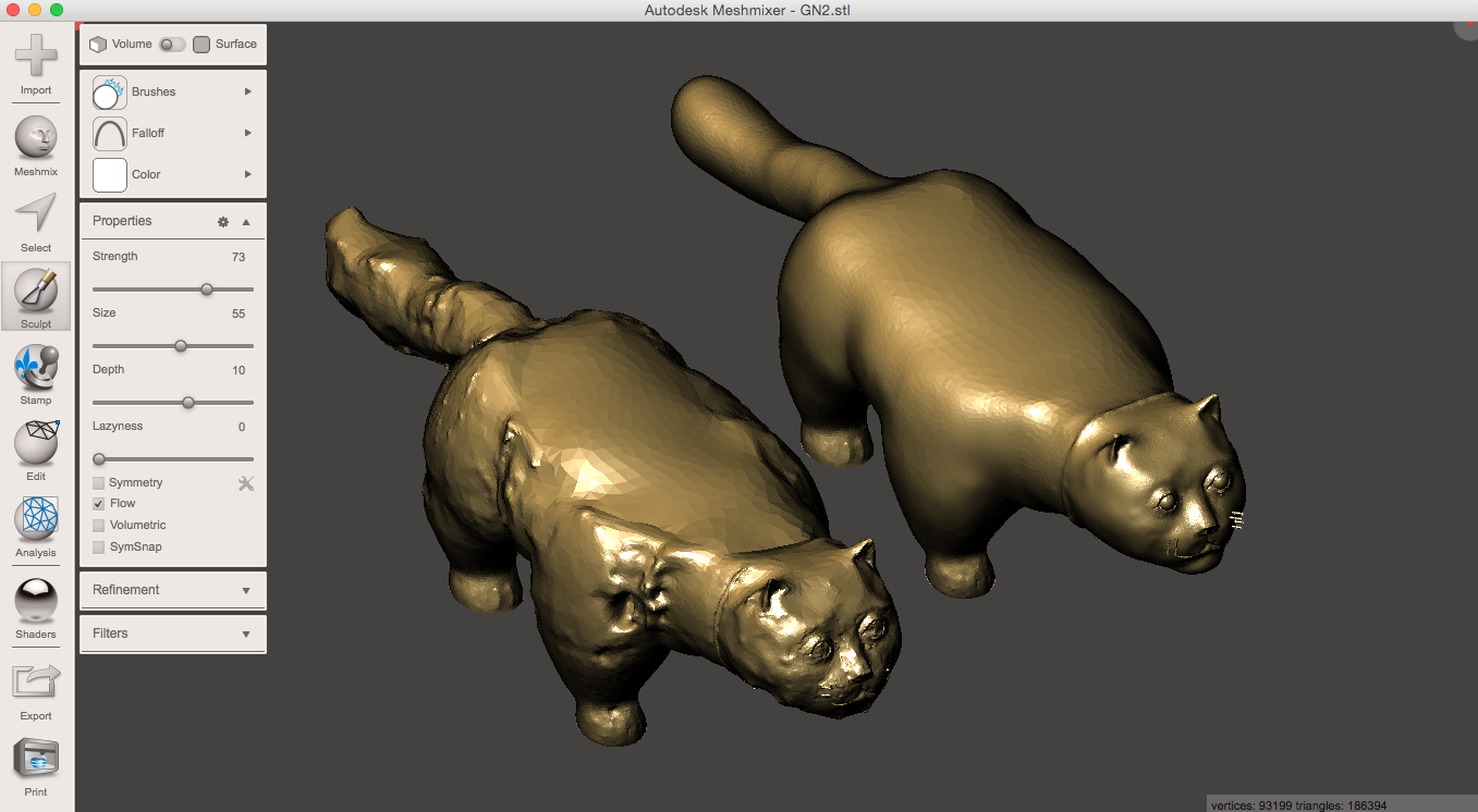
As you can see in the image below in Meshmixer I imported the first mesh(in light gray) which I obtained with Remake and then I used all kinds of Sculpt tools(brushes) to refine the first Mesh.I could use the sculpt tools of Remake but I have already experienced with Meshmixer's brushes.Below the final result after a long work of mesh refinement.
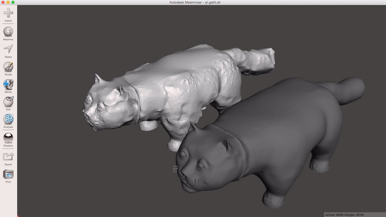
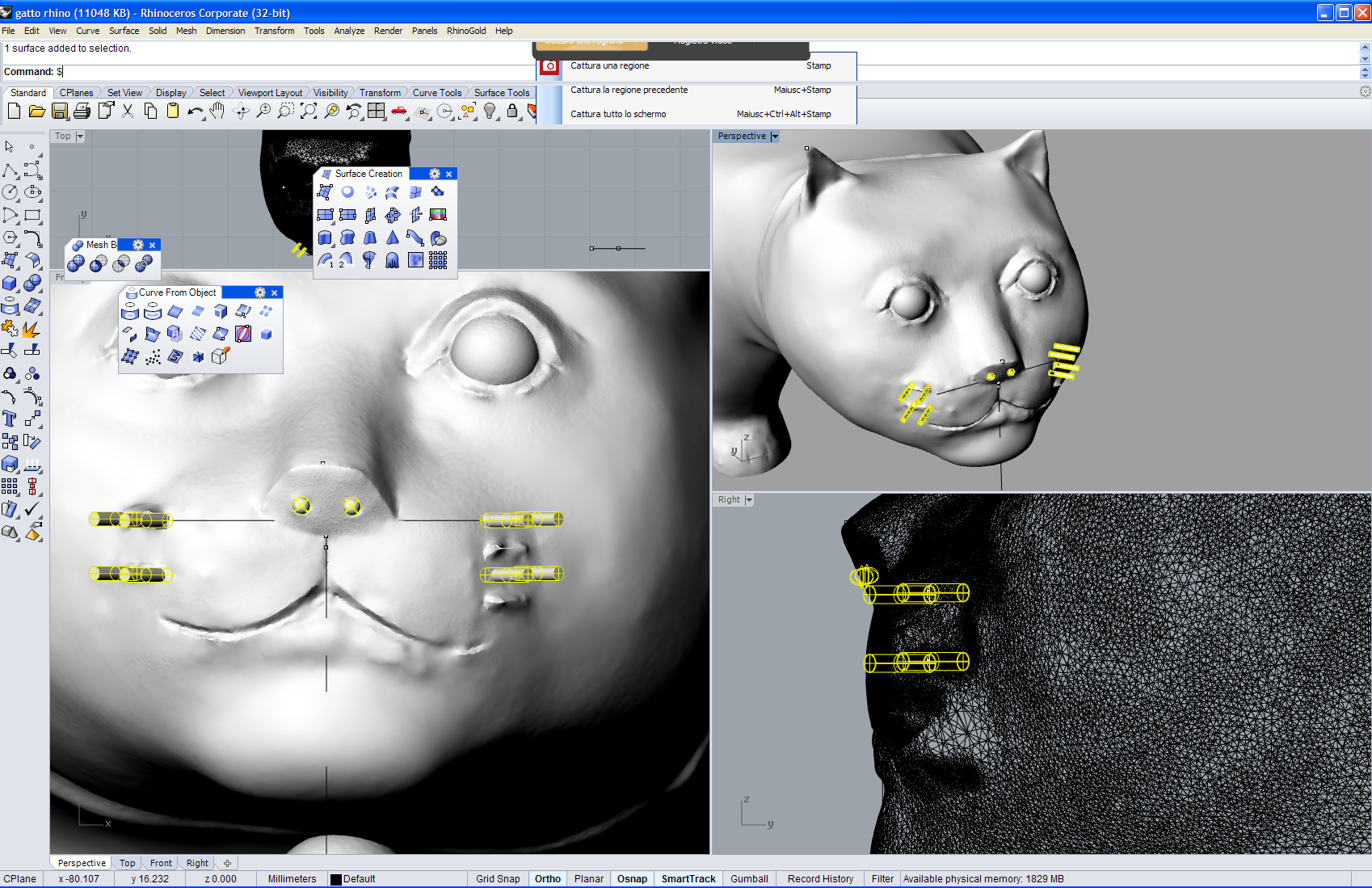
With the program Rinoceros I added some more details like the cat's whiskers lost during the 3D data acquisition because of the reflectivity of the material.After that the .stl file was ready to be printed
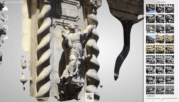
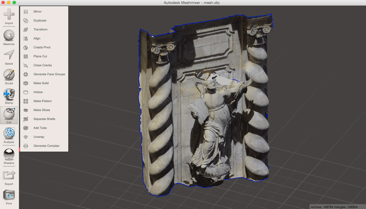
Autodesk ReCap 360 is both a Web Service and a Windows application which I used to get the 3D model of the statue of San Ignacio de Loyola made by Andreu Sala at Iglesia de Belèn in Barcelona.
Note: Register first a Free Autodesk Account, this will give you access to the free ReCap 360 Web interface and 5GB of free cloud storage on Autodesk’s A360 Drive.
Make the photos To get a good mesh Take usually a minimum of 20 photos in a 360° circle so you’ve covered very angle in my case I could just take photos in 180° because the wall of the church and also take a minimum of 6 photos from a down facing angle in a 360° circle.The more the better even if using the free version you can just upload maximum 50 photos of the object. - Go to recap360.autodesk.com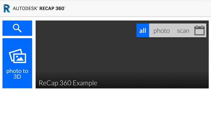 -Enter a project name " Statua Rambla 180"
if you want To download the mesh go to your 360 Drive by visiting a360.autodesk.com/drive (log in and open the folder with the same name as your ReCap 360 Project, after that click the file name that ends with .obj.zip and click the download.Open the 3D model
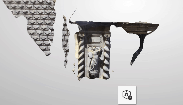
As I explained before using Meshmixer you can delete some unwanted extra points or parts of the scene with this command: Select tool > lasso or brush to select just a small area, double click to select all or "I" on keyboard invert and delete key to remove.
The command Fill holes allows to fill holes in a mesh just selecting a hole to be filled, hoover close to the boundary of the hole and once highlighted, click to select Pick filling method (smooth or flat PRIOR to closing the hole).
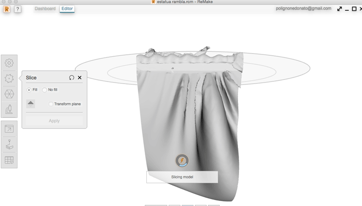
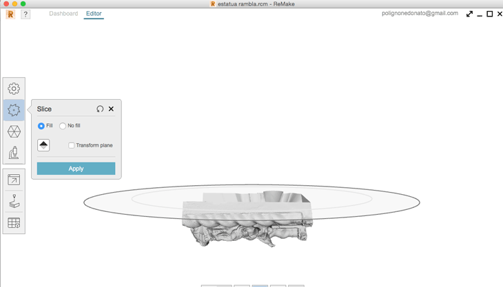
With Slice and fill a plane cuts the model with clean edge, leaving the sliced surface open (no fill) or filled (Fill).
I lost some details in my mesh so using Rhinoceros I used the command MeshBooleanUnion to combine 2 meshes.
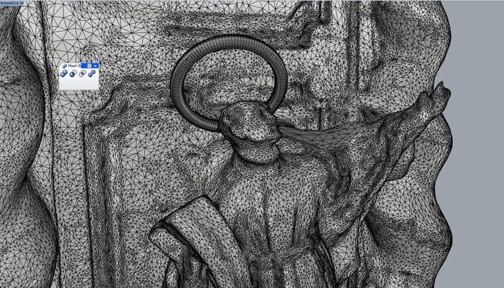
Then I switched to Remake again to Sculpt with a brush to refine some details.
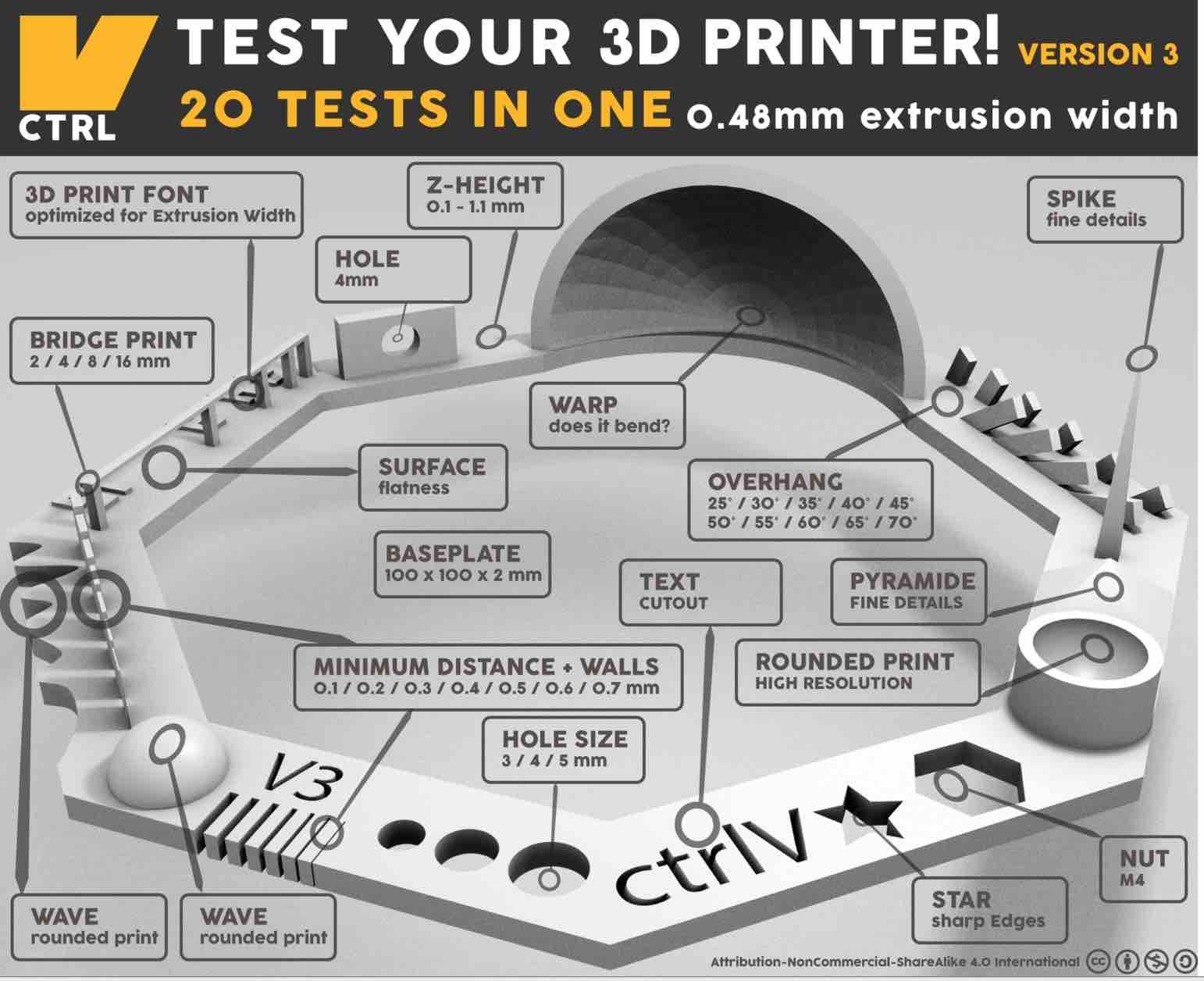
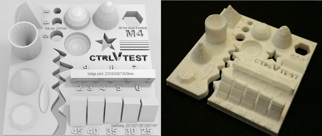
We've downloaded a standard test on Thingiverse and printed one. We discussed several points to look for when printing and how to solve some of the problems. This is the test list and what we can conclude from it:
Warping
Size: the object is 4 x 50 x 50 mm (baseplate) — measure with a caliper
Hole size: 3 holes (3/4/5mm) — measure with a caliper/drill
Nut size: M4 nut should fit perfectly — insert an M4 nut; it should need a little pressure
Fine details: pyramid, cone, all numbers — check if all things look nice and smooth
Rounded print: wave, half sphere — check if all things look nice and smooth (not every printer handles round things similar, e.g, it will be split in polygons) see here for more details
Minimum distance between walls: 0.1/0.2/0.3/0.4/0.5 mm — depending on your nozzle size and slicer settings you will get different results
Overhang: 25°/30°/35°/40°/45° — depending on printed material/cooling, these will not be as seen on the rendering provided
Flatness: all flat areas — these should be flat with no gaps
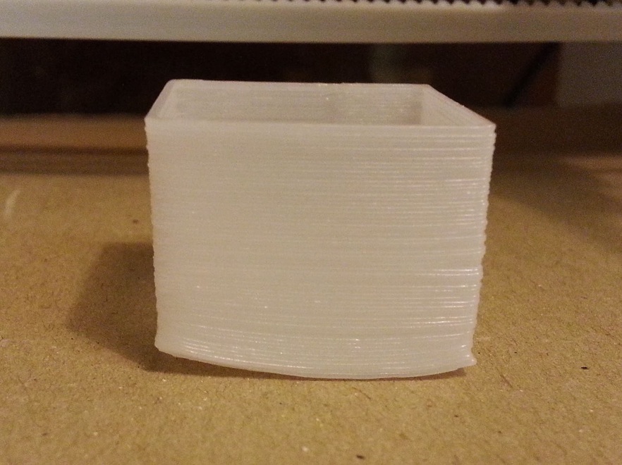
Warping:
When the corners of the print start to bend. Here are a couple of the methods to reduce the warping effect
 Warping
  Skanect
 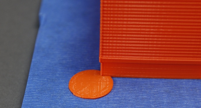 Pads
Pads 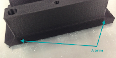 Brim
Brim 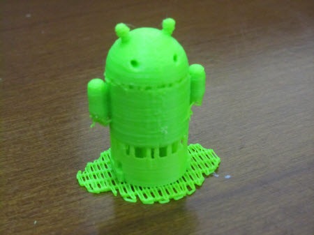 Raft
Raft Retraction
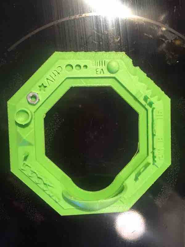
 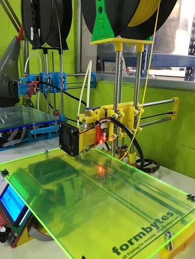 We used this test (below), but we did it wrong because we scaled the model, do not scale the model:
The printer settings should be set to its lowest possible layer height (0.1 mm in most cases), with an infill of approximately 33%, in order to ensure that all the details come out correctly. Once the object has finished printing, you can check to make sure everything is calibrated and working correctly by using the following methods below:
Size: the object is 4 x 50 x 50 mm (baseplate) — measure with a caliper
Hole size: 3 holes (3/4/5mm) — measure with a caliper/drill
Nut size: M4 nut should fit perfectly — insert an M4 nut; it should need a little pressure Fine details: pyramid, cone, all numbers — check if all things look nice and smooth
Rounded print: wave, half sphere — check if all things look nice and smooth
Minimum distance between walls: 0.1/0.2/0.3/0.4/0.5 mm — depending on your nozzle size and slicer settings you will get different results
Overhang: 25°/30°/35°/40°/45° — depending on printed material/cooling, these will not be as seen on the rendering provided
Flatness: all flat areas — these should be flat with no gaps
download test
Different problems while printing (besides the scale):
Warping, how to avoid it:
 * Layer hight (recommended 0.2 or 0.3)
 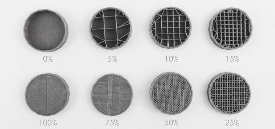 * Add brim, printing spots, raft (in case the piece has few points of contact) or something manually as little horizontal lines, another option is heating the space or the platform, so that the piece doesn't cool down so quickly.
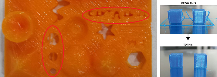
Before preliminary print a Test sample+was made. This is to check various parameters such as hole size, nut size, fine details, rounded prints, minimum distances, overhangs, and flatness. The printing test had some warping; this could be avoided through adjusting layer height(recommended .2 or .3); fill density (recommended 15%-25% depending on the piece); adding brim, print spots (can be done manually on 3d) or in extreme cases rafting (not suggested)
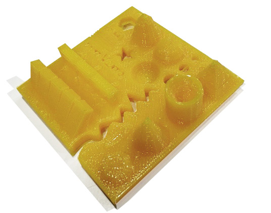 We used a standard 3D printing test piece from thingyverse. The printer settings should be set to its lowest possible layer height (0.1 mm in most cases), with an infill of approximately 33%. This ensures details to come out nicely.
Methods to test finished 3D printed object:
We used a standard 3D printing test piece from thingyverse. The printer settings should be set to its lowest possible layer height (0.1 mm in most cases), with an infill of approximately 33%. This ensures details to come out nicely.
Methods to test finished 3D printed object: 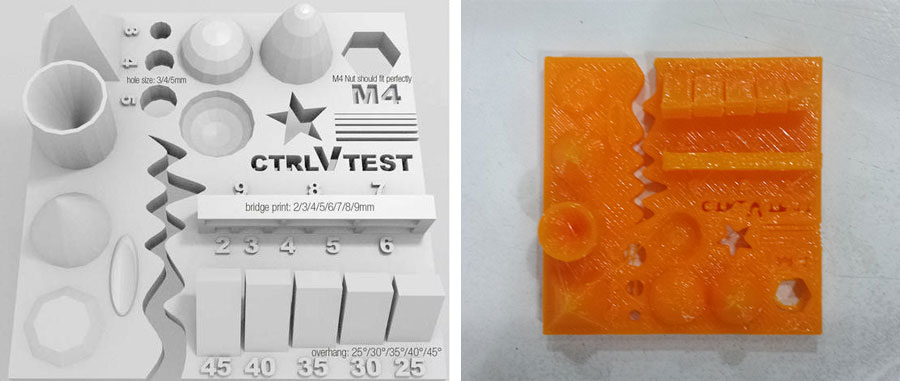 the file and our result
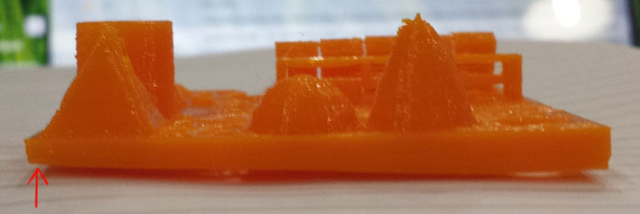
 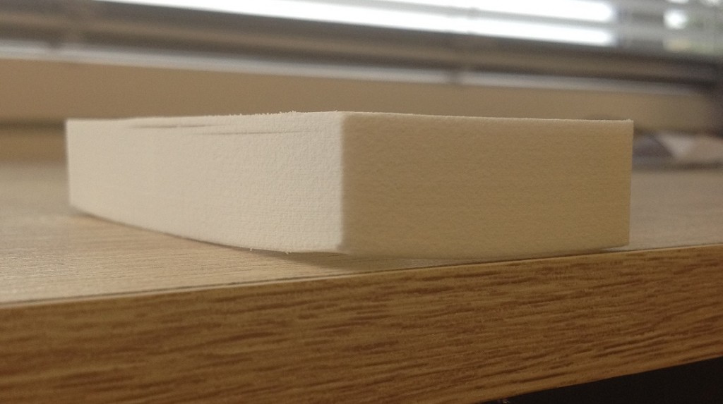 not a straight base (photo from 3dprint-nz.com)
Methods to reduce the warping effect:
not a straight base (photo from 3dprint-nz.com)
Methods to reduce the warping effect: 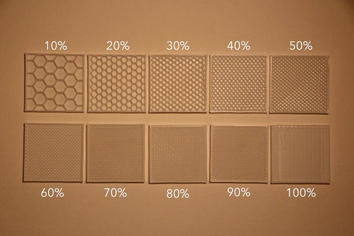 fillament volume (photo from enablingthefuture.org)
2)Retraction Fail: need to change retraction settings of the printer
fillament volume (photo from enablingthefuture.org)
2)Retraction Fail: need to change retraction settings of the printer 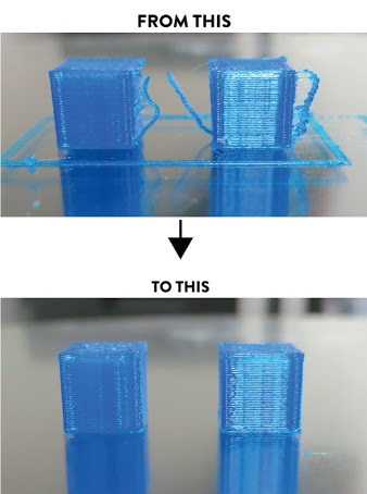 Material Filament Material PLA Temperature 190~220 Filament Colors Yellow, Green, Orange, Gray Filament diameter 1.75mm
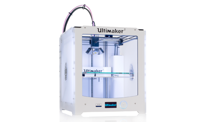
 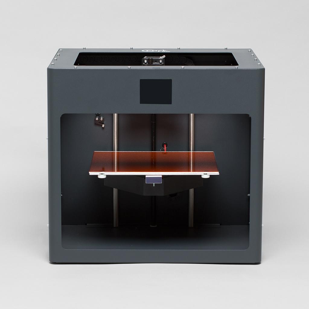 1 Uli2go from the Netherlands
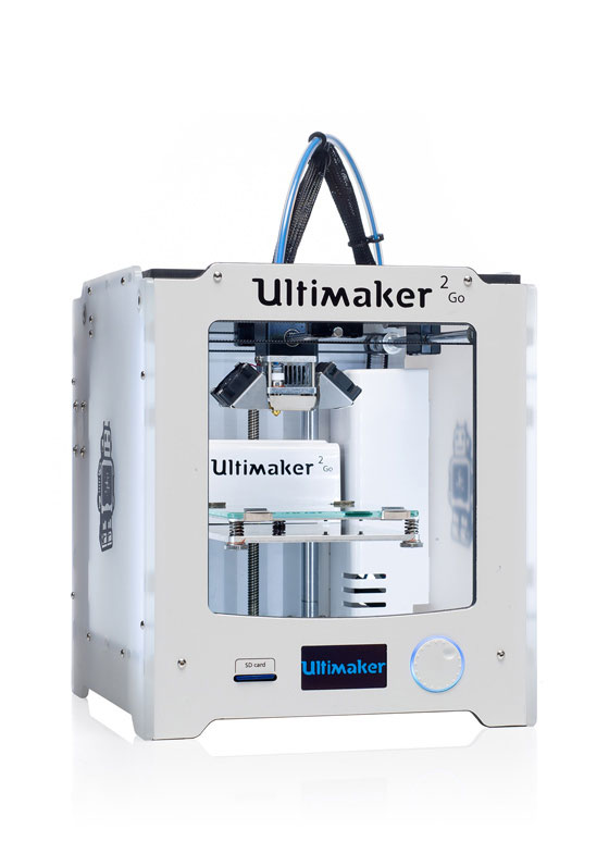
 and 3 Micos from the US in my lab.
 I already spend quite some testing the limits of these printers.
For this assignment I downloaded a test from test from Thingiverse
to test the limitations of my printers.
The test piece from Vctrl takes about 1:30 to print and includes 30 test.
I already spend quite some testing the limits of these printers.
For this assignment I downloaded a test from test from Thingiverse
to test the limitations of my printers.
The test piece from Vctrl takes about 1:30 to print and includes 30 test.