Design and build a wired &/or wireless network connecting at least two processors.
Software Used:
Eagle
Gimp
FabModules
So the big challenge for this week is to understand how we can talk between devices via wireless or wired connection, connecting at least two processors.
Professor Niel started this class by explaining what were the advantages of net-working. First of and most obvious is the location factor then the distributed labor, meaning, in a big project instead of having just one processor doing all the required tasks you would have many working in parallel doing one task each.
Another good reason for applying this system is its modularity and therefore easier debugging and replacement in case of need without disturbing the rest of the tasks avoiding interference.
A system built by several subsystems that work together sometimes can be a great method for better organizing the architecture of the electronics even if physically they would be placed together.
Simplifying, what this means is that all nodes in a network would share Transmit- TX and Receive - RX lines that would be connected to a host that is able to talk and listen.
Asynchronously all nodes would receive a signal from the host and while the target node would be active the other nodes would be inactive and so the host thinks he's only talking to one, while, in fact, there are several processors in the net.
Along with the rest of the class examples we were given, about serial communication and how in the code the ports should be defined so that all can listen but only the identified one can answer.
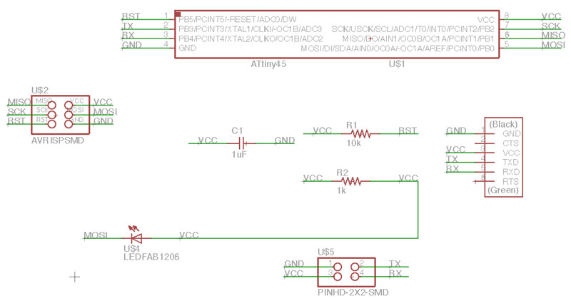
Board Design:
I designed my boards using Eagle.
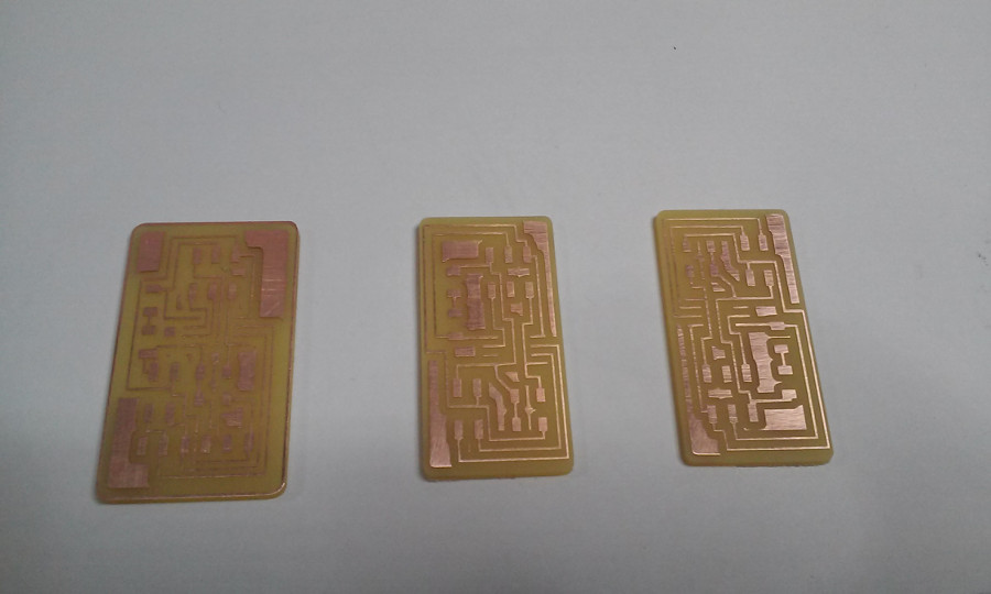
Milling Board:
After Designing it I milled It in the modella because I wanted to get Acquainted with the Fabmodules to control the machine.
Start the fabModules from the terminal with "fab", choose input format and the machine(Output Process)
Change x/Y origin using the "move to xmin,yin" and the Z manually or the modella"" Up/Down""
Load The desired Image; choose in defaults the Milling bit you are gonna use; click "make.path"; "make.rml"
Mill it!
Programming board:
With the C file and make file on the same folder I used the terminal to uploading the code.
On the terminal I located my folder with the C and make files.
On the C file you need to change the #define node_id '0' for each node.
I used, for the Master board: #define node_id '0'
For the first node: #define node_id '1'
For the second node: #define node_id '2'
And type the "sudo make -f hello.bus.45.make program-avrisp2" or "sudo make -f hello.bus.45.make program-usbtiny". For each board.
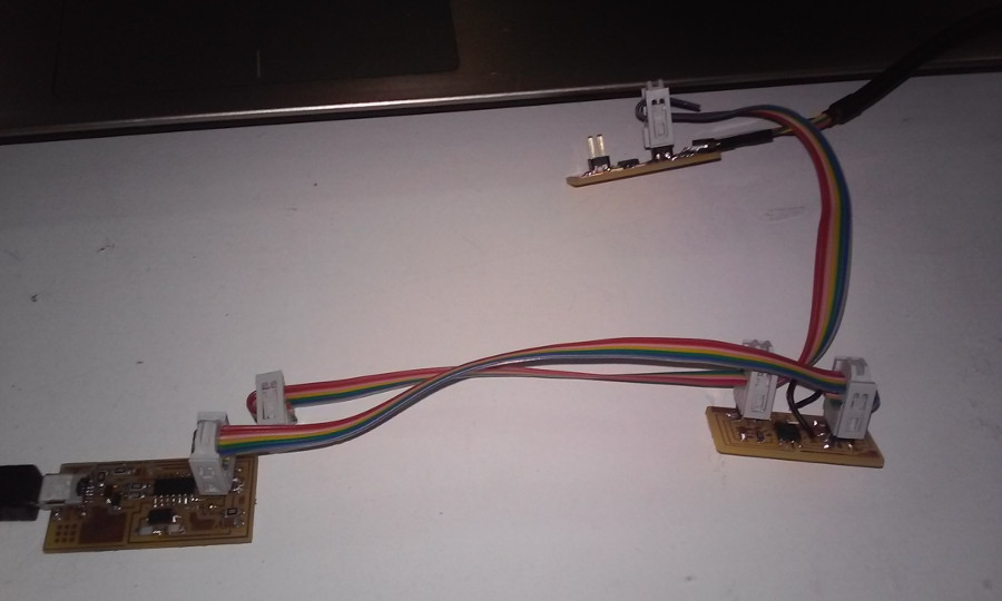
Connect the bridge board on one side to the FTDI and on the other to the FabISP or AVRISP and program it with the make file and C file that you change the node id to 0
Connect the first node to the bridge with the network cable and the FabISP or AVRISP and program it with the C and make file that have the node id set as 1
Finally, you connect the the last node and follow the same workflow as node 1
Next, Open the Arduino IDE, and click on the Serial Monitor button. On the Serial Monitor window type 0, 1 or 2 and press enter after the selected node you typed. Then you should get your boards react.
The node selected should blink twice and get a response on the serial monitor window.