Add an output device to a micro-controller board you've designed and program it to do something.
Software Used:
Eagle
Gimp
FabModules
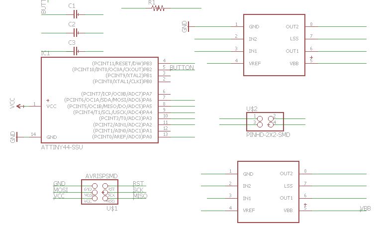
I started by basing my board design on Neal's Design but since I wanted to use both DC motor or a Stepper motor dew to the fact that we are using a lot of recycled material on the Precious Plastics Project and we don't know what type of motor we will find on the scrap yard this would be a good solution, to have a board that could run both.
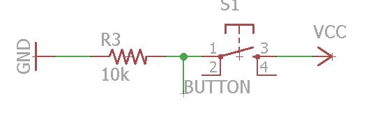
To accomplish this, the trick is on the Programming more than in the board it self since the electromechanical phenomenon are very similar. To achieve it I thought on adding a button so we could exchange between the program for the Stepper and the one for the DC Motor.
Board Design:
I designed my boards using Eagle and added a button to Neals design.
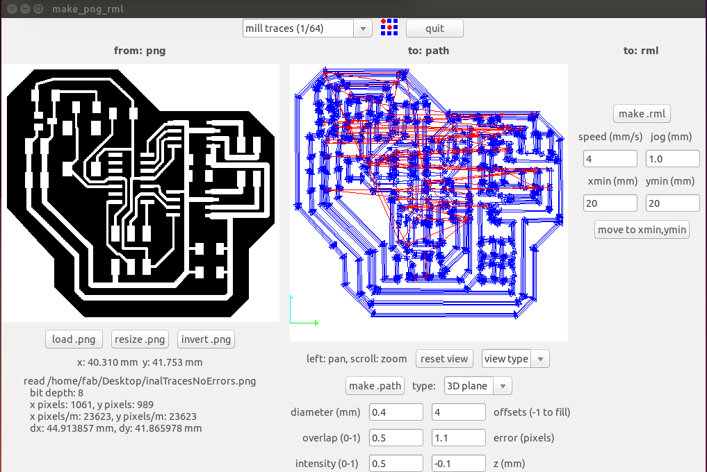
Milling Board:
After Designing it I milled It in the modella because I wanted to get Acquainted with the Fabmodules to control the machine.
Start the fabModules from the terminal with "fab", choose input format and the machine(Output Process)
Change x/Y origin using the "move to xmin,yin" and the Z manually or the modella"" Up/Down""
Load The desired Image; choose in defaults the Milling bit you are gonna use; click "make.path"; "make.rml"
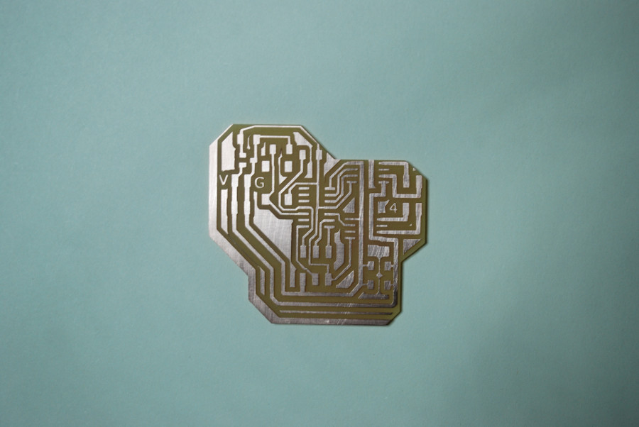
Mill it!
Programming board:
First board I managed to program nicely after finding out all the problems it had, from a Pin output from attiny not connected to the Input of the H-bridge to the LSS connectors of both H-bridges not being connected to GND.
But due to the patches I made after programming the board, the motor worked for 5min but it ended up burning the board.
After Solving this mistakes in Eagle I milled and stuffed the board again, This time the first time I tried to program the board It Gave me a error 1.
After changing the port that the ISP was connected I managed to program the board. This way I new my board was working and could now start to work on the new program for both Stepper and Dc Motor in one Drive.
To accomplish this I had to change the output port in the Dc program to that of the same in the Stepper (A1 and A2).
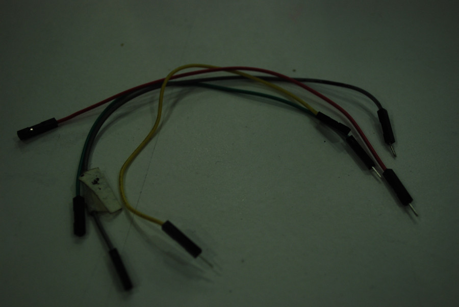
I had to make some cables so I could connect the power source and the motor to the board. You have to be careful how to connect the board to the H-brige and so I look up the A4953 Datasheet To understand how tj H-bridge works
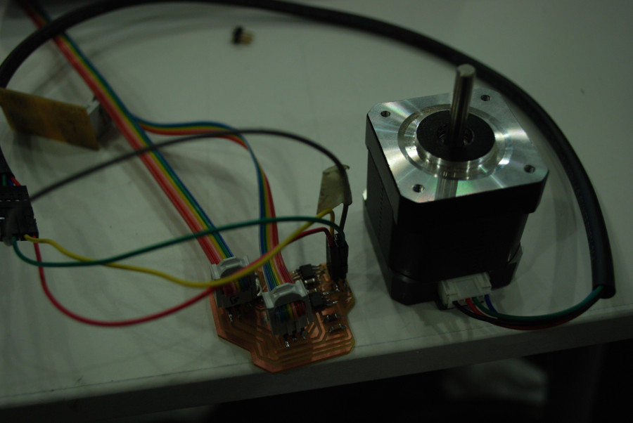
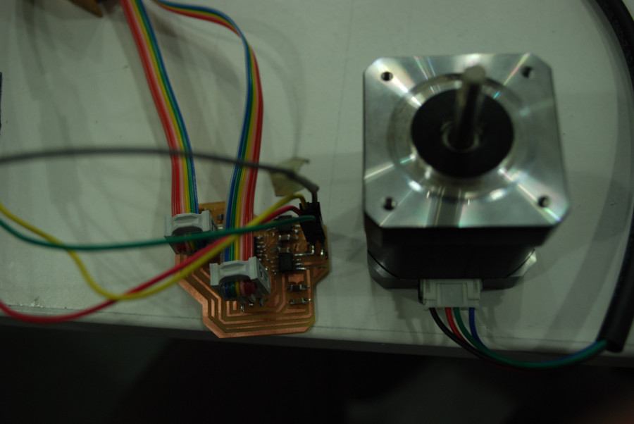
and looking at the cable connections of the Nema 17 I was able to figure out how to connect everything!
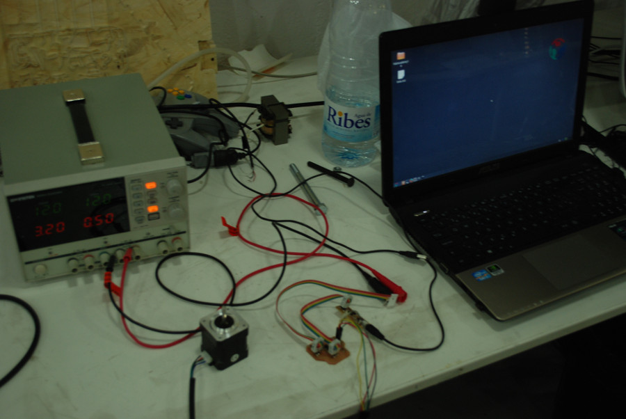
To be safe I only used a 9V voltage supply to the board so there would be no burns.