Computer-Controlled Cutting
Assignment:
1. Design, make & document a parametric press-fit construction kit.Design & first tests
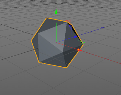
I do not have any background in laser cutting and parametric design. That's the reason I started with simple primitive shapes in C4D and using 123D Make to get an idea of how the shape is divided in different layers and how the hooks could work. I started with an icosahedron. As you can see the 123D Make extracted the shape. At this point I did not care about giving any width to the material neither to the fitting gapes. The very first try was with an .obj file and the result was awful.
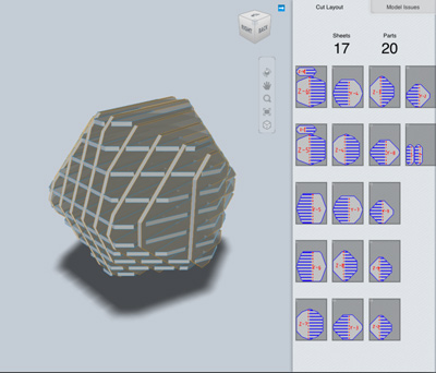
Then I decided to try with an .stl file and the result was much better all the gaps where perfectly generated.
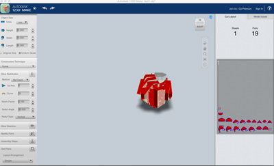
Easy peasy, so I decided to change a little bit the shape. I used the same icosahedron with beams and nodes. I dropped the .stl Without tweeking any values and the result was really disappointing. I made a clear idea of how this software works.
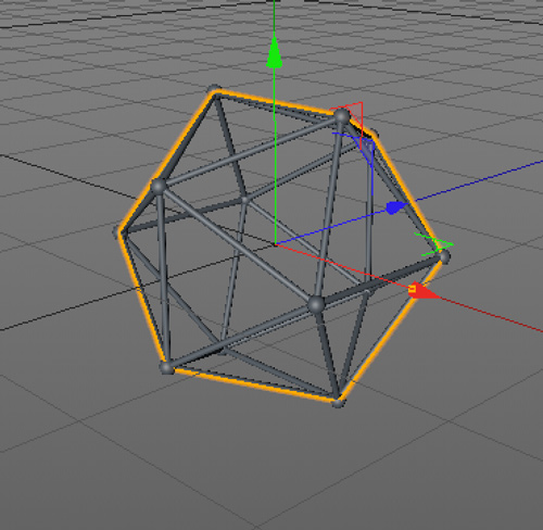
In order to continue this line of work I decided to change the the primitive shape: This one is with beams and nodes. The suppose the fail is caused by the lack of modelling the shape, since the beams and the nodes are rounded.I recovered one of my old projects and tried how would work with a highly detailed model
Again the software did something strange and too much tweeking was involved, besides I wanted to create samothing from scratch not recicling old projects.
Fail again, fail better!Now is time to experiment with some parametric design using Inkscape and cloned shapes.
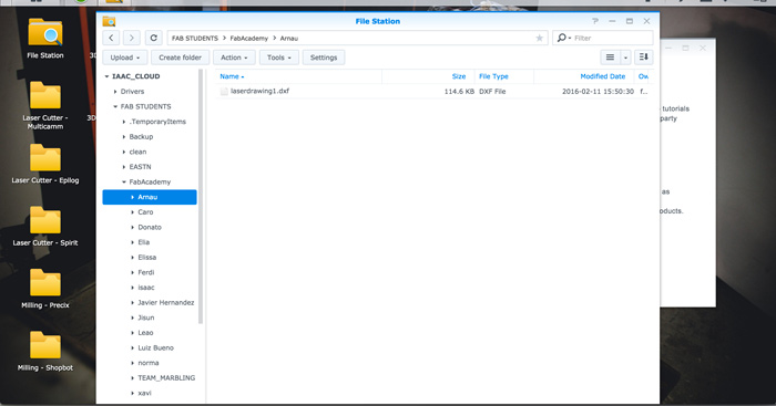
Some rectangles to know how the clones work, and uploading the to the Fab cloud for sending to the laser cutter.
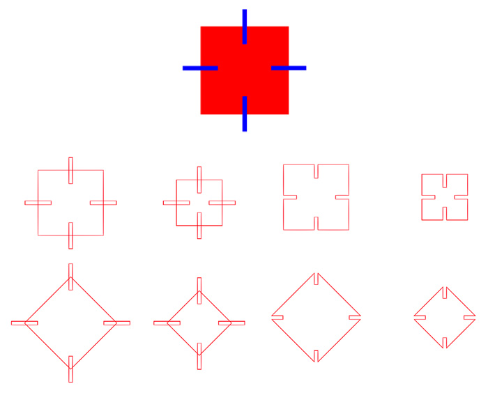
Here, I used shapes to create booleans between them, the numbers are a reference for knowing the distances. Finally, once I got the shape with the boolean holes I gave it the stroke line for laser cutting.The last step was uploading it to the FabLab cloud for send it to the laser machine.
I also wanted to try with Adobe Illustrator, I feel more confident with it, and I can design faster. The process I used was the same as with Inkscape: starting with color fill shapes, making booleans operations and converting the shpae to a path.
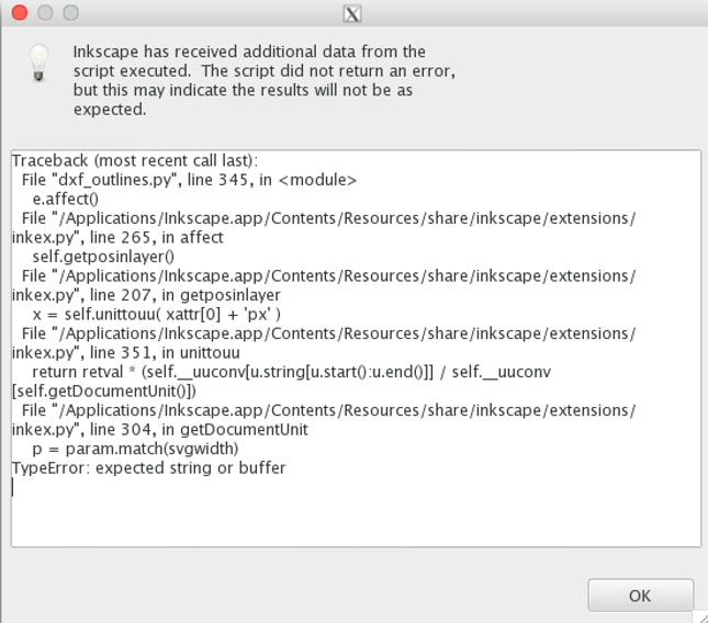
Because the laser cutting machine works with .dxf files, I exported the .ai to .svg for opening it in Inkscape and from there exporting the .dxf file.
Inkscape opened the .svg with an alert. This made me think that Illustrator and Inkscape don't manage the exporting process the same way.
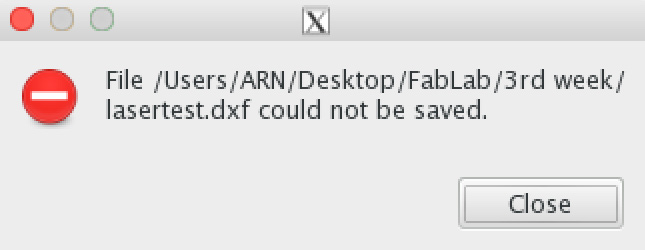
The problem came up at the exporting stage from the Inkscape.That's why I decided to export the .dxf file from the Illustrator and send it to the laser cutting machine.
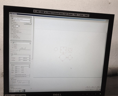
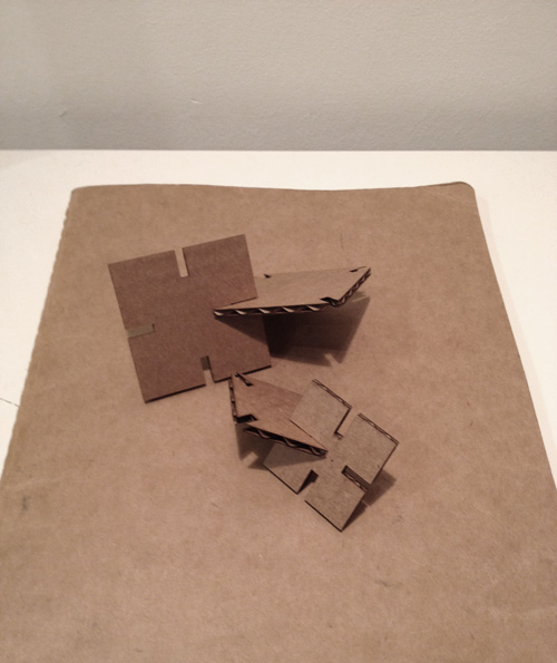
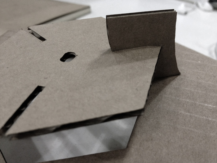
The next images demonstrate how is the process in the laser cutting machine. First we set the printing options in the .dxf file. Once it is set up and the cardboard is placed in the 0,0 point the laser starts the cutting process.Lastly, I've got my first cutting test. The fact of making the joints on both sides makes the pieces a little bit loose. Cutting one piece is enough. I need to keep improving!
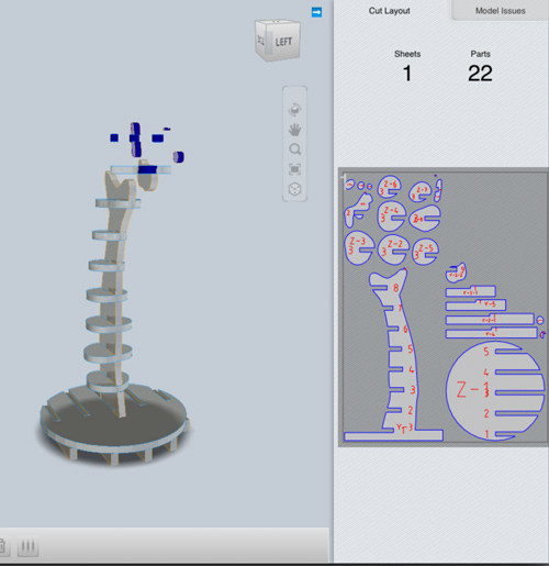
From now on I got an idea of what I would like to do for this week's assignment. I'm going to produce a cardboard lamp, usign the press fit kit techniques. The software I decided to use is Rhino I think it is a good way to practice and get more confident with this software. From curves to surfaces I started to sketch some shapes.
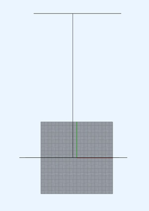
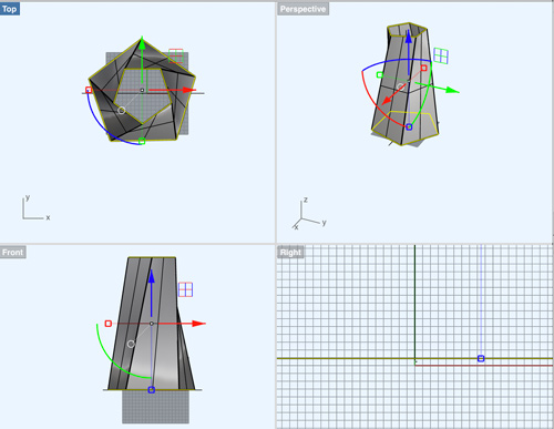
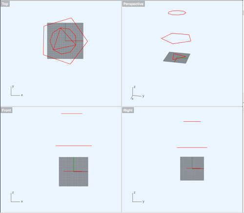
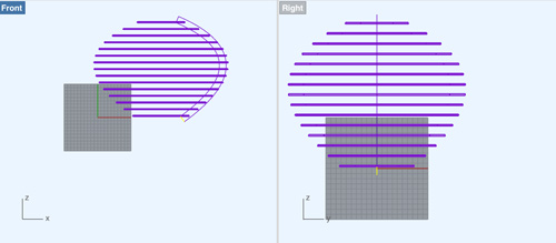
First working with the section profile and the top view to make the guides for the lamp size.The second step was to create a surface from the NURBS curves.
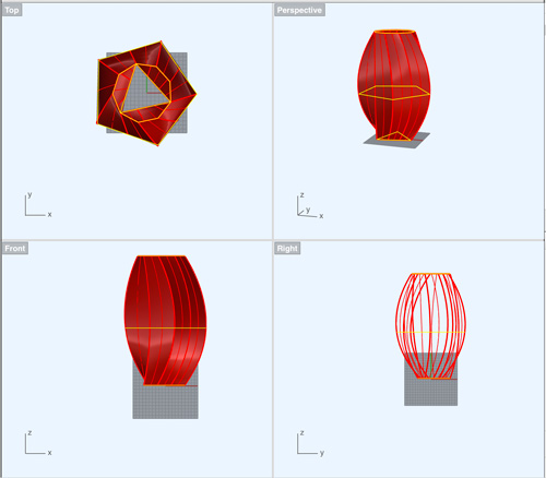
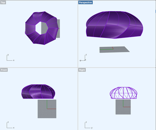
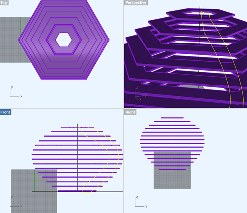
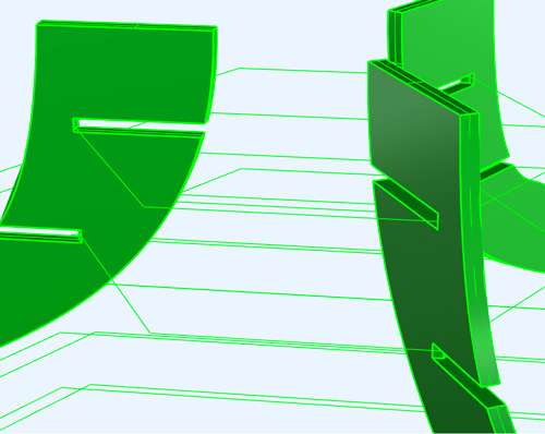
The next images show the modelling process. I decided the shape and I played with the NURBS and surface process.
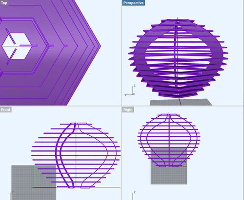
At the end, I made a boolean with the surfaces to create the press fit holes.
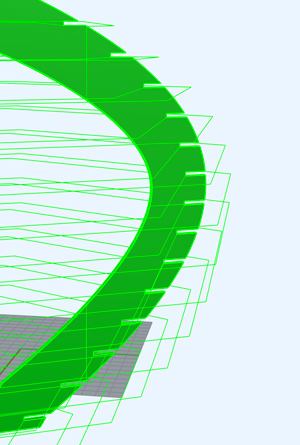
With a single joint it does not work. The structure is loose maybe, because we need to fix both axis. Moreover, I still need to reduce the gape distance.
Talking with Joao and Xavi, classmates from the FabAcademy, they encouraged me to make a doble joint to make the structure more rigid.
The document ready for printing. I exported a .dxf file for printing purposes. I will need some extra cardboard, because I have one shape that does not fit in 1000 mm x 1000 mm of cardboard. The setting I used for cutting were: Speed 20 / Power 60.
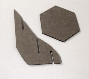
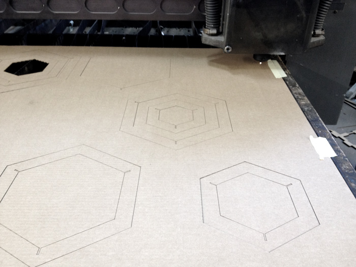
I decided to make the joint gapes smaller. I used 2 mm and 2.4 mm. With this gape reduction I ensure the cardboard will fit together and stay tight and rigid. Otherwise, the estructure was so baggy and sloppy. The next images are the last test befor printing the complete structure.
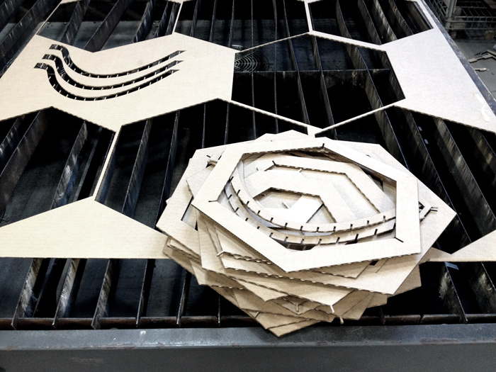
The laser cutting machine working on the final file.
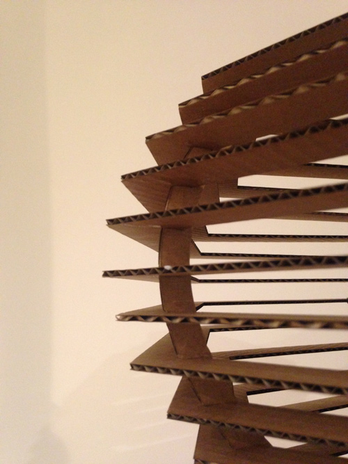
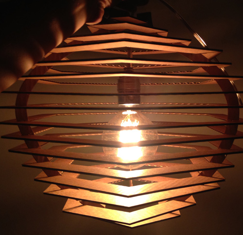
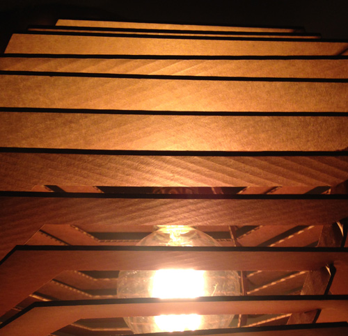
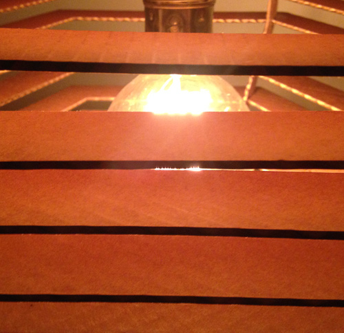
This is my press fit kit. Since the whole project has been done in Rhino I learnt a lot this week. I am a kind of rookie in Rhino. During the assembling process I faced some challenging problems. The structure was more difficult than I thought when assembling the different parts. I needed another pair of hands, even though I enjoyed this line of work and, during the next weeks, I want to keep improving different designs for cardboard lamps.
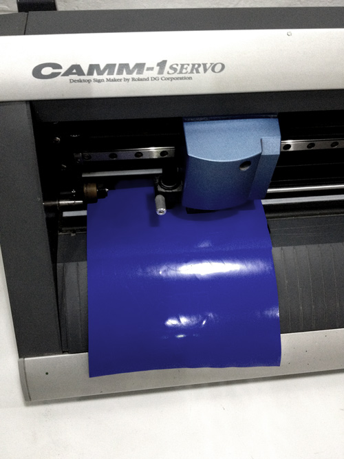
Once the lamp was finished, I printed some vinyl just for fun. I tried to make a doble contour line, but at the end I messed up, so I just used the fill. The vinyl cutting machine is a Roland Camm-1 Servo. I designed the artwork in Illustrator and from Windows OS, usign the Roland drivers. First I mesured the sheet of paper and once I've got the papae rsize I designed the artwork, and then export the .svg and printing. After my test, Ferdi (our instructor) installed the Raspberry Pi to control the Roland Camm-1 Servo vinyl cutter. And I'm willing to print throught the Raspberry Pi interface and print from the Raspberry Pi terminal. ;)
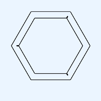
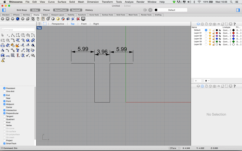
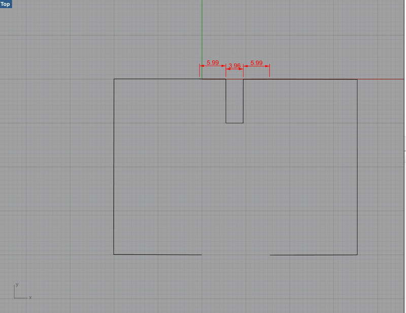
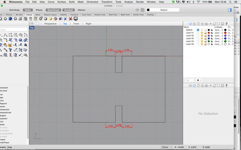
Beacuse I had some time I tried a simple exercise with Rhino and parametric design (no Grasshopper involved). You create a file. And design your joints with Polyline command.
Then you use the Dim command to view the distance values.
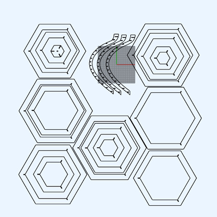
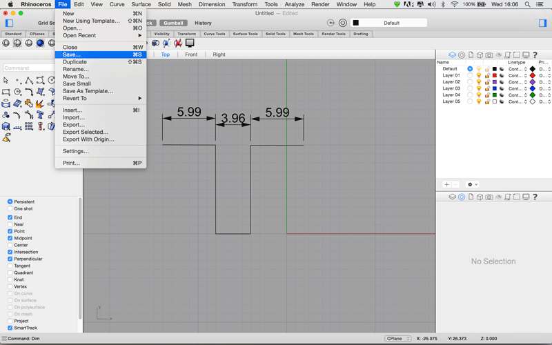
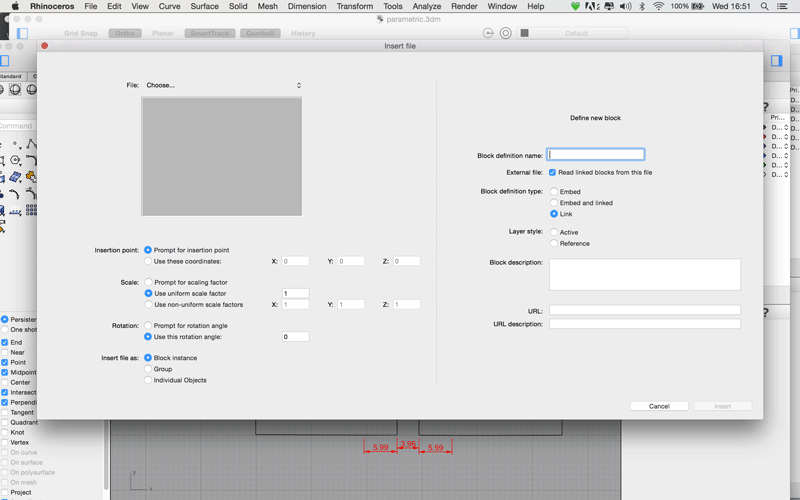
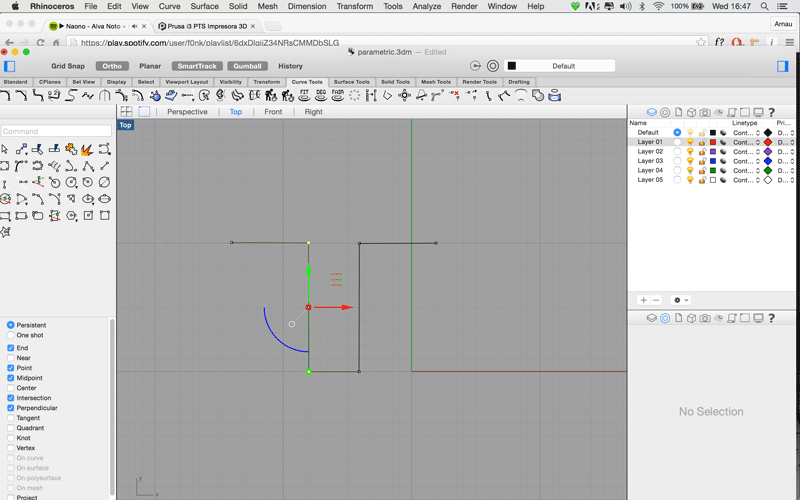
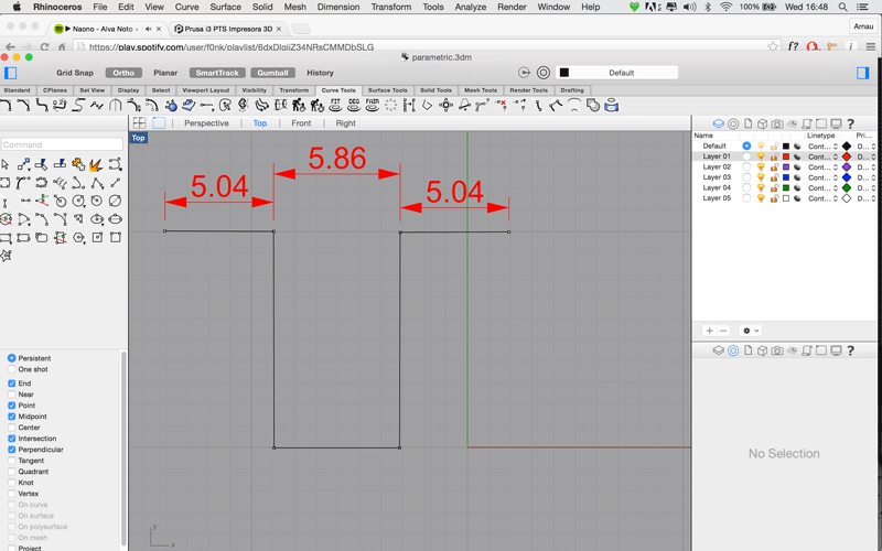
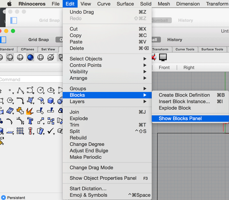
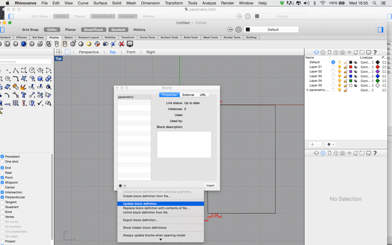
Save it as Rhino fileCreate a New file, the actual design you want to do with joints.Go to File > Insert file, choose the file, make sure the Link option is checked.Place the joints where you want them to be.Go to the first file and modify the control points.Use the Dim command again for the new mesures.Save the file and go back to the final file shape.Navigate to the menu: Edit > Blocks > Show Blocks PanelA window pops up.Select update block definition.Boom! Your joints have been updated.Download the files here