Week 4: Electronics Production
Mill, Solder & Program an In Circuit Programmer
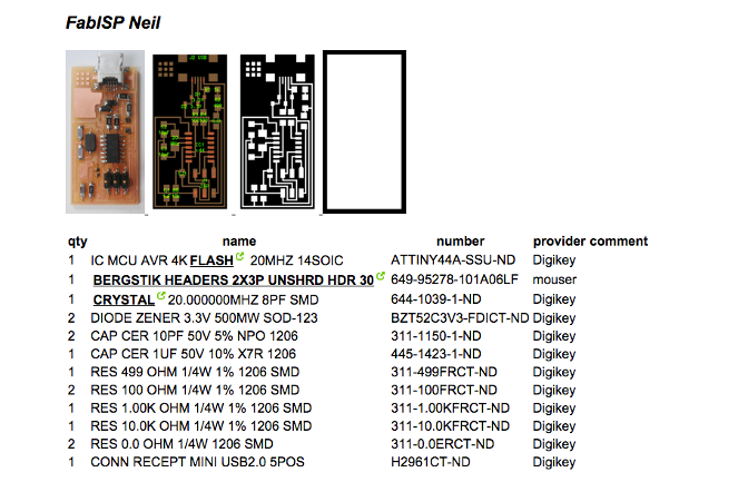
This week we made the FabISB Niel circuit board.
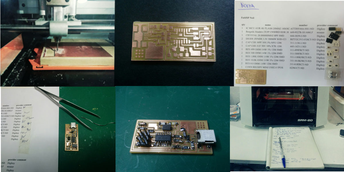
Introduction Milling Machine Roland SRM-2D
Ferdi´s introduction to the Roland SRM2D milling machine. Two ways to make a PCP (printed circuit board), FA1 or FA4. The difference is the choice in materials. FA1 might be a bit "old school" we prefer it as FA4 utilises glass fiber, which is nasty to mill. Roland SRM 2D milling machine takes away the parts of the cupper board we don´t need. The left-overs are conductive traces to which we later connect the components. (To safe milling time, there can be cupper "islands" on the board, which are not connected, so don´t do anything).
The workflow starts with loading the b/w image of the traces into the software, select the correct milling machine, and specifiy the process settings. After origin is set, the first test cut sets with 0 cut depth to check if everything is positioned straight. First milling strategy is the "engraving" of the cupper traces, done with a milling bit size 1.64. In process the cut depth is 0,1; 4 offsets (= rounds of milling). In output, xyz are set to 0. After the milling of the traces, load the "cutting" image and exchange milling bit, size 1,32. Cut depth now sets to 0,5; stock thickness is 1,5; number of offsets is 1. Output stays same (xyz = 0). I was very happy with the result of the shiny cupper board.
Assembling the Components
I have never done any smoldering, but was looking forward to what appeared to be a calm and meditative practice. This tutorial helped. The information sheet specifies all components needed. Sticking them next to their description helps, starting from the middle of the board, working towards the edges. Enjoyed the work, but always seemed to miss a third hand to handle the heat pen, the wire, the tiny board and the miniscule components. Tried to leave the smoldered surfaces "smooth and shiny". However, I worried a few times that I actually burned the components. While the result might not be the prettiest circuit board around, I enjoyed the soldering and the board works.
Programming the FabISB
Next I downloaded the firmware.zip and the crosspack for AVR development to program the board. Open terminal and go to location of the fabISP_mac.0.8.2_firmware. Command to check location in terminal is ls, command to move the folder hierarchy up/down is cd. Next I ran the prescribed commands "make clean" and "make hex". The latter didn´t work. I got the multi-meter to check the connections between the components on the circuit board. I found a connection between C2 and VCC that shouldn´t be there. I desoldered the problematic spot, connected the programmer ran "make clean" connected to USB port, ran "make hex", "make fuse", "make program". Done.
Next I desoldered SJ1 and SJ2 (with the help of the tweezer, carefully, not to rip the traces off of the board). Next, connecting circuit board to USB laptop, click on Apple --> about this mac --> open: system report --> open USB. Didn´t show the FabISB - which it should : (
Next: "beeping" through all connections to control if something is wrongly dis/connected. Everything seems fine. Resoldered some "ugly bits". Still nothing. -- So, we rechecked everything again: solerding, beeping, reprograming. It works fine, until I ask laptop to recognise the FAB. Nope. I tried a working board from another student, which my laptop recognised. : /