Week.08 Embedded Programming
Pin Descriptions from ATtiny24/44/84 DataSheet
Here below what I learned by reading the datasheet
VCC
Supply voltage.
GND
Ground
Port A (PA7...PA0)
Port A is a 8-bit bi-directional I/O port with internal pull-up resistors (selected for each bit). The
Port A output buffers have symmetrical drive characteristics with both high sink and source
capability. As inputs, Port A pins that are externally pulled low will source current if the pull-up
resistors are activated. The Port A pins are tri-stated when a reset condition becomes active,
even if the clock is not running.
Port A has an alternate functions as analog inputs for the ADC, analog comparator,
timer/counter, SPI and pin change interrupt as described in ”Alternate Port Functions” on page
Port B (PB3...PB0)
Port B is a 4-bit bi-directional I/O port with internal pull-up resistors (selected for each bit). The
Port B output buffers have symmetrical drive characteristics with both high sink and source
capability except PB3 which has the RESET capability. To use pin PB3 as an I/O pin, instead of
RESET pin, program (‘0’) RSTDISBL fuse. As inputs, Port B pins that are externally pulled low
will source current if the pull-up resistors are activated. The Port B pins are tri-stated when a
reset condition becomes active, even if the clock is not running.
Port Balso serves the functions of various special features of the ATtiny24/44/84 as listed on
Section 12.3 ”Alternate Port Functions” on page 61.
RESET
Reset input. A low level on this pin for longer than the minimum pulse length will generate a
reset, even if the clock is not running. The minimum pulse length is given in Table 22-3 on page
183. Shorter pulses are not guaranteed to generate a reset.
ATTiny 44 - Arduino pin
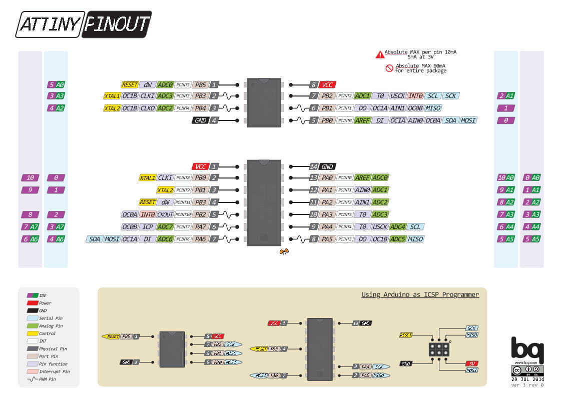 Here the pin equivalence from ATTiny 44 and the Arduino Pin
ATTINY LEGS AS ANALOG INPUT:
Leg 6 (Arduino pin 7)
Leg 7 (Arduino pin 6)
Leg 8 (Arduino pin 5)
Leg 9 (Arduino pin 4)
Leg 10 (Arduino pin 3)
Leg 11 (Arduino pin 2)
Leg 12 (Arduino pin 1)
Leg 13 (Arduino pin 0)

ATTINY LEGS AS PWM (ANALOG OUTPUT):
Leg 8 (Arduino pin 5)
Leg 7 (Arduino pin 6)
Leg 6 (Arduino pin 7)
Leg 5 (Arduino pin 8)

ATTINY LEGS AS DIGITAL INPUT/OUTPUT:
Leg 2 (Arduino pin 10)
Leg 3 (Arduino pin 9)
Leg 5 (Arduino pin 8)
Program board to do something
Installing Arduino IDE
For my assignment I used Arduino 1.6.8 and I'm using a Windows 10 First step install Arduino from the official web page.
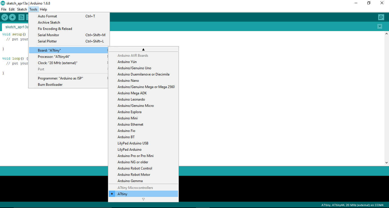
Installing ATtiny support in Arduino
Source Arduino LibraryDownload the Arduino's library Go to your Arduino folder in windows/user/...Documents/Arduino ) Create a new sub-folder called "hardware" Create a new sub-folder "avr". (../Documents/Arduino/hardware/avr) Paste the unzipped files that you downloaded. Open Arduino Go to "Tools" --> "Board" You should see now a list of Arduino boards, including ATtiny
USBtinyISP driver
I also have to isntall the USBtinyISP driver for Windows 10.
Seems the driver are not available but I have found the driver for Windows 7 in the Adafruit web page and it works!
Source Drivers USBtinyISP driver v1.12here the direct download to the driver
Windows USBtinyISP signed driver built with libusb v1.12 from AdaFruit web site

The operation of Burn Bootloader allow programme the MCU.
Burn Bootloader
Open tool menu
select Board ATtiny
select processor 44 or 45 or Atmega(Leonardo)
Clock 8Mhz Internal for ATtiny 45
Clock 20Mhz External for ATtiny 44
Port: COM x
Preogrammer USBtinyISP

then Burn Bootloader
Let's go to write and upload a simple code and see what happened, but forst of all I need to compare the Arduino Pin with the Attiny 44 pin. The pin have a different number!
The Led Button Code
Whit the Arduino IDE I decide to try my board using a simple code for led button. When I push a button led turn on! After the comparison of the pin from Arduino and Attiny I have to define the pin n 3 as a button pin and the pin n 7 for led pin.

Source Code Button_ATTINY44.ino
Button_ATTINY44.ino
// Led Button for TTiny 44 -  Fab Academy 2016 - Elia De Tomasi

const int buttonPin = 3;
const int ledPin =  7;

int buttonState = 0;
void setup() {
 pinMode(ledPin, OUTPUT);
 pinMode(buttonPin, INPUT);
}
void loop() {
buttonState = digitalRead(buttonPin);
if (buttonState == HIGH) {
digitalWrite(ledPin, HIGH);
  } else {
   digitalWrite(ledPin, LOW);
  }
}

 Source Eagle Files
Hello LED Button.brd
Hello LED Button.sch
Arduino Class
Guillem
Input output - LDR e Servo
During the Fab Academy here at Fablab BCN we also have meet Guillem Camprodon
.Guillem have taught the firs basical knowledge of Arduino IDE and tested some sketch code in the library.
Here you can find is own presentation
After the presentation of Guillem we also have recived the first pratical knolwdeg of Arduino by oru tutor Ferdi. Here following there is a video showing a siple analog input as smartphone led light and a output like a servo motor that rotate
Copyright © Elia De Tomasi 2016