Week 05 - 3D Printing and Scanning
Assignment:
- test the design rules for your printer(s) (group project)
- design and 3D print an object (small, few cm) that could not be made subtractively
- 3D scan an object (and optionally print it)
- Extra Credit: Make your own scanner
- This week’s home work page
Testing the design rules for our 3D printer(s):-For our group task, we had a detailed introduction to Cura, an open source software that prepares your model(s) to 3D printing.
We covered terminology and what each tool does in Advanced mode and Expert config of Cura, in order to have control in how to control your 3D printer to best print your file.
We covered topics like:
Temperature;
Brim;
Raft
Support;
Materials;
Retraction;
Skirt;
Cooling;
Plugins;
Thickness of lines, layers, infill, top and bottom, ...
And much more

-With this learned, we are all using similar settings to our printings, depending on the type of object designed by each.
In my case, having in mind how a 3D printer works, I designed my object already having in mind that my object should stick to the platform. For this reason, my base is a large disk and from this, on to a smaller body.
Printing with a simple fdm 3D printer using PLA, no heating bed. For a better stick, 3D printing spray (Hair spray) was sprayed onto the platform.
I used 0.2 mm as layer height, 20% fill density, 0.8 mm as bottom and top thickness, print speed 50mm/s and no Brim or Raft or Support.
This is our group's page, please click here.
3D Printing: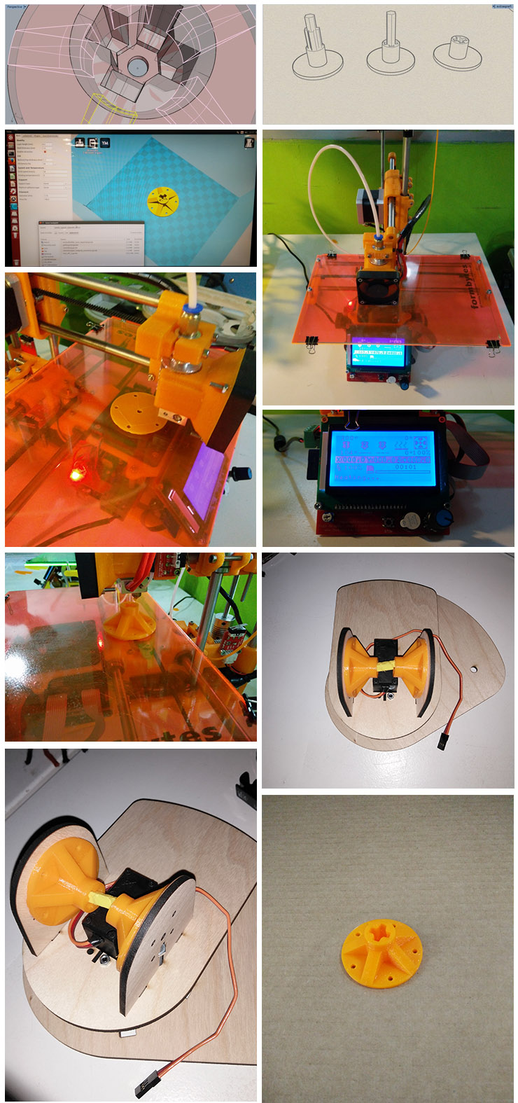
-This model I designed would not be able to be produced in a Lathe, neither in a normal Milling Machine. It does not require a lot of structural strengh so the 3D printer was ideal for this task. It weights 7 grams and it took 40 minutes to be printed.
The center of its axis will receive a nut and after that, a laser cutted wooden part to serve as spacer. As I mentioned before, combining a laser cutter with a 3D printer plus creativity, that allows one to produce almost any structural part. If you have a milling machine, even better.
Center Spacer Ulearn02 by Luiz H H Bueno on Sketchfab
3D Scanning:It maps the object by driving a needle-like sensor that senses when it touches the part. Combining all those points together with the path it took, it creates a file that we can export as STL in the same software.
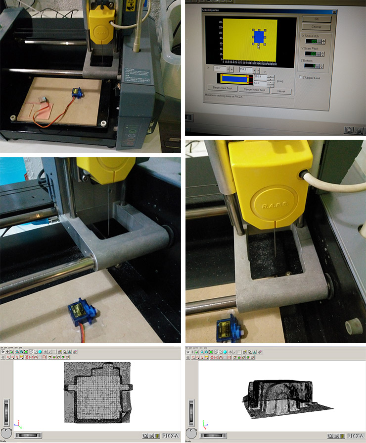
-From this technique, it inspired me to extract the points generated by the robotic arm and to combine them to also create an 3D volume. I'm starting this process and by the end of my project I intend to implement it, having an arm that knows where an object is on its cordinate area, leaving room for interaction. If you look at the 3D printed model I developed in this task, this is a spacer for the base of the 1st part of the robotic arm.
-Download my files:
-3D print model - STL file
-3D scanned STL file
Back to top