Electronic design
Task: | redraw the echo hello-world board,
add a button and LED (with current-limiting resistor)
check the design rules, and make it
This week was about learning graphical layout editors such as Eagle . The following tutorials were extremely helpful to understand how to create schematics and design layout with the program:
1. Fab Academy English tutorial
2. Jeremy Blum tutorial
The first thing you do in Eagle is add your components (type "add"). The fab inventory is listed on this Library. Make sure all libraries are highlighted with a green dot- otherwise they wont appear in the list of components. Always choose the "1206 components" as this is what you find in Digikey.
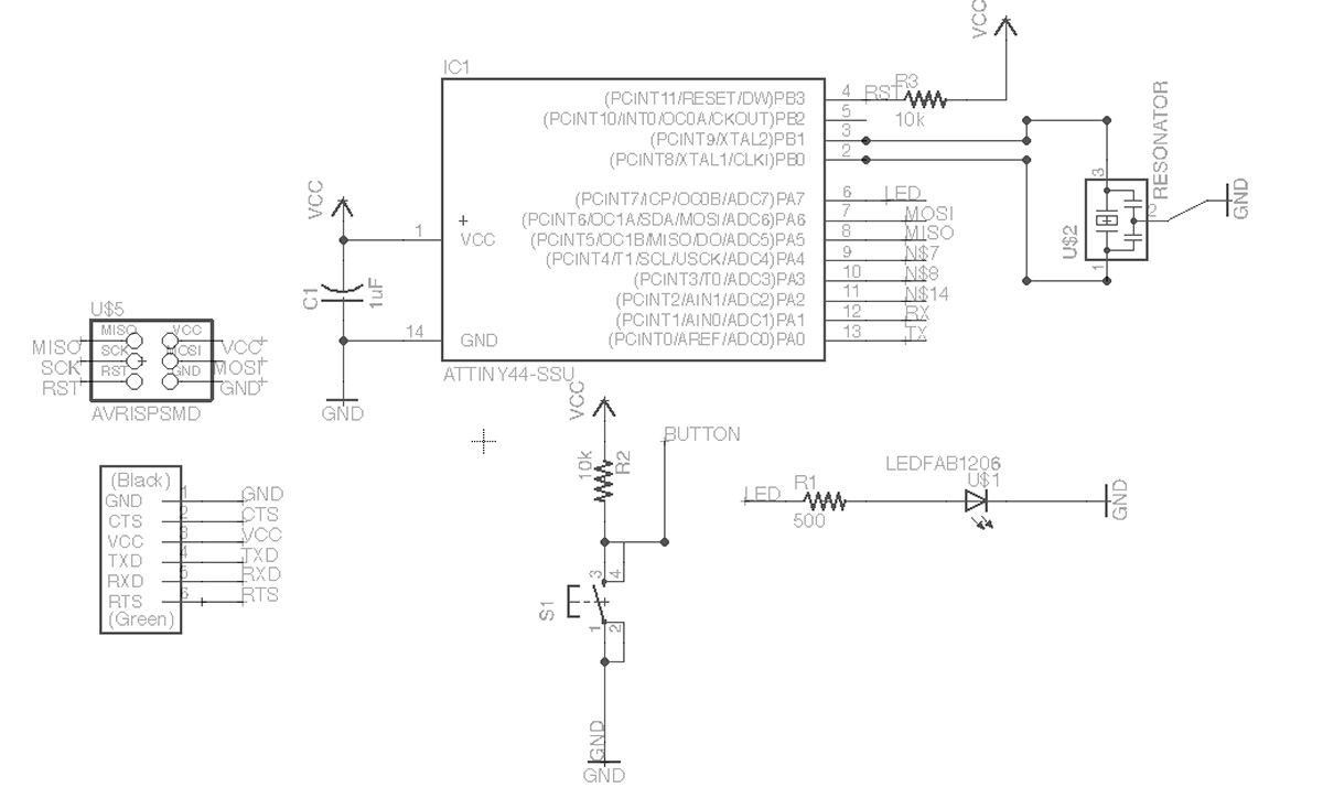
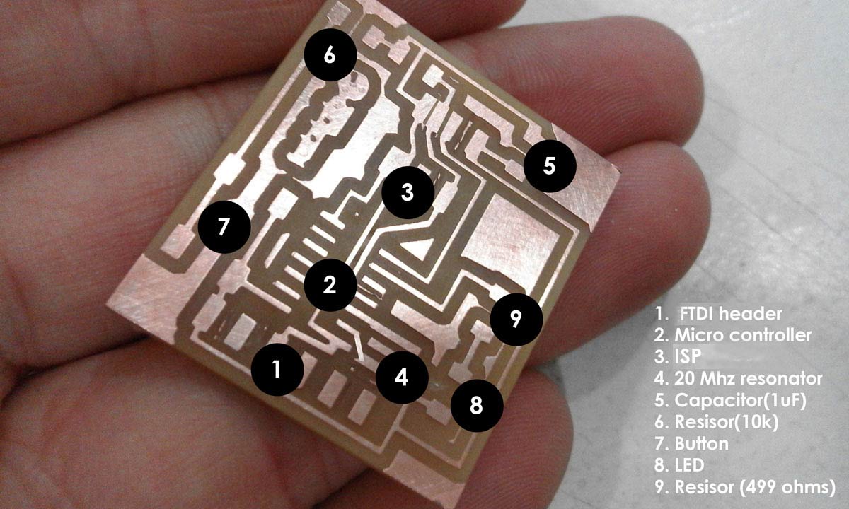
As you can see pin 10 was use to connect the button via the micro controller and pin 6 for the LED (check ATTINY pin outputs). The resistor required was calculated using the specification of the LED from digikey and LED calculator. At this point it is extemely important that everything is properly connected and named. Use junction points for all corners.
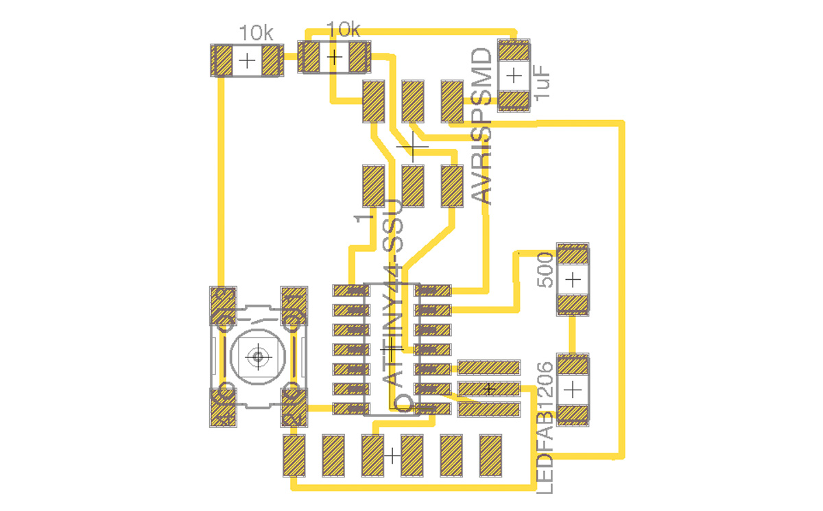
Once the schematic is done and checked. Layout for design is next- this can be automated or manual. You can use the bottom of components as routes for shortcuts but always double check with DRC command using 16mil spacing. One of my junctions connecting the resonator to pin 3 wasnt properly connected in the schematic; therefore eagle did not inform me at this stage but luckily i was able to correct it while soldering and the connections happened to be right near each other.
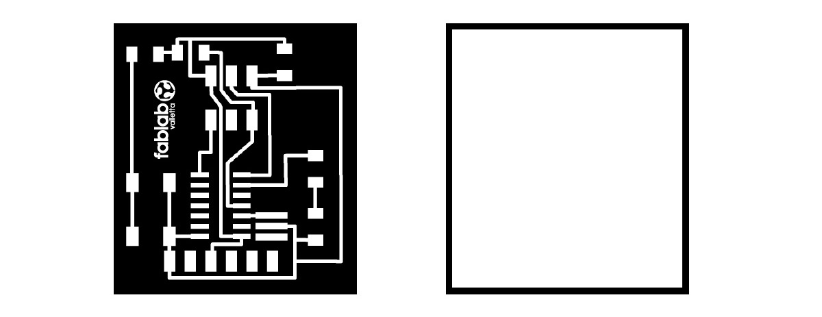
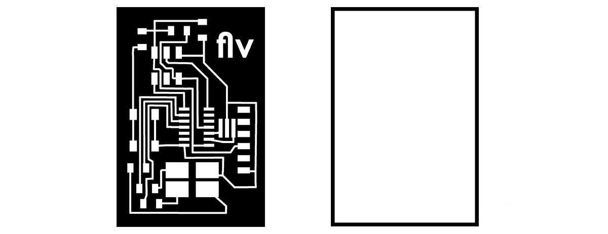
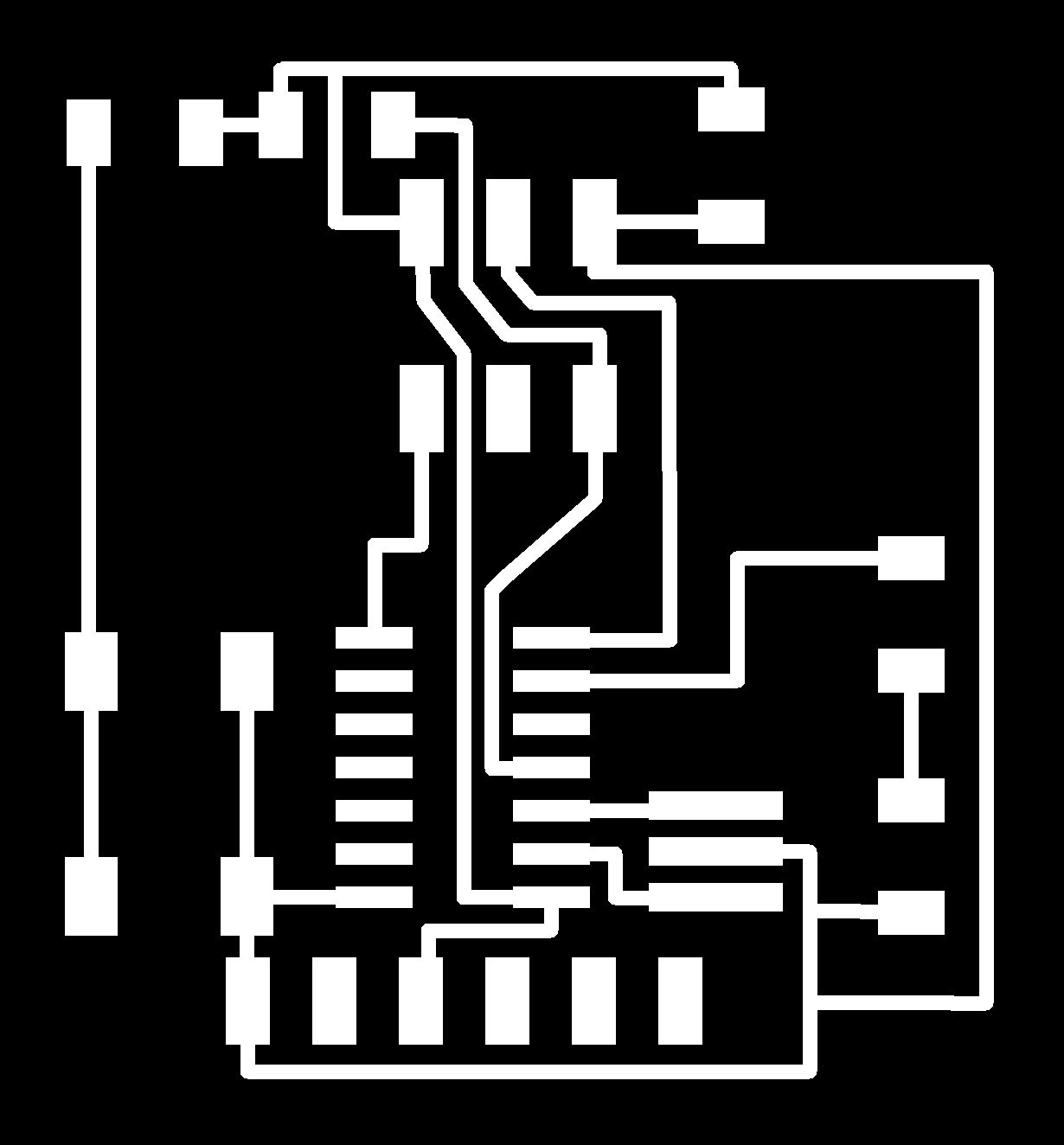
Once layers were cleared a BLACK AND WHITE image needs to be saved for etching and cutting. The border was done in gimp by enlarging canvis size by 1.6mm (the size of the larger bit- if less you can get errors and ruin the etched board). If the image is not black and white or saved with a resolution of at least 1k pixels- circuits may merge- this unfortunately happened to me and had to be corrected manually. The milling machine cuts black using Fabmodules
Check Week 6 for more details on setting up fab modules
(above is another eagle file I worked on this week to add rgb lights)
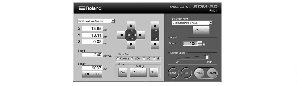
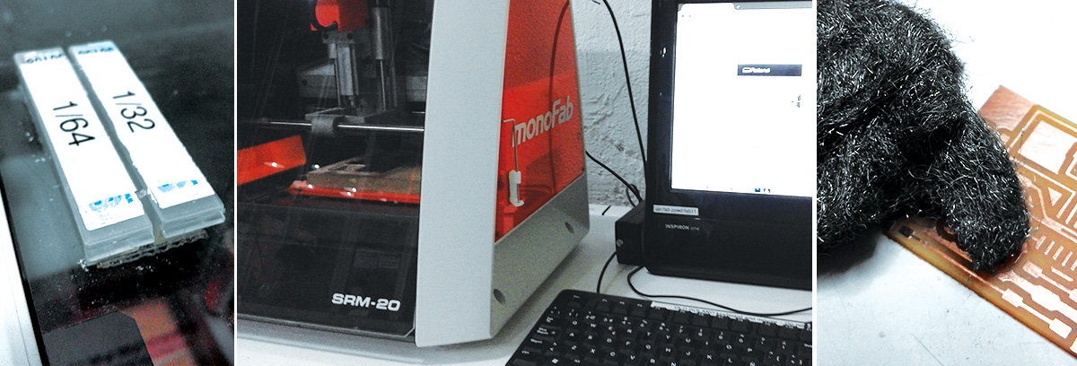
Upload png; Choose milling machine; Choose 1/64 bit for etching/ 1/32 for cutting; make all outputs zero; Offsets 4 for etching/ one for cutting; change cut depth; diameter. (always study cut path to make sure it looks correct)
|Etch
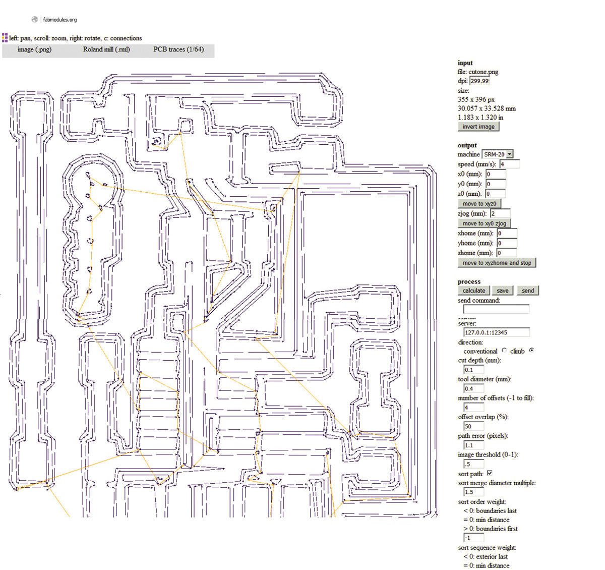
milling file
png
|Cut
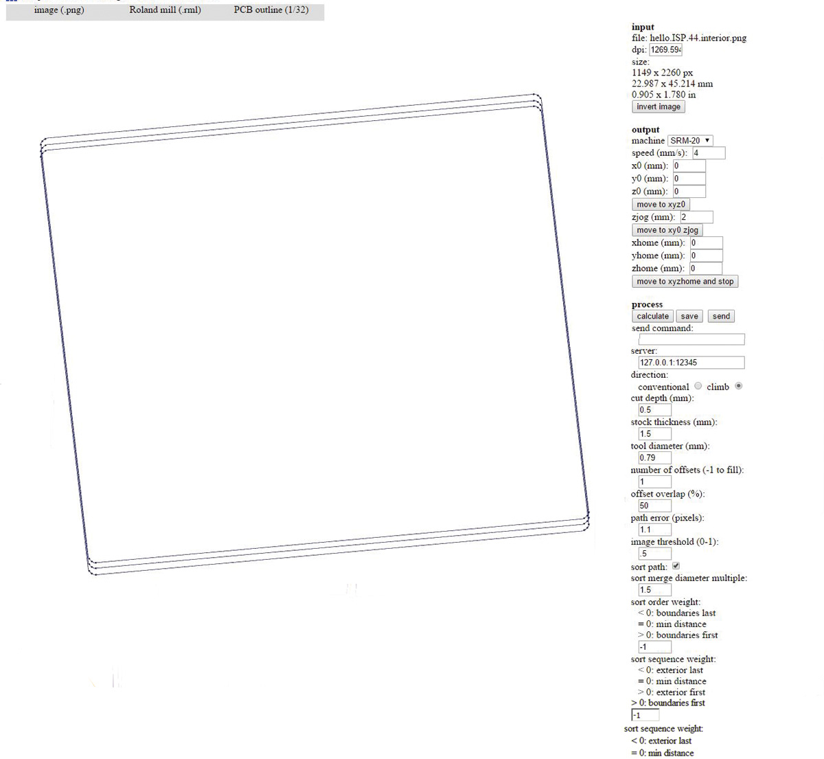
milling file
png
|Roland interface- set x/y and z axis; press 'cut' to upload .rml gcodes.Change milling bit according to rml file. Make sure circuit board is straight and flat on bed. One error i encountered was that when placing the bit too high up in the srm-20, the z milling was drawing in air. Use steel wool to clean circuit board.
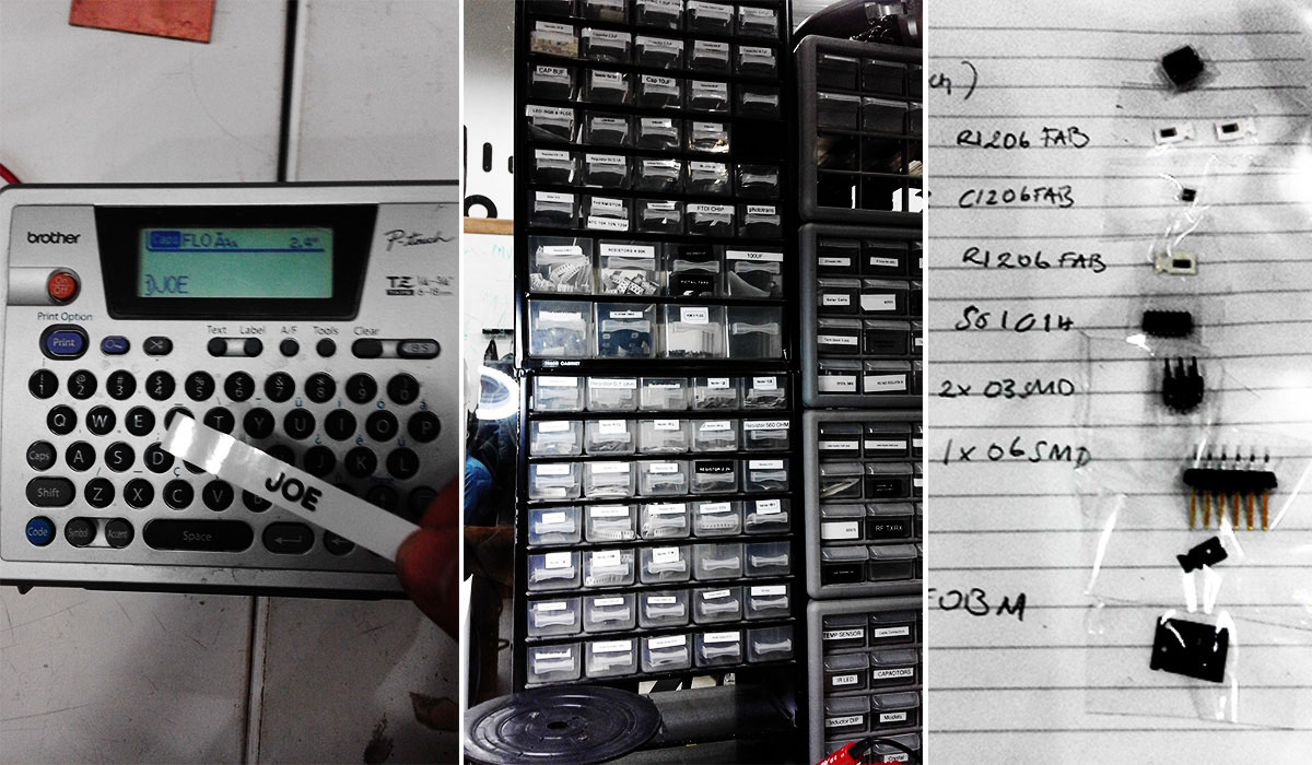
| Generate eagle text file to find components. Fab lab BCN have a good tagging systems thats to this tagging printer.
"run bom" command in eagle to obtain item list.
| Soldering. (refer to week four)
|Download this weeks files .
|Brief MIT
|Lecture Neil Gershelfeld