Output devices
Task: | add an output device to a microcontroller board you've designed and program it to do something
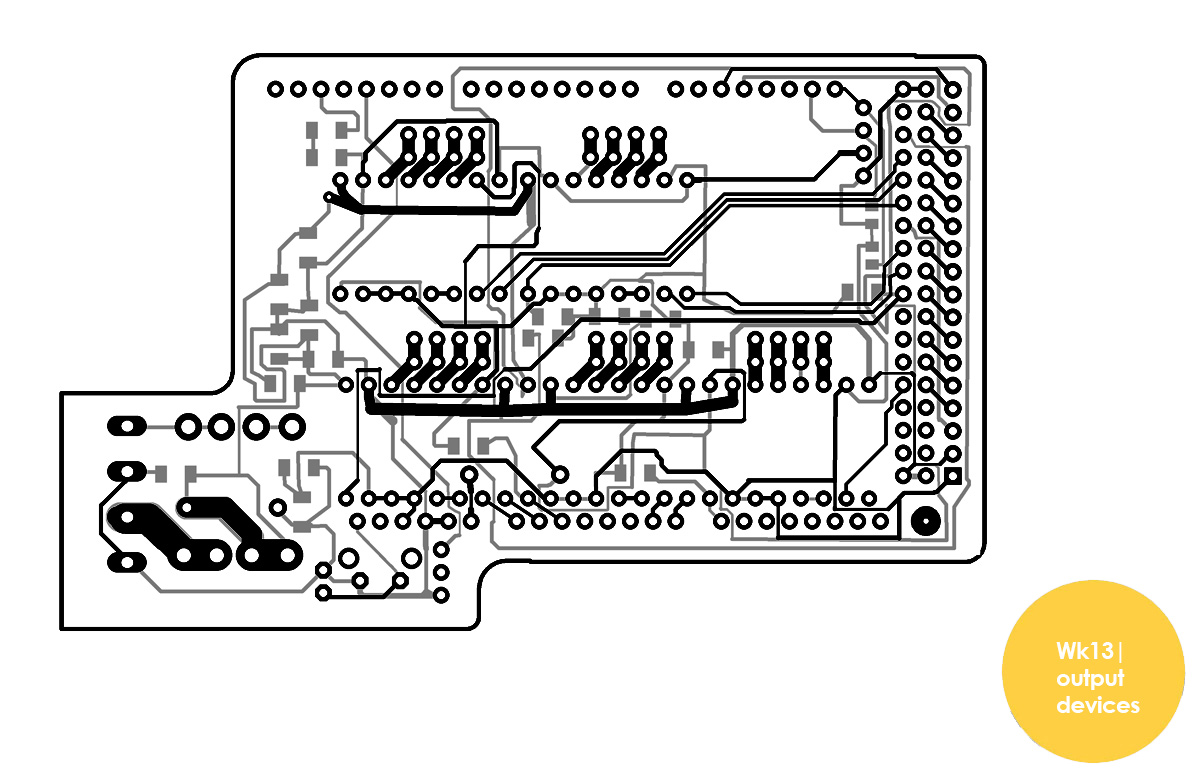
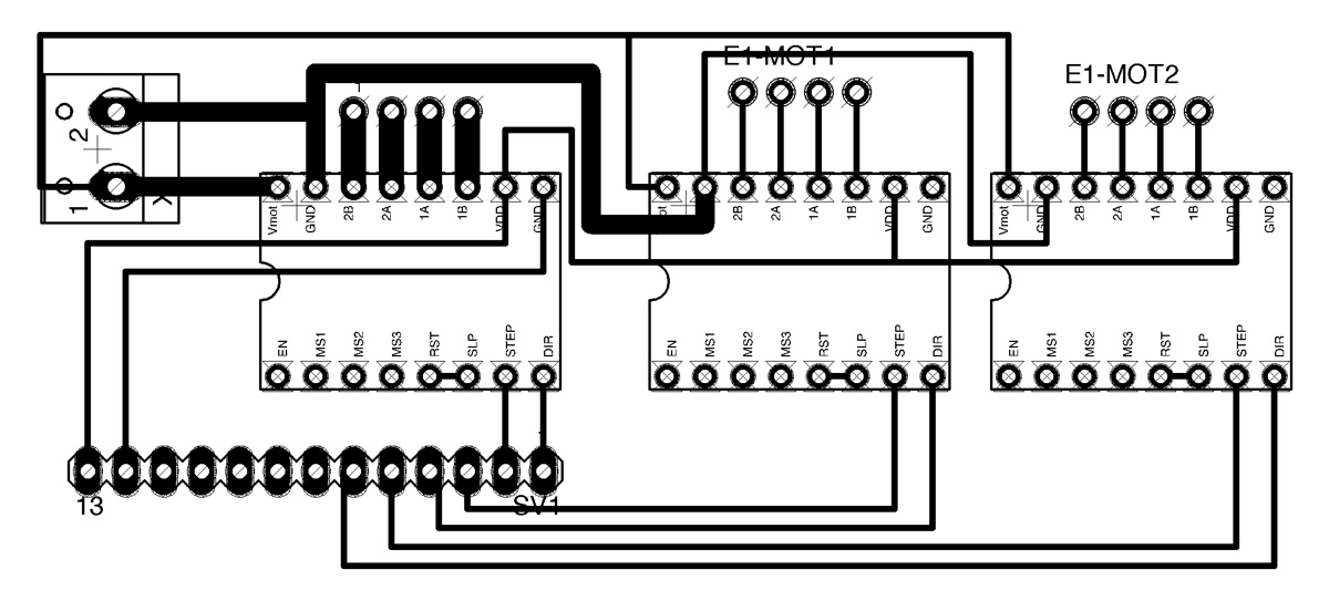
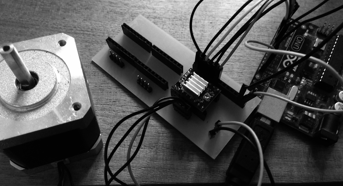
This week i wanted to work on a shield which would attach to an arduino and perform multiple outputs. To do this i modified the open-source ramps board (Watch this review to understand better) I want to use this system as a hack on a reprap 3d printer for my final project. Therefore I modified the ramps board to suite my needs; at this point in time to a three stepper motoros so that i could properly understand what is going on. ( i was ready to mill the pcb board shown in the header which is a version including auxiliary for LCD; a servo motor; 5 stepper motors but this got too complicated and if something went wrong it would be almost impossible to find out)
I also wanted to understand how to mill on two sides of the board. However, because i simplified the board and managed to fit three stepper drivers on one side with a 16mil bit; i only used holes so that i could create containers as a shield. This shield would be the basis of my development to a final modified Ramps board.
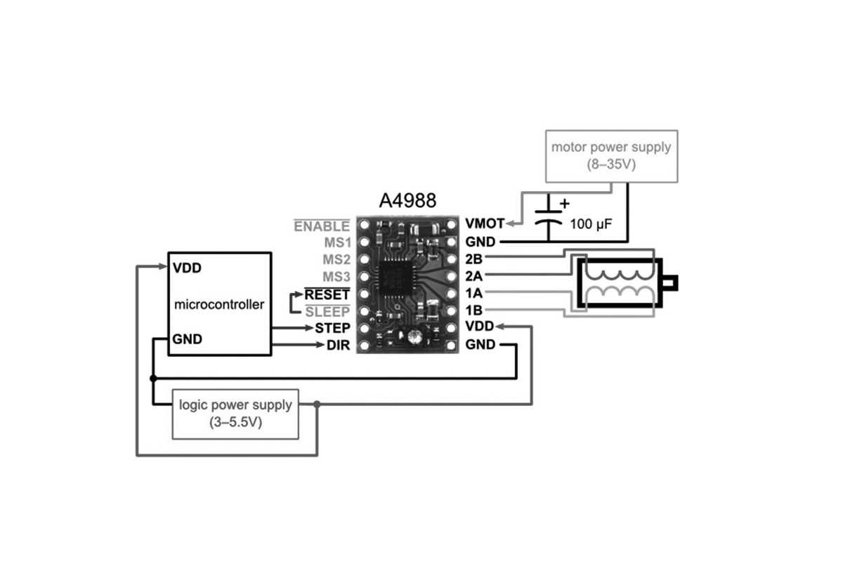
This board was also designed on the basis of understanding how pololu drivers work.
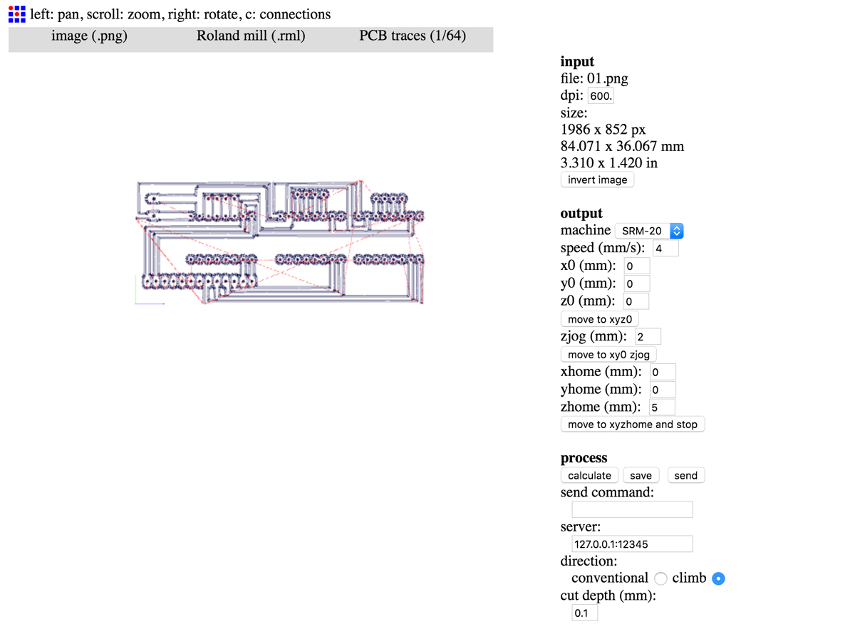
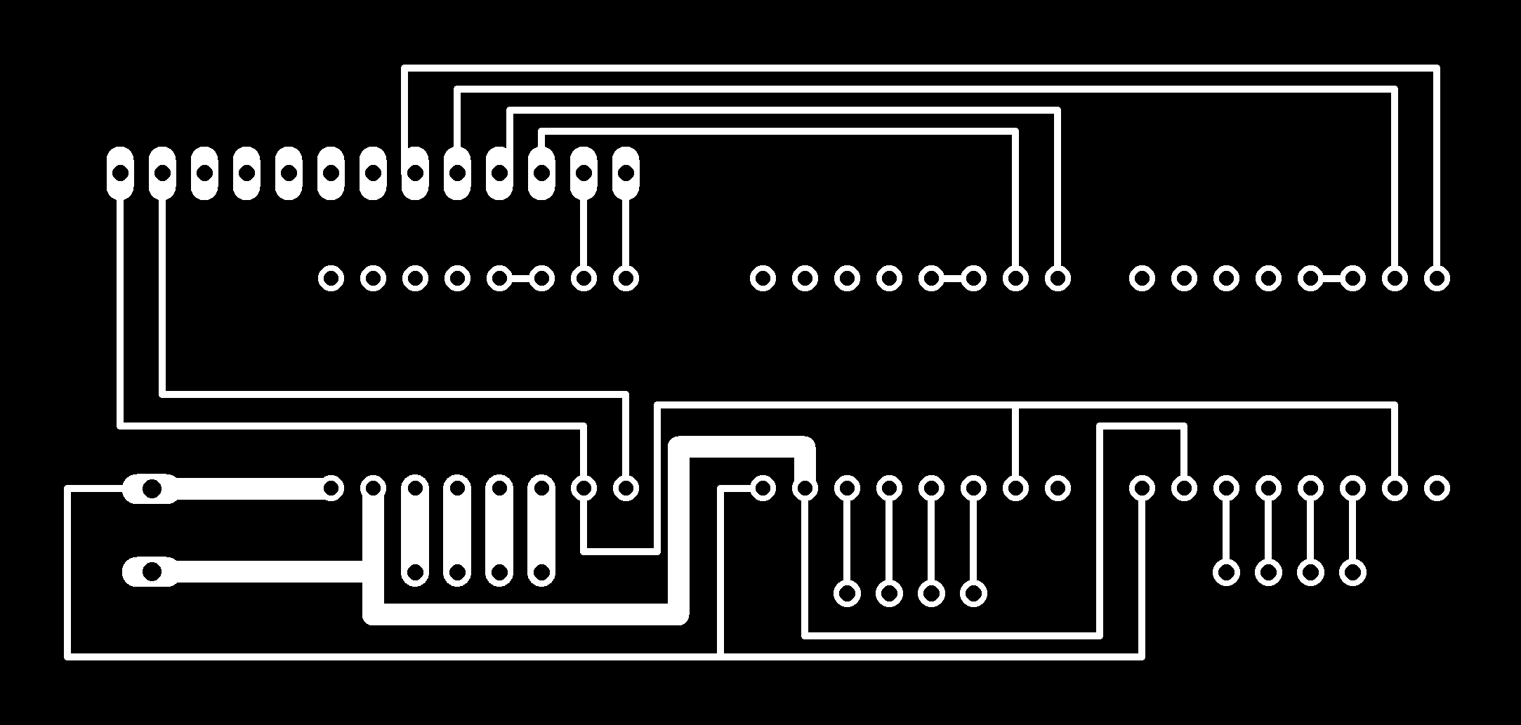
inner trace png
inner trace milling file
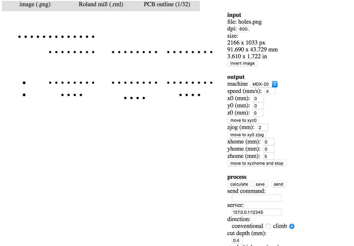
holes need to be cut with the 64 bit acting as a 32 bit cut.
holes png
holes milling file
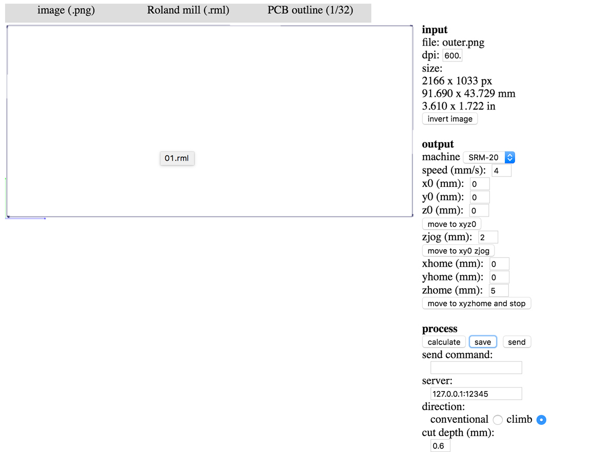
outline png
outline milling file
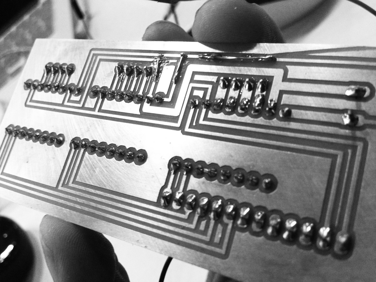
On the last hole... the mill also decided to go crazy and lash through the end of my board. So inorder to save time i created connections using wire.
When using the stepper motors to move the perisaltic pumps. I needed to increase the voltage of the drivers to 1.2v. This is done by rotating the screw on the driver and reading volage between the screw and ground.
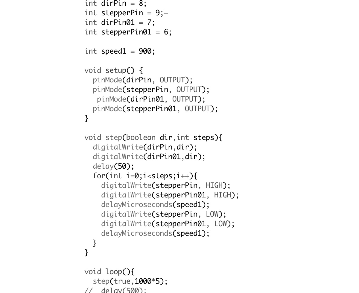
Gif showing two motors working using code attached.
This was continued a stepper expander for the
final project
|Download
|Brief MIT
|Lecture Neil Gershelfeld