hola soy un mensaje secreto wiwiwi wawawa
EMBEDDED PROGRAMMING
Assignment:
| | | | | | | | | | | | | | | | | | | | | | | | | | | | | | | | | | | | | | | | | | | | | | | | | | | | | | | | | | | | | | | | | | | | | | | | | | | | | | | | | | | | | | | | | | | | | | | | | | | | | | | | | | | | | | | | | | | | | | | | | | | | | | | | | | | | | | | | |
// CONCEPTS AND INFORMATION TO KNOW BEFORE YOU START:
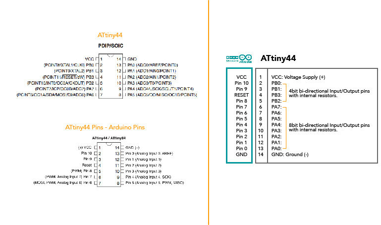
While I was reading almost all of the ATtiny 44 datasheet, I had to look for a lot of concepts about electronics. This are some of which I think are some of the most important ones:
To understand about pins of the ATtiny talking "Arduino" I made this diagram.
| | | | | | | | | | | | | | | | | | | | | | | | | | | | | | | | | | | | | | | | | | | | | | | | | | | | | | | | | | | | | | | | | | | | | | | | | | | | | | | | | | | | | | | | | | | | | | | | | | | | | | | | | | | | | | | | | | | | | | | | | | | | | | | | | | | | | | | | |
// BEFORE STARTING
-Verify that you have already removed Jumpers ( O Resistors ) from your small ISP board.
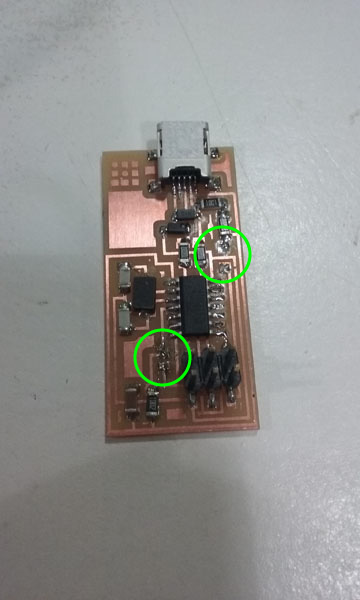
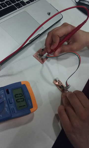
-Verify using a Multimeter that all of your connections are good.
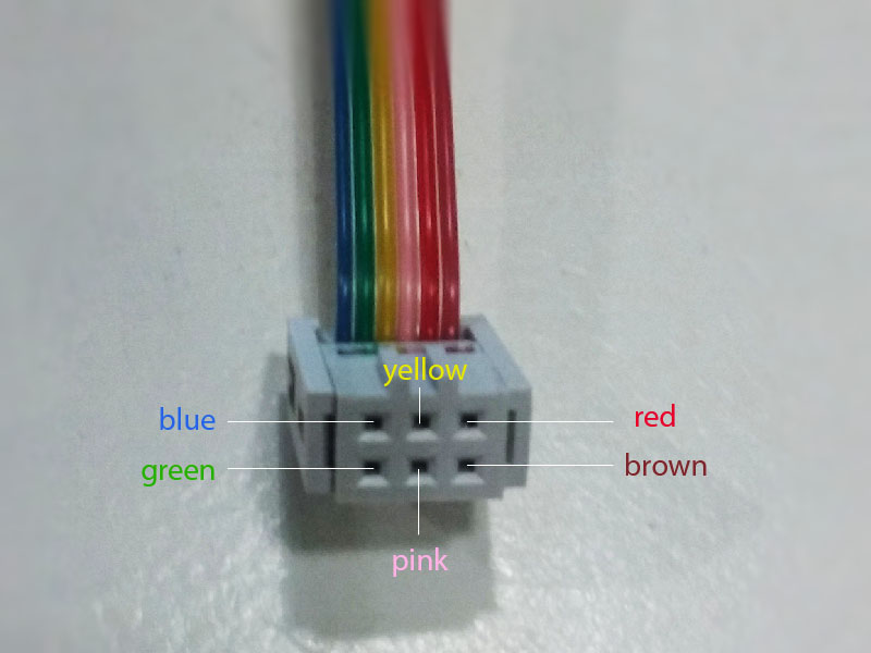
-Create a 6 connector
-Understand header's cable connections. I used a multimeter to verify correspondance between female header pins and coloured wires.
| | | | | | | | | | | | | | | | | | | | | | | | | | | | | | | | | | | | | | | | | | | | | | | | | | | | | | | | | | | | | | | | | | | | | | | | | | | | | | | | | | | | | | | | | | | | | | | | | | | | | | | | | | | | | | | | | | | | | | | | | | | | | | | | | | | | | | | | |
// INSTALLING ATTINY SUPPORT IN ARDUINO
For my assignment I used Arduino 1.6.8 and I'm using a Mac 10.9.4
-First of all, install Arduino/Genuino here
-Download this Arduino's library so your IDE will give you the options for ATtiny microprocessor.
-Go to your Arduino folder ( must be in ../Documents/Arduino ).
-Create a new sub-folder called "hardware"
-Create a new sub-folder named "attiny"
-Create a new sub-folder "avr". (../Documents/Arduino/hardware/attiny/avr)
-Paste the unzipped files that you downloaded.
-Open Arduino
-Go to "Tools" --> "Board"
-You should see now a list of Arduino boards, including ATtiny.
| | | | | | | | | | | | | | | | | | | | | | | | | | | | | | | | | | | | | | | | | | | | | | | | | | | | | | | | | | | | | | | | | | | | | | | | | | | | | | | | | | | | | | | | | | | | | | | | | | | | | | | | | | | | | | | | | | | | | | | | | | | | | | | | | | | | | | | | |
// PROGRAMMING ATTINY 44
-Connect your ISP board to your ATtinny board using your new FTDI cable.
-Make sure you VCC goes to VCC, GND to GND and so on. ( Use a multimeter! )
-Connect your FabISP board to one USB ports on your computer (USB cable), and your Hello board to another (FTDI cable).
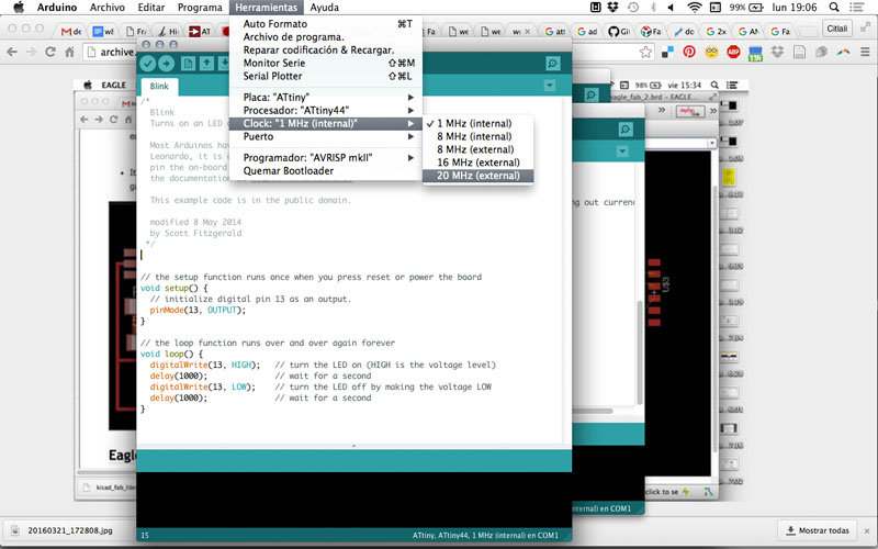
-Open Arduino, and go to "Tools" --> "Board". Select "ATtiny".
-Set Clock to "20 Mhz.". This is because the Crystal that you soldered is 20 Mhz and it is responsable for the time in the board.
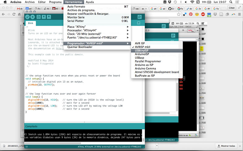
-Set the programmer to "USBtinyISP"
-Go to "Tools" --> "Burn Bootlader"
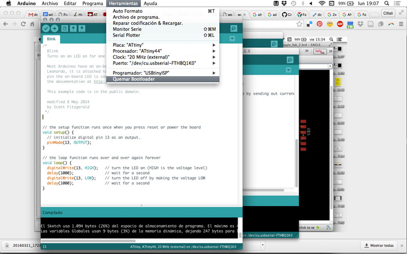
-No your board is ready to be programmed! Yey!
| | | | | | | | | | | | | | | | | | | | | | | | | | | | | | | | | | | | | | | | | | | | | | | | | | | | | | | | | | | | | | | | | | | | | | | | | | | | | | | | | | | | | | | | | | | | | | | | | | | | | | | | | | | | | | | | | | | | | | | | | | | | | | | | | | | | | | | | |
// BLINK TEST
- Open Arduino and go to "Files" --> "Examples" --> "Basics" --> "Blink".
-HighLow website has a nice diagram useful to know the translation between ATtiny and Arduino pins here.
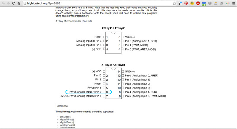
-This is an example to be used with an Arduino board, with a led in pin no. 13. You'll need to change it to pin no. 7. (Pin no. 6 in ATtiny)
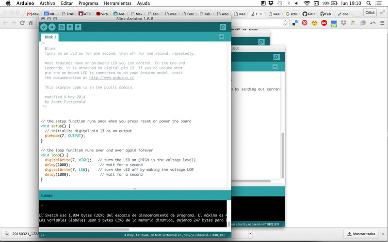
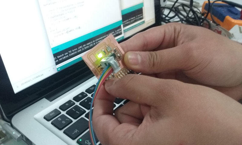
-Upload the program to your HelloBoard and if your led starts to blink, then it works!
| | | | | | | | | | | | | | | | | | | | | | | | | | | | | | | | | | | | | | | | | | | | | | | | | | | | | | | | | | | | | | | | | | | | | | | | | | | | | | | | | | | | | | | | | | | | | | | | | | | | | | | | | | | | | | | | | | | | | | | | | | | | | | | | | | | | | | | | |
This is the code that I used, by Scott Fitzgerald:
void setup() {
pinMode(7, OUTPUT);
}
void loop() {
digitalWrite(7, HIGH);
delay(1000);
digitalWrite(7, LOW);
delay(1000);
}
| | | | | | | | | | | | | | | | | | | | | | | | | | | | | | | | | | | | | | | | | | | | | | | | | | | | | | | | | | | | | | | | | | | | | | | | | | | | | | | | | | | | | | | | | | | | | | | | | | | | | | | | | | | | | | | | | | | | | | | | | | | | | | | | | | | | | | | | |
--> And a code to turn on your led using the tinny button:
int button = 3;
int led= 7;
int buttonState = 0;
void setup() {
pinMode(led, OUTPUT);
pinMode(button, INPUT);
digitalWrite(button, HIGH);
}
void loop(){
buttonState = digitalRead(button);
if (buttonState == HIGH) {
digitalWrite(led, LOW);
}
else {
digitalWrite(led, HIGH);
delay(500);
digitalWrite(led, LOW);
delay(500);
digitalWrite(led, HIGH);
delay(100);
digitalWrite(led, LOW);
delay(100);
digitalWrite(led, HIGH);
delay(100);
digitalWrite(led, LOW);
delay(100);
digitalWrite(led, HIGH);
delay(100);
digitalWrite(led, LOW);
delay(100);
digitalWrite(led, HIGH);
delay(500);
digitalWrite(led, LOW);
delay(500);
}
}
| | | | | | | | | | | | | | | | | | | | | | | | | | | | | | | | | | | | | | | | | | | | | | | | | | | | | | | | | | | | | | | | | | | | | | | | | | | | | | | | | | | | | | | | | | | | | | | | | | | | | | | | | | | | | | | | | | | | | | | | | | | | | | | | | | | | | | | | |
// Questions - What do I want to learn?
Extra exercise:
Light sensor + Servo Motor from Citlali Limonada on Vimeo.
CODE:
Citlali Hernández - Fab Academy - 2016