hola soy un mensaje secreto wiwiwi wawawa
COMPUTER - CONTROLLED MACHINING
Assignment: Make something big.
| | | | | | | | | | | | | | | | | | | | | | | | | | | | | | | | | | | | | | | | | | | | | | | | | | | | | | | | | | | | | | | | | | | | | | | | | | | | | | | | | | | | | | | | | | | | | | | | | | | | | | | | | | | | | | | | | | | | | | | | | | | | | | | | | | | | | | | | |
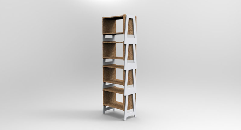
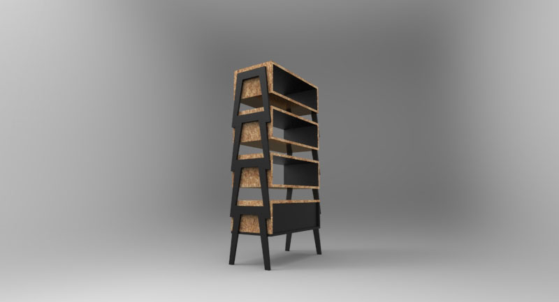
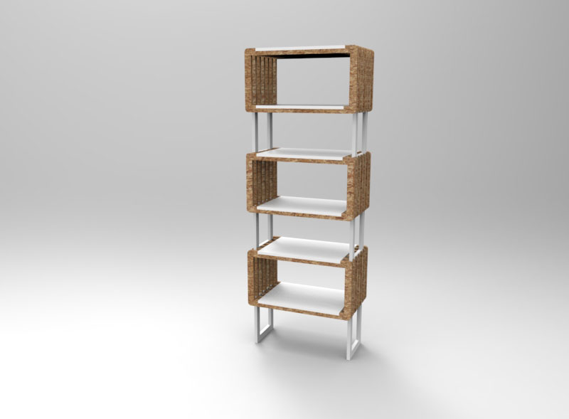
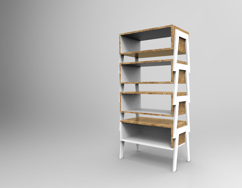
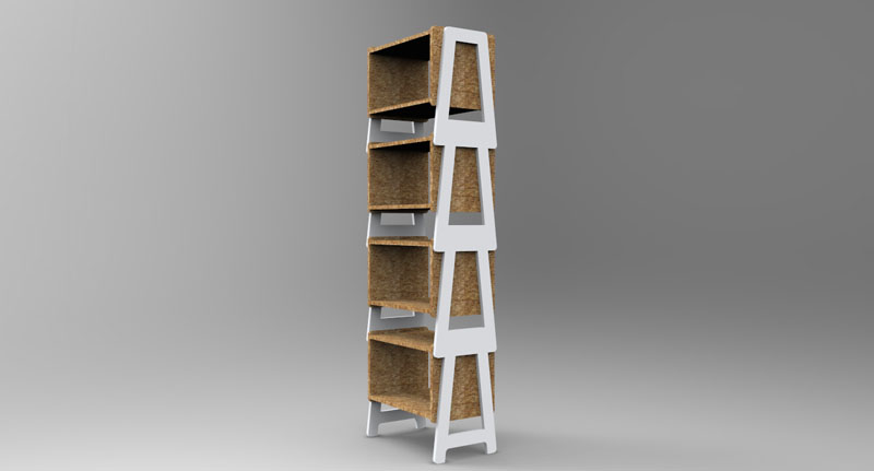
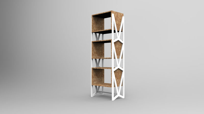
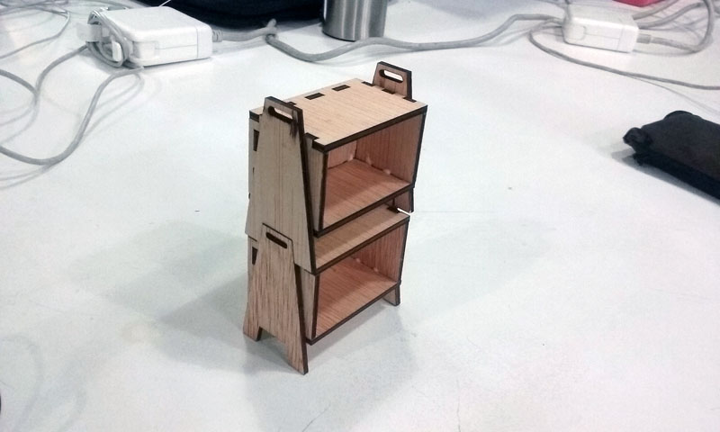
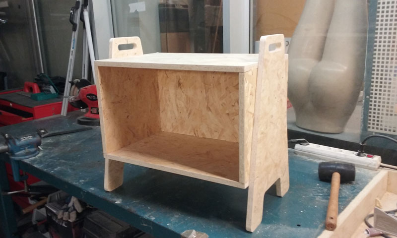
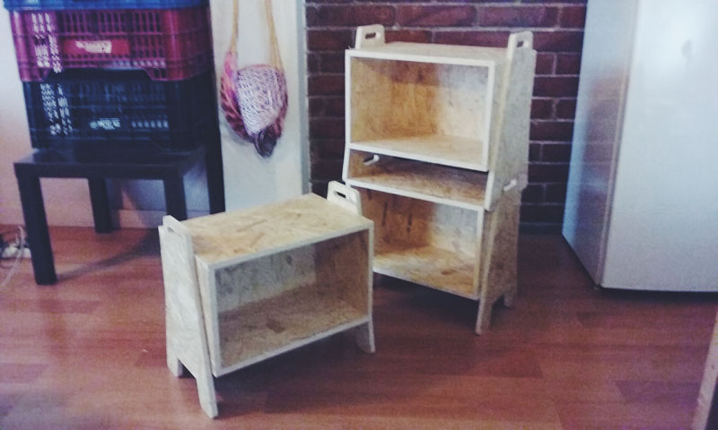
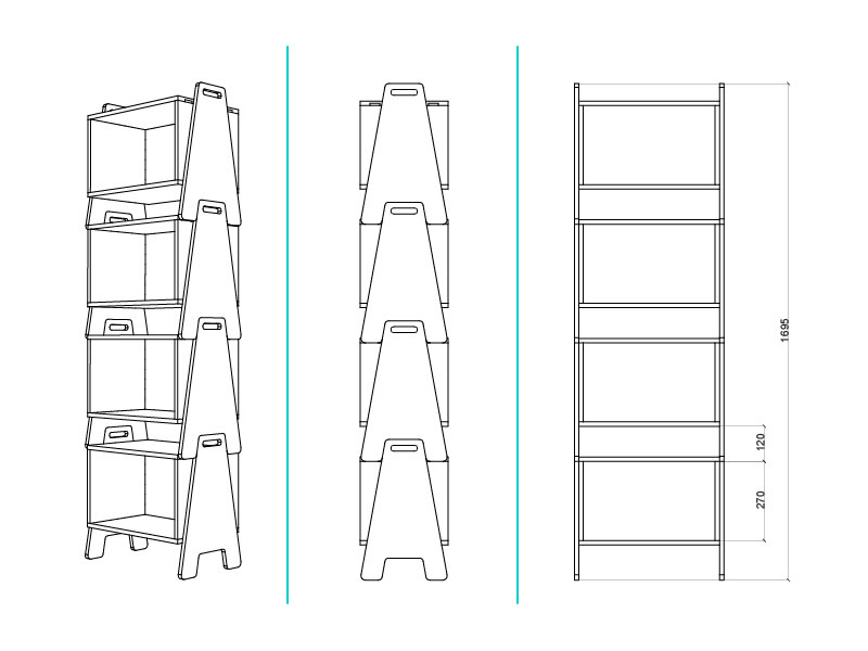
For this assignment I designed a storage seat that can be stacked and transformed into shelves. I mainly used Rhinoceros for the design and PartWorks for the machining strategy. I used 15 Mm. OSB.
Machines used: Multicam laser, Precix and ShopBot.
//Some notes and recommendations:
| | | | | | | | | | | | | | | | | | | | | | | | | | | | | | | | | | | | | | | | | | | | | | | | | | | | | | | | | | | | | | | | | | | | | | | | | | | | | | | | | | | | | | | | | | | | | | | | | | | | | | | | | | | | | | | | | | | | | | | | | | | | | | | | | | | | | | | | |
>>3D SKETCHING
My idea was to design modules to be easily transported home.
Design considerations:
Some quick 3d sketches using Rhino and Keyshot:
>>>LASER CUT MODEL:
To understand the proportion of my design I made a scale model using laser cutting.
| | | | | | | | | | | | | | | | | | | | | | | | | | | | | | | | | | | | | | | | | | | | | | | | | | | | | | | | | | | | | | | | | | | | | | | | | | | | | | | | | | | | | | | | | | | | | | | | | | | | | | | | | | | | | | | | | | | | | | | | | | | | | | | | | | | | | | | | |
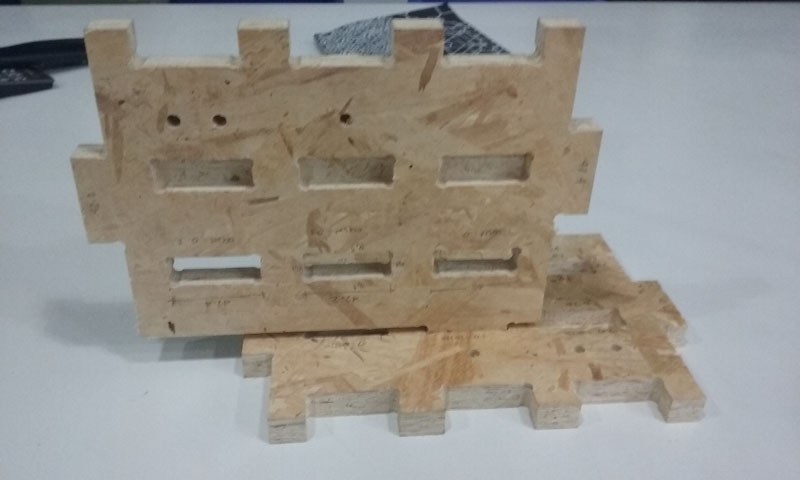
>>JOINTS TEST
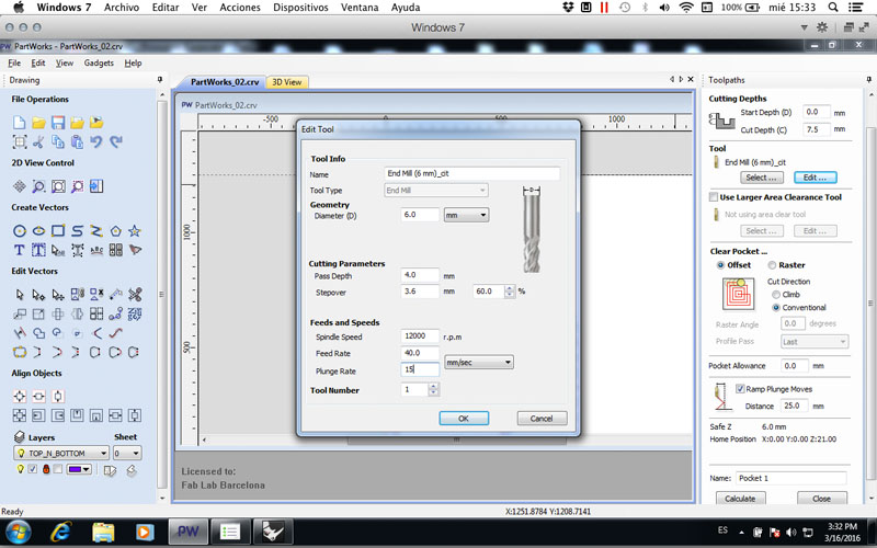
I was trying to make "invisible" joints by milling pockets down to 7.5 Mm. (Half of the OSB thickness). I made a joints test using 0.0 Mm., 0.1 Mm. and 0.2 gaps.
What I found is that using 0.0 Mm. offset works, but just because I don't trust at all in homogeneous thicknesses and I wanted to make sure not to sand forever I used the 0.1 Mm. one.
| | | | | | | | | | | | | | | | | | | | | | | | | | | | | | | | | | | | | | | | | | | | | | | | | | | | | | | | | | | | | | | | | | | | | | | | | | | | | | | | | | | | | | | | | | | | | | | | | | | | | | | | | | | | | | | | | | | | | | | | | | | | | | | | | | | | | | | | |
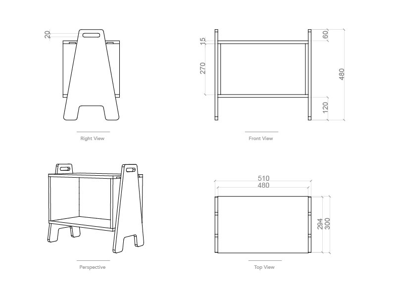
>>DESIGN
Three modular seat/shelves fitted on the complete OSB sheet, so I decided to cut only one at first in order to see if there were things to be improved, etc.
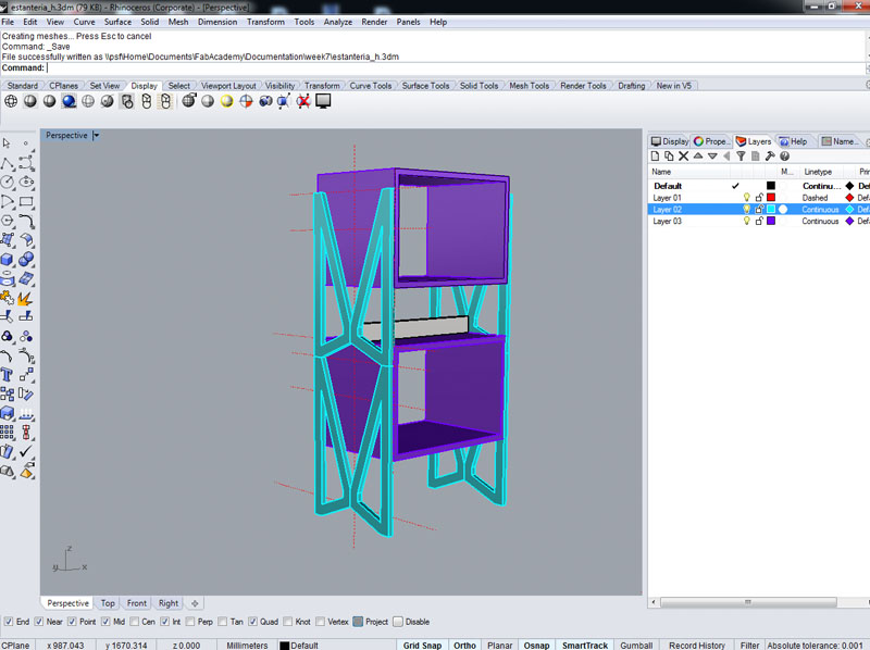
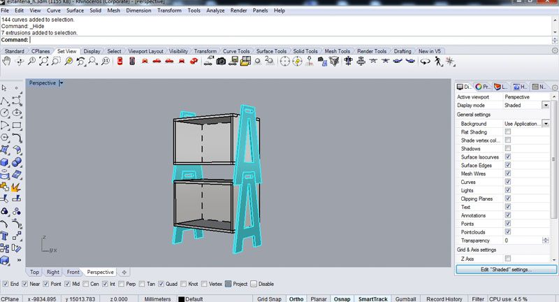
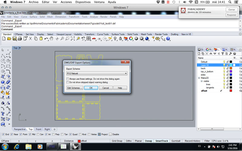
I modeled everything in Rhino, and I used different coloured layers for every part.
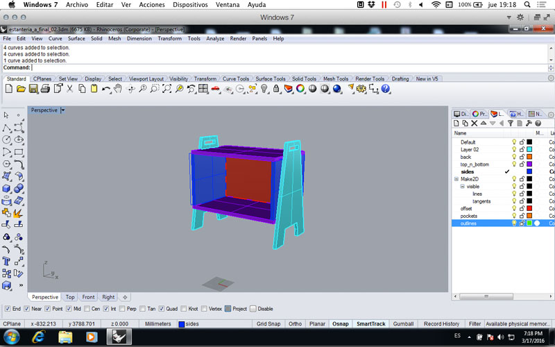
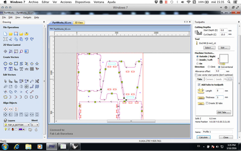
I created a rectangle of 2550x1250 Mm. and made sure that my first module only used 1/3 of my material. I recommend to leave an internal offset of the osb sheet of aprox 15 Mm. This is useful for future screws.
| | | | | | | | | | | | | | | | | | | | | | | | | | | | | | | | | | | | | | | | | | | | | | | | | | | | | | | | | | | | | | | | | | | | | | | | | | | | | | | | | | | | | | | | | | | | | | | | | | | | | | | | | | | | | | | | | | | | | | | | | | | | | | | | | | | | | | | | |
>>PARTWORKS: MACHINING STRATEGY
Before to start, I think it is important for you to understand the steps to follow when milling your designs. This will help you when making the strategy in the software of your choice and deciding which profile toolpath to use.
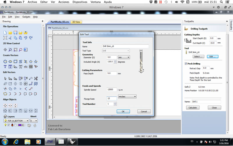
- 1. Drilling with 3 Mm. diameter drill bit. Toolpath to use: Drilling.
- 2. Put screws by hand using a driller.
- 3. Removing material for pockets. Toolpath to use: Pocketing.
- 4. Cutting. Toolpath to use: Profile.
- 5. Remove screws by hand using a driller.
- 6. Removing tabs by hand using a hammer and a chisel.
- 7. Removing material.
- 8. Clean the machine.
Using PARTWORKS:
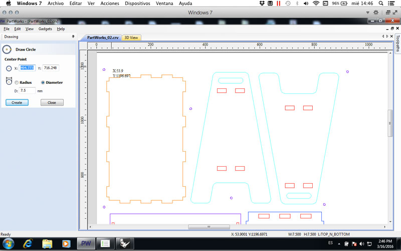
Now you are ready to create toolpaths.
| | | | | | | | | | | | | | | | | | | | | | | | | | | | | | | | | | | | | | | | | | | | | | | | | | | | | | | | | | | | | | | | | | | | | | | | | | | | | | | | | | | | | | | | | | | | | | | | | | | | | | | | | | | | | | | | | | | | | | | | | | | | | | | | | | | | | | | | |
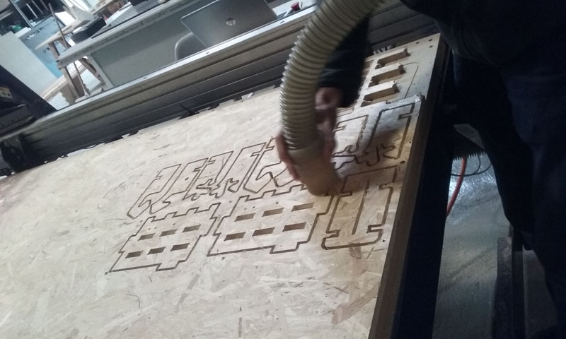
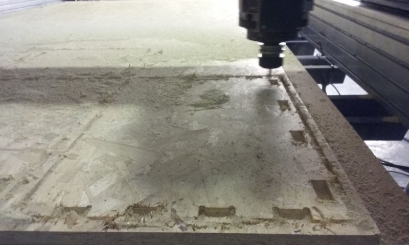
>>SHOPBOT
| | | | | | | | | | | | | | | | | | | | | | | | | | | | | | | | | | | | | | | | | | | | | | | | | | | | | | | | | | | | | | | | | | | | | | | | | | | | | | | | | | | | | | | | | | | | | | | | | | | | | | | | | | | | | | | | | | | | | | | | | | | | | | | | | | | | | | | | |
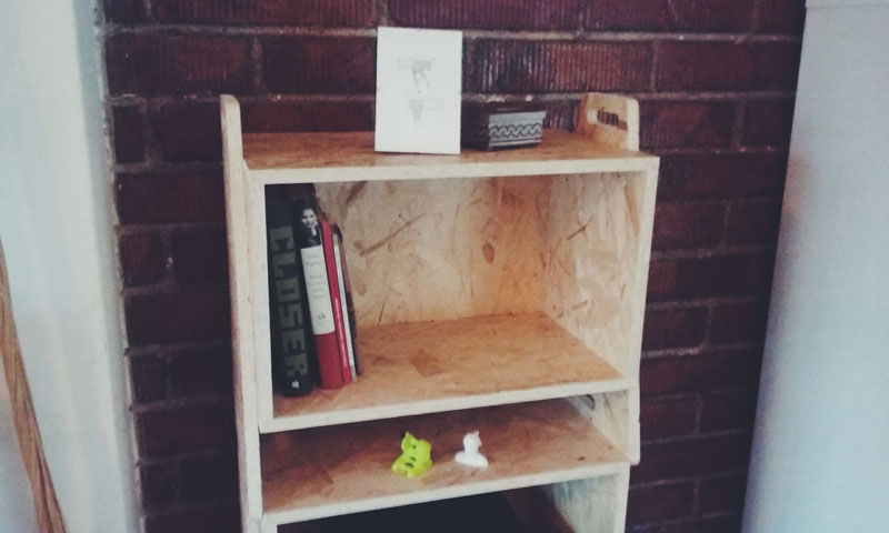
>>1st module: FINISHES AND RESULTS
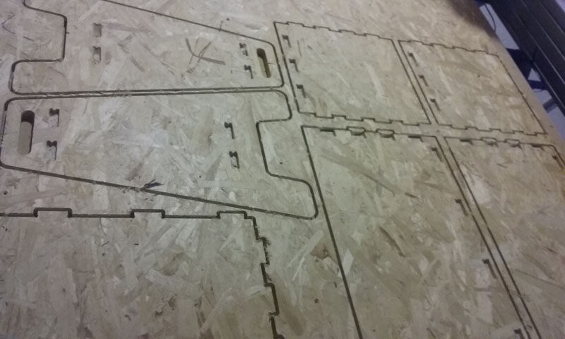
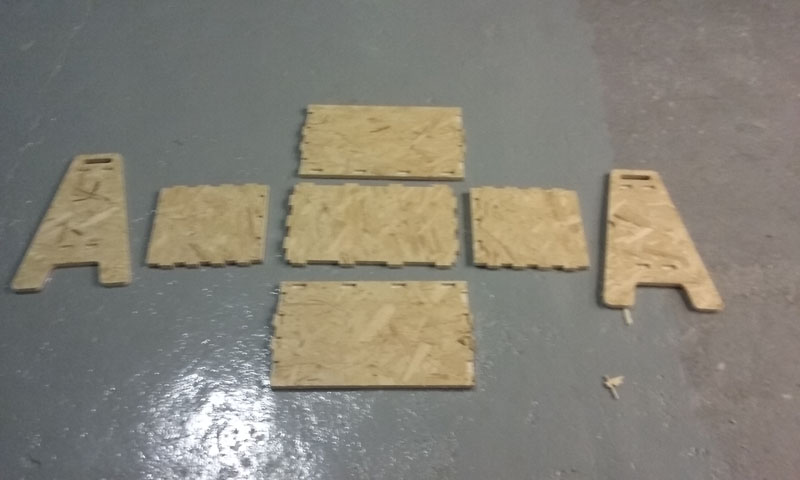
Pieces:
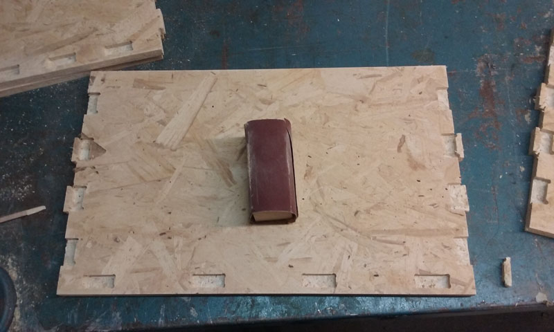
Sanding:
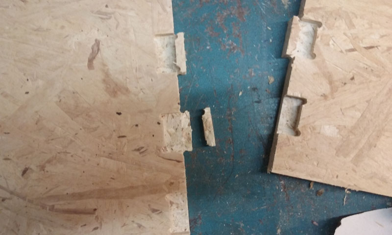
PROBLEM 1! I left a small space between pockets and some little pieces for joints, so my osb broke.
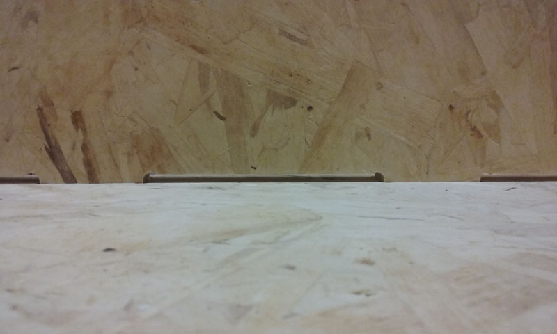
PROBLEM 2! For some reason my pockets didn't arrived to 7.5 Mm. so I had to cut my joints using the circular saw. ( Thanks to Goriwho helped me to do this! )
Evidence picture: Joints didn't reach the bottom of the wood.
First module assembled:
| | | | | | | | | | | | | | | | | | | | | | | | | | | | | | | | | | | | | | | | | | | | | | | | | | | | | | | | | | | | | | | | | | | | | | | | | | | | | | | | | | | | | | | | | | | | | | | | | | | | | | | | | | | | | | | | | | | | | | | | | | | | | | | | | | | | | | | | |
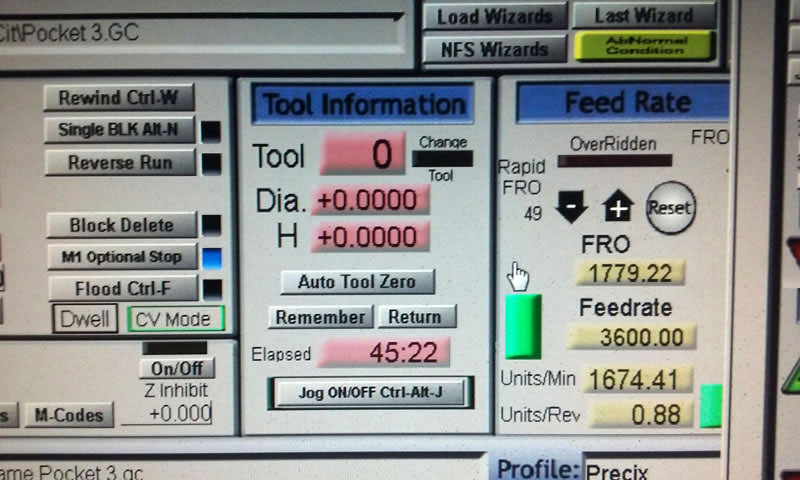
>>2ND AND THIRD MODULE using the PRECIX machine.
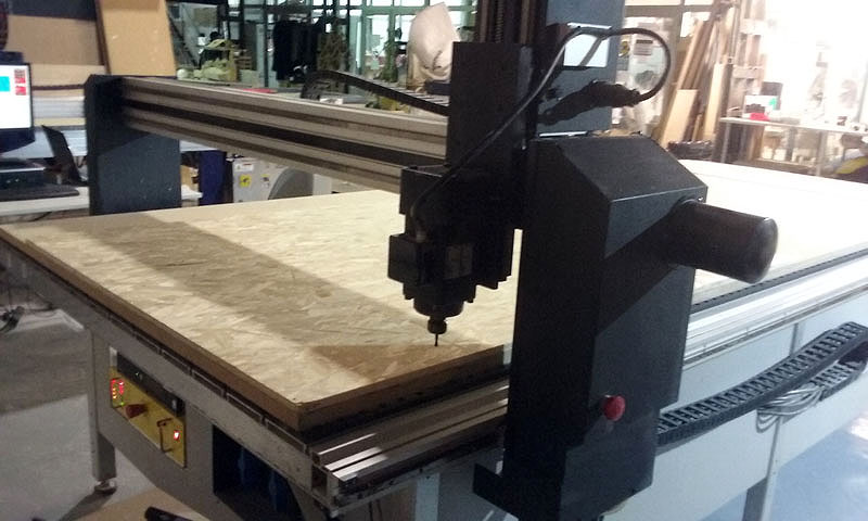
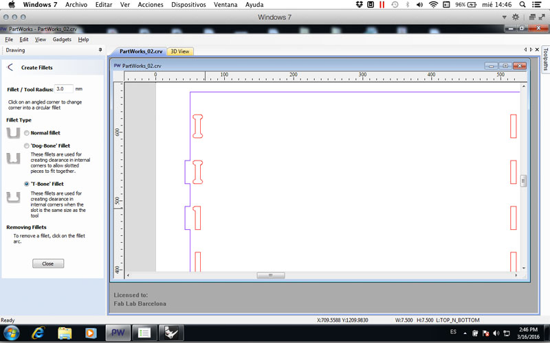
I made some changes to my design and I followed the same Partworks strategy. This time I used T bones which are not visible in the final assembly. :)
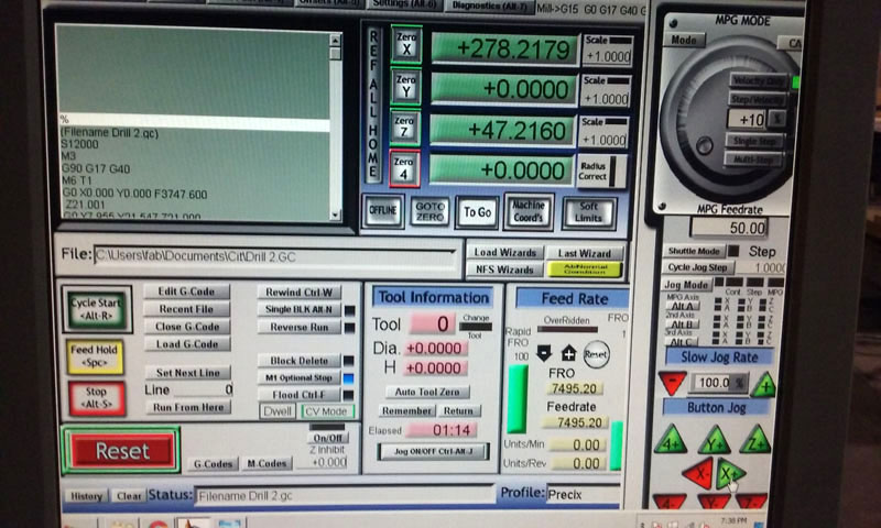
Important! Load your file and make sure it appears in the Mach3 CNC software window. I didn't checked and I sent Joao's screws file!
The good thing about Mach 3 is that you can move the speed of the steppers - spindle directly.
At first Ferdi and I put 100% of the speed, but i saw a lot of ugly burrs so I slowed the steppers to 50%. Yes it took more time but I had to sand less and the general finishes were better.
A speed test would be also great to do before milling everything!
I used again a 0.1 offset (gap) in the joints.
PROBLEM: Althoug I used a 0.1 gap, my joints didn't fit well. I am not sure why did this happen, byt I think it has something to do with the cutting end mill bit.
LESSON LEARNED: Make a joints test for every machine that you use.
I solved this problem by using a Dremel and making the pockets a little bit bigger. ( Not desirable process )
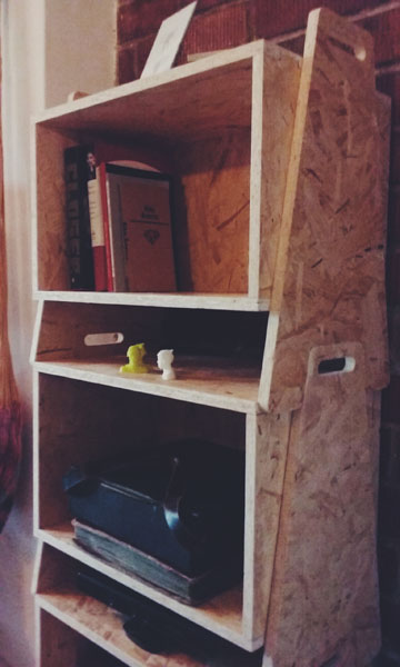
>>FINAL RESULTS:

| | | | | | | | | | | | | | | | | | | | | | | | | | | | | | | | | | | | | | | | | | | | | | | | | | | | | | | | | | | | | | | | | | | | | | | | | | | | | | | | | | | | | | | | | | | | | | | | | | | | | | | | | | | | | | | | | | | | | | | | | | | | | | | | | | | | | | | | |
| | | | | | | | | | | | | | | | | | | | | | | | | | | | | | | | | | | | | | | | | | | | | | | | | | | | | | | | | | | | | | | | | | | | | | | | | | | | | | | | | | | | | | | | | | | | | | | | | | | | | | | | | | | | | | | | | | | | | | | | | | | | | | | | | | | | | | | | |
| | | | | | | | | | | | | | | | | | | | | | | | | | | | | | | | | | | | | | | | | | | | | | | | | | | | | | | | | | | | | | | | | | | | | | | | | | | | | | | | | | | | | | | | | | | | | | | | | | | | | | | | | | | | | | | | | | | | | | | | | | | | | | | | | | | | | | | | |
Download my files:
Citlali Hernández - Fab Academy - 2016