hola soy un mensaje secreto wiwiwi wawawa
WEEK 6: ELECTRONICS DESIGN
| | | | | | | | | | | | | | | | | | | | | | | | | | | | | | | | | | | | | | | | | | | | | | | | | | | | | | | | | | | | | | | | | | | | | | | | | | | | | | | | | | | | | | | | | | | | | | | | | | | | | | | | | | | | | | | | | | | | | | | | | | | | | | | | | | | | | | | | |
| | | | | | | | | | | | | | | | | | | | | | | | | | | | | | | | | | | | | | | | | | | | | | | | | | | | | | | | | | | | | | | | | | | | | | | | | | | | | | | | | | | | | | | | | | | | | | | | | | | | | | | | | | | | | | | | | | | | | | | | | | | | | | | | | | | | | | | | |
| | | | | | | | | | | | | | | | | | | | | | | | | | | | | | | | | | | | | | | | | | | | | | | | | | | | | | | | | | | | | | | | | | | | | | | | | | | | | | | | | | | | | | | | | | | | | | | | | | | | | | | | | | | | | | | | | | | | | | | | | | | | | | | | | | | | | | | | |
// Notes and recommendations:
- All the information that you will need is in this tutorial: I'm a link to the tutorial! :D
- Before putting your hands to work, read about the basics of electronics and understand what you can do with the Hello PCB. Neil recommended this beautiful book: "The arts of electronics." by Paul Horowitz and Winfield Hill.
- Look for the datasheets of every component of the board. What you will find is that the most important one is the Attiny 44, am 8 bit microcontroler designed with 14 pins. Basically this is a little brain that can manage to follow simple intructions depending on the program that you code for it. You can read and download Attiny's 44 data sheet here.
- Don't just copy the schematic, try to understand everything that you do.
// Software installation:
- Download EAGLE, a PCB Design Software. You will have to install the freeware version.
- Download and import the fab libraries, which contains all of the components that Fab Labs use and that you can later on add to your circuit design.
- Drag the fab library folder inside "../EAGLE-7.5.0/lbr".
For this assignment I added only a button and a led, I wanted to try to make a 2nd board adding female headers, but I just didn't have time and a lot of problems appeared during my process.
| | | | | | | | | | | | | | | | | | | | | | | | | | | | | | | | | | | | | | | | | | | | | | | | | | | | | | | | | | | | | | | | | | | | | | | | | | | | | | | | | | | | | | | | | | | | | | | | | | | | | | | | | | | | | | | | | | | | | | | | | | | | | | | | | | | | | | | | |
//EAGLE
>>SCHEMATIC
- Open a new project, I clicked on "Schematic". You will start wokring with this view, but EAGLE at the same time will create another "board" window where you will work later on the drawing for the PCB. Don't close it!
- Activate the fab library that you downloaded by going to "library" and then click "use".
- Select the fab library and click over "open.
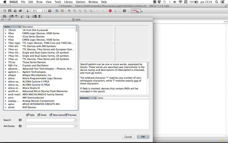
In the command line, write "add", a window like this will appear, and then you'll have to select one by one all of the components for your board.
Components:
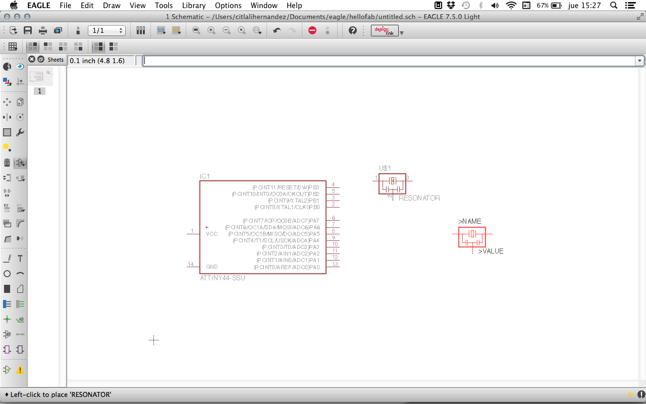
This is how your schematic will start to look:
- You'll need to add some GND and VCC component from the general EAGLE library.
- Once you have added all the components, use the "electrical connections" tool and create your connections between them.
- I did everything by looking at Neil's circuit board and not to the schematic example. It was hard ant took me a while, but it was a good way to understand the assignment.
- Use 1206 size components as they have a good space that will allow you to solder in a comfortable way.
- I mainly used "move", "rotate", "group selection" commands to put in the right position my components, and later on I also used" name", "label" and "value" commands. This second part will allow you not only to recognize everything but to tell EAGLE where the connections have to go.
-save
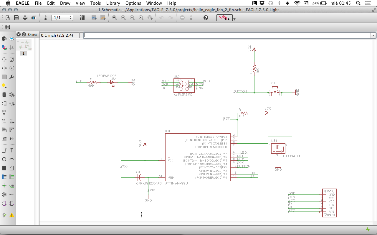
This is how my finished schematic window looked like:
| | | | | | | | | | | | | | | | | | | | | | | | | | | | | | | | | | | | | | | | | | | | | | | | | | | | | | | | | | | | | | | | | | | | | | | | | | | | | | | | | | | | | | | | | | | | | | | | | | | | | | | | | | | | | | | | | | | | | | | | | | | | | | | | | | | | | | | | |
>>BOARD
- Go to your board window or go to "File--switch to board"
- You'll find your components and yellow lines that show where they have been connected, this will guide you to make the paths.
- Use the group selction tool and move everything inside the white line box.
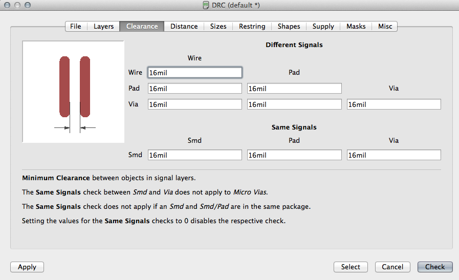
- To respect the right distances for the 1/64 drill, go to the command line and write "DRC".Select the Clearance tab and make sure all values are 16mil
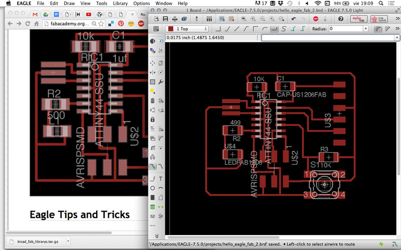
- Move every component to it's right position. I based my drawing on the tutorial example and tried to leave the same distances between components.
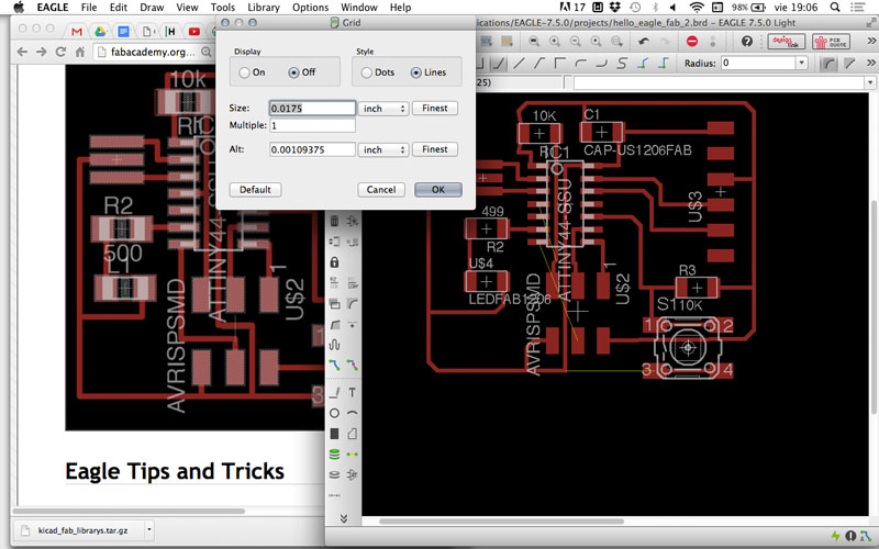
- I suggest you to change the grid values so this can allow you to move your drawing respecting tolerances for you SRM-20 tool.
- Use de "DRC" command to verify that the space between your traces are enough for the 1/64 tool.
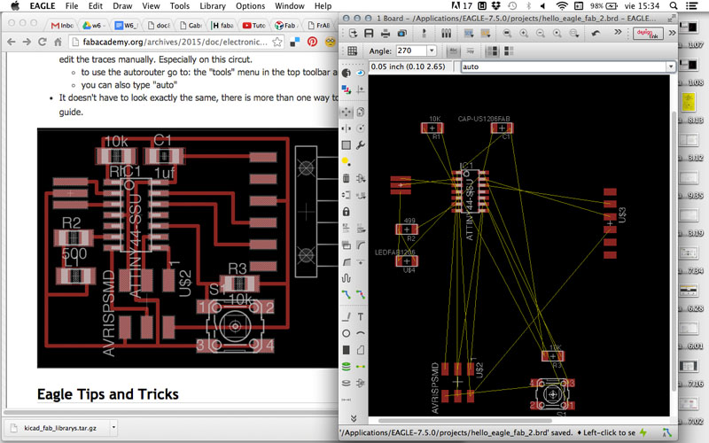
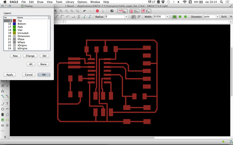
- This is how my board window looked like when finished:
- Hide all layers and export your design as a PNG with a 500 DPI resolution. The higher resolution, the better fabmodules will work.
| | | | | | | | | | | | | | | | | | | | | | | | | | | | | | | | | | | | | | | | | | | | | | | | | | | | | | | | | | | | | | | | | | | | | | | | | | | | | | | | | | | | | | | | | | | | | | | | | | | | | | | | | | | | | | | | | | | | | | | | | | | | | | | | | | | | | | | | |
>>MACHINING
- For cutting my PCB I followed the same process that we learned in week No.4. But this time I had some problems.
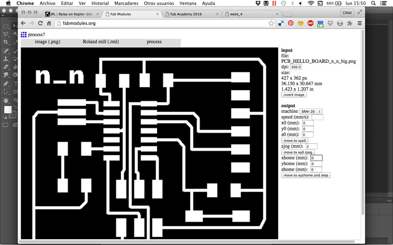
- I used fabmodules
to export .rml files.- First exported my .rml file (for a Roland SRM-20) for the outter line, using the 1/64 tool values. This is used just as a test that will help you to see if your board fits in your material.
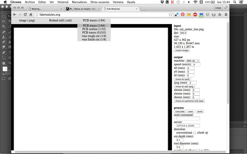
-Second. I exported my .rml file for the traces, using the values for the 1/64 tool. 50% overlap, 4 offsets, -0.1 depth.
- Third: I exported my .rml file for the cutting outter line, using the 1/32 tool values. I changed cut depth to 0.5, and stock thickness to1.5.
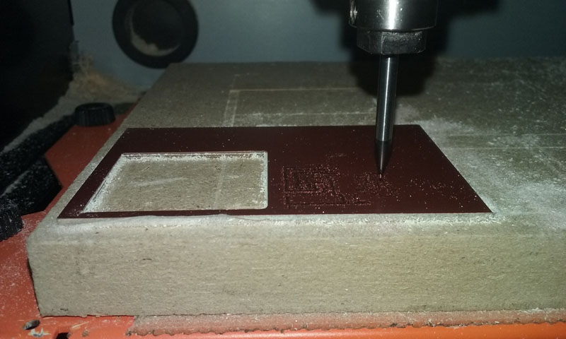
*PROBLEMS!
--> No. 1: As you can see in the picture below, when making the machining, the traces process didn't went well. The tool didn't went deep enough so it didn't remove the copper.
*SOLUTION: We moved down a little bit the tool using the VPanel software moving Z axis with a cursor step of x1.
Failed traces:
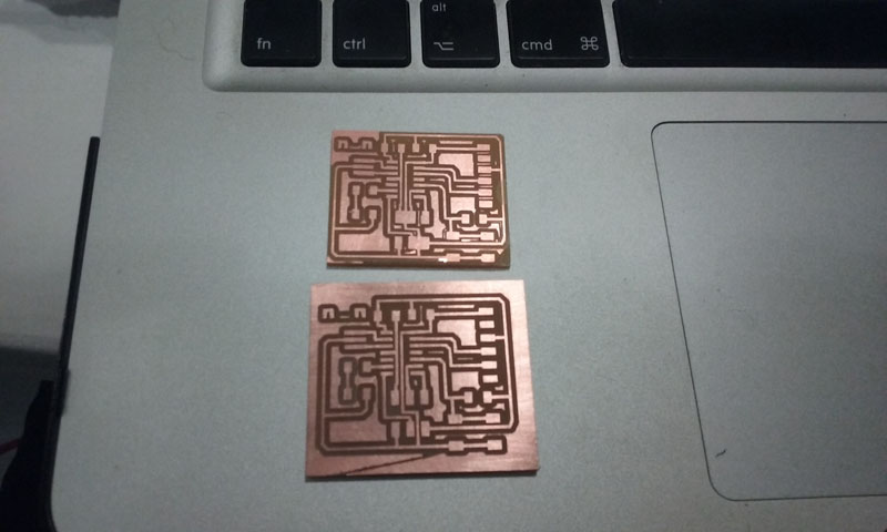
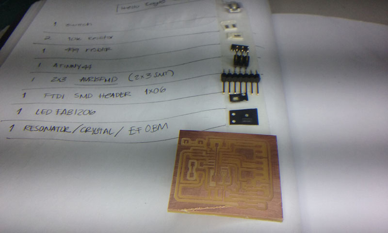
--> No. 2 The drawing of my board design was too close to the edge, so when I tried to remove it from the whole copper material, my board BROKE. :(
*SOLUTION: Leave a bigger offset for your board.
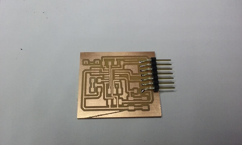
- I had to repeat the process to make a 2nd board.
This is my 1st broken board compared to the 2nd one which resulted bigger but more comfortable to get out and to solder. :( :( :(
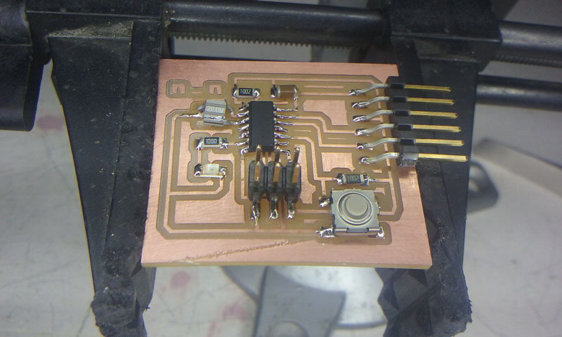
You can see the "n_n" logo, which is the name of art collective in where I actually participate. My final project is one part of a project we are developing and hopefully finishing this year. :D
| | | | | | | | | | | | | | | | | | | | | | | | | | | | | | | | | | | | | | | | | | | | | | | | | | | | | | | | | | | | | | | | | | | | | | | | | | | | | | | | | | | | | | | | | | | | | | | | | | | | | | | | | | | | | | | | | | | | | | | | | | | | | | | | | | | | | | | | |
>>SOLDERING
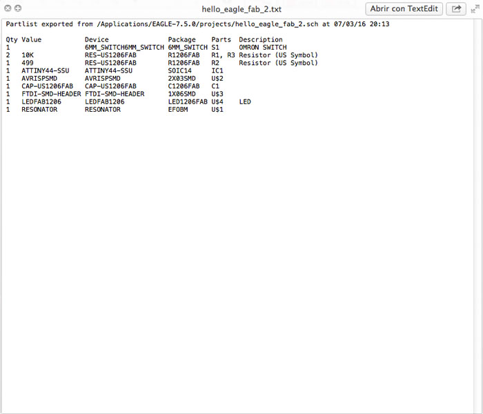
-First of all gather all your components. You can use " __ " command and EAGLE will show a window with a list of your used components. Then you can save it as a .txt just as I did.
- I have to say that I felt more comfortable this time when soldering my board, but I did a stupid mistake which was counting 7 pins instead of 6 and then solder them.
- I solved this problem with Ferdi's help, using a cutter. :D
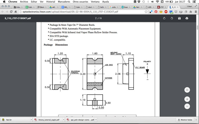
- One important thing to take into consideration is that the led as you for sure know, has a green line or a dot that tells you where the cathode is ( meaning that the side goes to the ground). I consulted the datasheet of my led to be sure about this information.
-And finally, this is how my board looks like:
- To be sure that your board is working, use a multimeter.
| | | | | | | | | | | | | | | | | | | | | | | | | | | | | | | | | | | | | | | | | | | | | | | | | | | | | | | | | | | | | | | | | | | | | | | | | | | | | | | | | | | | | | | | | | | | | | | | | | | | | | | | | | | | | | | | | | | | | | | | | | | | | | | | | | | | | | | | |
>>FILES
-EAGLE: ---------here---------
-PNGS: ---------here---------
-RMLS: ---------here---------
Citlali Hernández - Fab Academy - 2016