hola soy un mensaje secreto wiwiwi wawawa
WEEK 3: ELECTRONICS PRODUCTION
| | | | | | | | | | | | | | | | | | | | | | | | | | | | | | | | | | | | | | | | | | | | | | | | | | | | | | | | | | | | | | | | | | | | | | | | | | | | | | | | | | | | | | | | | | | | | | | | | | | | | | | | | | | | | | | | | | | | | | | | | | | | | | | | |
Some basics of electronics:
There are different ways to create a PCB, here I make a little description od some of them:
| | | | | | | | | | | | | | | | | | | | | | | | | | | | | | | | | | | | | | | | | | | | | | | | | | | | | | | | | | | | | | | | | | | | | | | | | | | | | | | | | | | | | | | | | | | | | | | | | | | | | | | | | | | | | | | | | | | | | | | | | | | | | | | | |
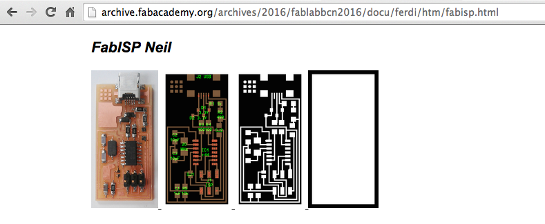
For this assignment we all worked on the FabISP, an in-system programmer for AVR microcontrolers. With this tiny device we will be able to "talk" to other devices and program them using a USB cable and 6 pin IDC to 6 pin IDC cables. It is based on the USBtiny and V-USB firmwares.
// PREPARING YOUR FILES
1.- Get the FabISP files that were going to be sent to Monofab milling machine.
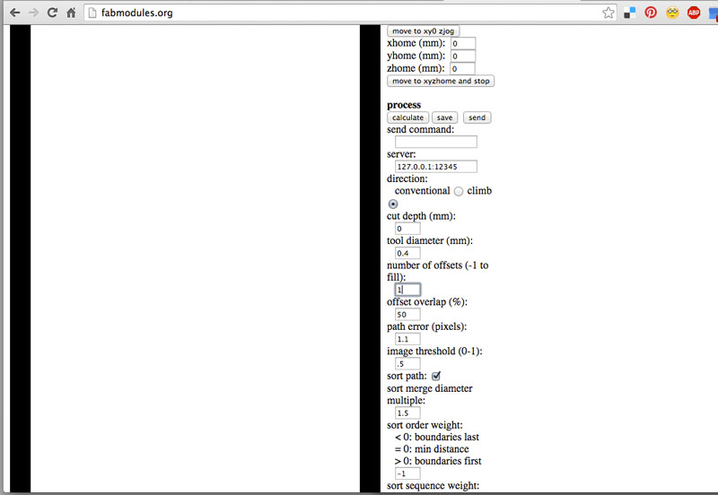
2. Outline test file: Go to fabmodules.org select "image (png)" and upload the black rectangle. Then select Roland mill (.rml) and verify that the size in mm or in is what you need. In this case is 22.987 x 45.214 Mm. X0,y0,z0, xhome, yhome and zhome should be in 0. Select PBC traces with the 1/64 inches tool. Output machine SRM-20. Speed will automatically go to 4, and all you have to change is the number of offsets to 1 and cut depth to zero. With this file you will tell the machine to move without touching the board, just for you to verify that your future pcb fits in the copper board. Save the file.
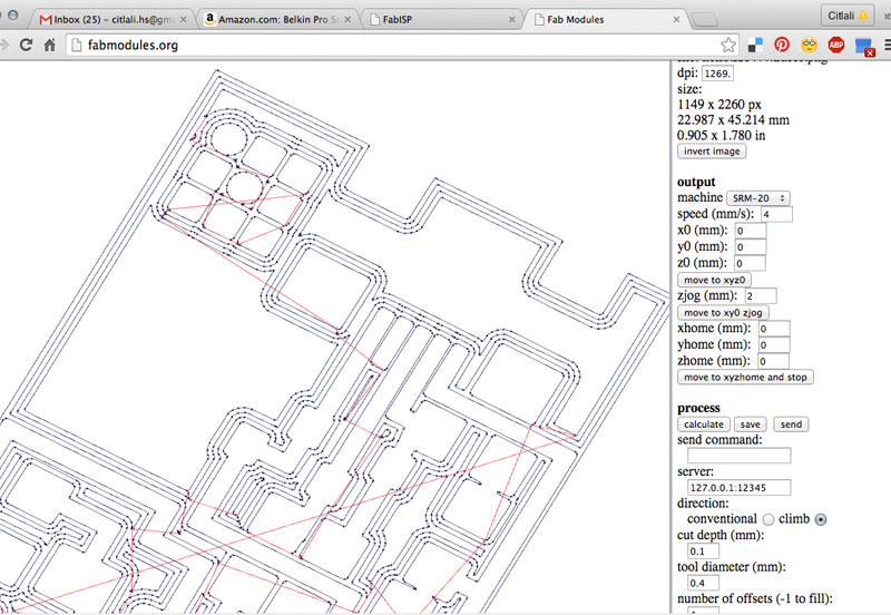
3. Traces file: Go to fabmodules.org select "image (png)" and upload thetraces iamge file. Then select Roland mill (.rml) and verify that the size in mm or in is what you need. In this case is 22.987 x 45.214 Mm. X0,y0,z0, xhome, yhome and zhome should be in 0. Select PBC traces with the 1/64 inches tool. Output machine SRM-20. Speed will automatically go to 4, and all you have to change is the number of offsets to 4, offset overlap to 50%, cut depth to 0.1 With this file you will tell the machine to mill the board following four offsets paths around what appears in white. Another way is to put -1 in number of offsets, with this, the machine understand that it has to mill everything that appears in black. If you click over "calculate", the fabmodule online program will make a simulation on how the machine will move. If everything is ok, save the file.
4. Outline cut file: Same steps, but using again the rectangular image file, select 1/32 inches tool, number of offsets to 1, cut depth 0.5, stock thickness 1.5.
5. Upload your files to IAAC Cloud.
| | | | | | | | | | | | | | | | | | | | | | | | | | | | | | | | | | | | | | | | | | | | | | | | | | | | | | | | | | | | | | | | | | | | | | | | | | | | | | | | | | | | | | | | | | | | | | | | | | | | | | | | | | | | | | | | | | | | | | | | | | | | | | | | |
//MACHINING
1. Put your copper board over the sacrifice MDF material. It should be glued using a double sided tape.
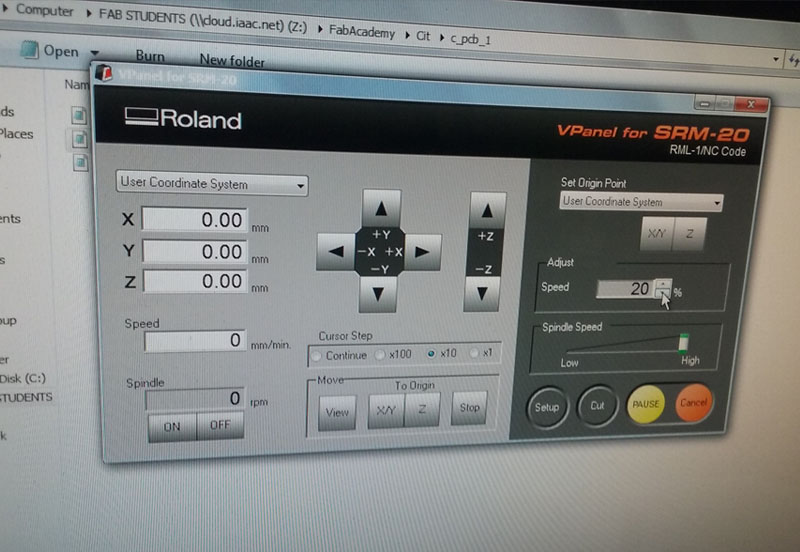
2. Open VPanel, the Roland software to manipulate the machine.
3. Move your tool using the -X, +X, +Y and -Y arrows to your new desired "home". To set this new home, click over X/Y button.
4. Move your 1/64 tool down using the arrows. x10 and x1 Cursor steps are recommended. When the tool is almost touching the copper surface, open the machine and with your hands move the tool (using Allen key) until it touches the copper surface. Click over Z button to set this axis to 0.
5. Santi recommended to set the speed to 20%. In this way you can first watch how the machine is working, and if there is something wrong, you will have time to stop the machine. If everything seems to be going well, then you can change the speed to 100%.
6.Click over "cut", and select your "outline test" file. Send it.
7. If everything went good, then again click over "cut", select your "Traces" file and send it.
8. Change tool to 1/32. And set again the Z axis to the 0 home.
9. Click over "cut", select your "outline cut" file, and send it.
10. Remove your board, and clean it.
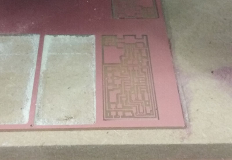
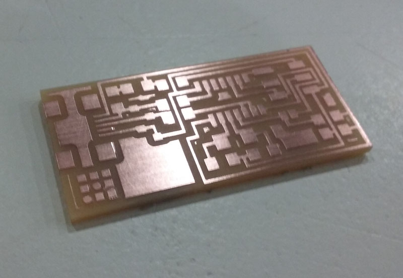 This is my copper board! :)
| | | | | | | | | | | | | | | | | | | | | | | | | | | | | | | | | | | | | | | | | | | | | | | | | | | | | | | | | | | | | | | | | | | | | | | | | | | | | | | | | | | | | | | | | | | | | | | | | | | | | | | | | | | | | | | | | | | | | | | | | | | | | | | | |
//SOLDERING
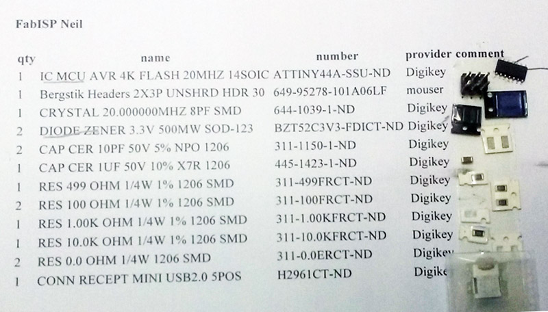
First, gather all the components. They were all available at the FabLab inventory. The complete list with the names, quantity, number and provider is here, in Ferdi's FabAcademy 2016 site.
If this is your first time soldering, then please practice using old boards that your fab have for sure. Take a look at this video recommended by Ferdi:
Start from the shorter components.
The most difficult part is the ultra tiny legs from the usb connector.
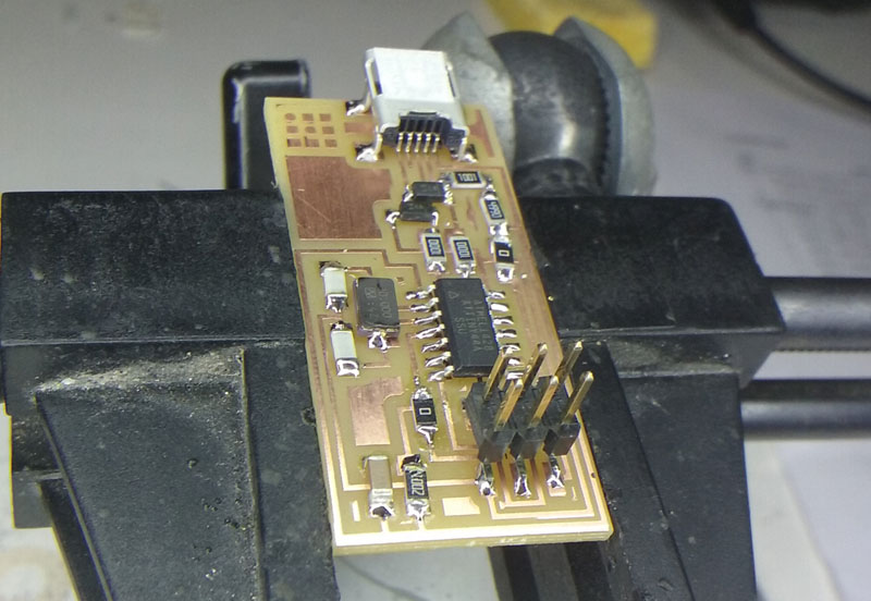 This is my board almost finished. I was about to solder those usb connector legs.
| | | | | | | | | | | | | | | | | | | | | | | | | | | | | | | | | | | | | | | | | | | | | | | | | | | | | | | | | | | | | | | | | | | | | | | | | | | | | | | | | | | | | | | | | | | | | | | | | | | | | | | | | | | | | | | | | | | | | | | | | | | | | | | | |
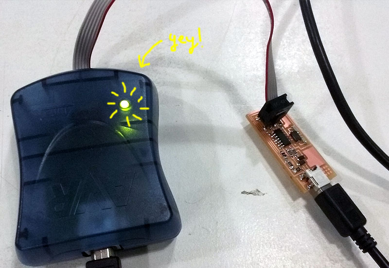
// TEST YOUR BOARD
Test your board and check if you soldered everything good.
Plug a 6-pin programming header into your 3x2 header, and connect a USB-Miniusb using your computer.
Green Light means everything is soldered orrectly.
Yellow Light menas the board is getting power but there's something wrong with your 6 pin header.
Red Light means that everything is not getting power.
Mine went OK!
| | | | | | | | | | | | | | | | | | | | | | | | | | | | | | | | | | | | | | | | | | | | | | | | | | | | | | | | | | | | | | | | | | | | | | | | | | | | | | | | | | | | | | | | | | | | | | | | | | | | | | | | | | | | | | | | | | | | | | | | | | | | | | | | |
//PROGRAMMING
1. Go to FabISP: Programming, you'll find a nice tutorial to follow. I am using a Mac 10.9.4, so if you follow my documentation take that into consideration, but there are instructions for Ubuntu and Windows users as well.
2. Download and install crosspack AVR here and make sure you also have XCode.
3. You'll need also to install the adequate firmware which in my case was the one called " FABISP Firmware for MacOS 10.8.2. " I'm actually using Mavericks and had no problems.
Save the firmware in your desktop, go to terminal and navigate to uour new firmware folder.
4. Open the terminal and follow these instructions:
cd Desktop/fabISP_mac.0.8,2_firmware
type: make clean
type: make hex
type: make fuse
type: make program
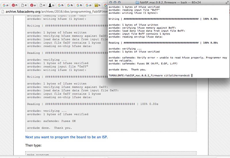
If you didn't receive any error message and you could get to this point, then you and your new PCB are ready to talk to other devices !
One final step is recommended, and it is to remove the 0 ohm resistors (or jumpers).
| | | | | | | | | | | | | | | | | | | | | | | | | | | | | | | | | | | | | | | | | | | | | | | | | | | | | | | | | | | | | | | | | | | | | | | | | | | | | | | | | | | | | | | | | | | | | | | | | | | | | | | | | | | | | | | | | | | | | | | | | | | | | | | | |
| | | | | | | | | | | | | | | | | | | | | | | | | | | | | | | | | | | | | | | | | | | | | | | | | | | | | | | | | | | | | | | | | | | | | | | | | | | | | | | | | | | | | | | | | | | | | | | | | | | | | | | | | | | | | | | | | | | | | | | | | | | | | | | | |
| | | | | | | | | | | | | | | | | | | | | | | | | | | | | | | | | | | | | | | | | | | | | | | | | | | | | | | | | | | | | | | | | | | | | | | | | | | | | | | | | | | | | | | | | | | | | | | | | | | | | | | | | | | | | | | | | | | | | | | | | | | | | | | | |
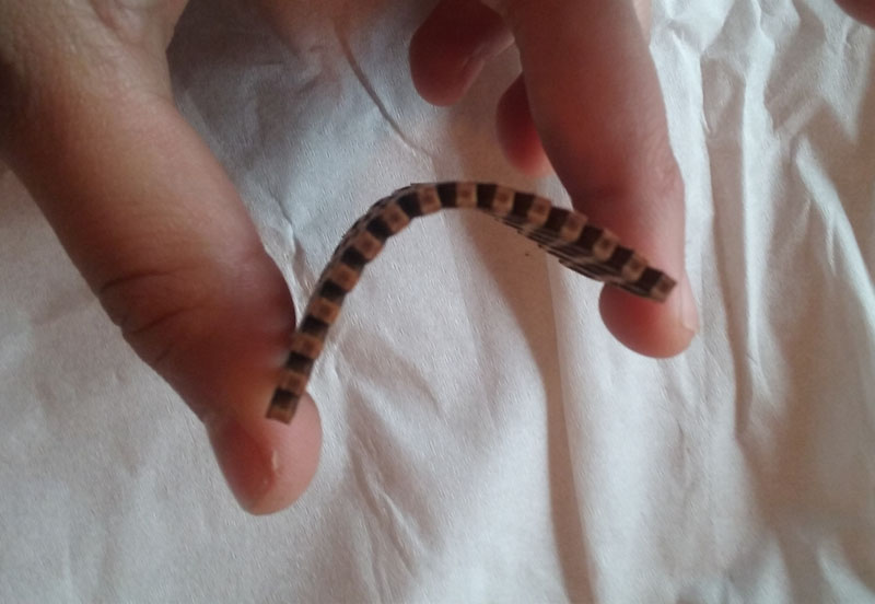
This week I have been also working on a test of the laser cut pattern I did for bending cardboard, but now applied to plywood.
I also used some patterns that Gorinicely shared to me.
And here the results:
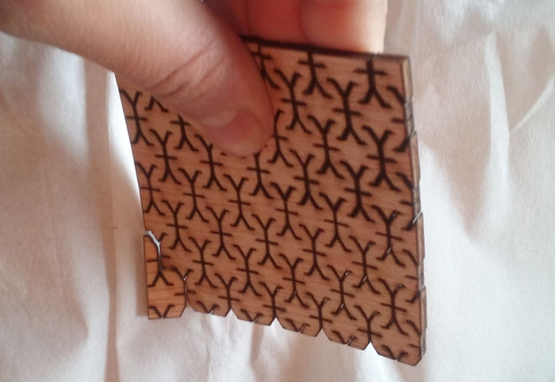
This is exactly the same pattern I used in cardboard. It seems not to work at all using 3 mm. plywood.
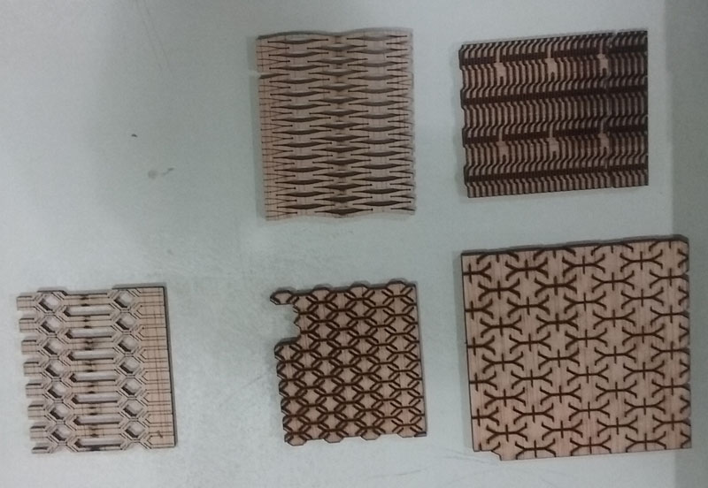
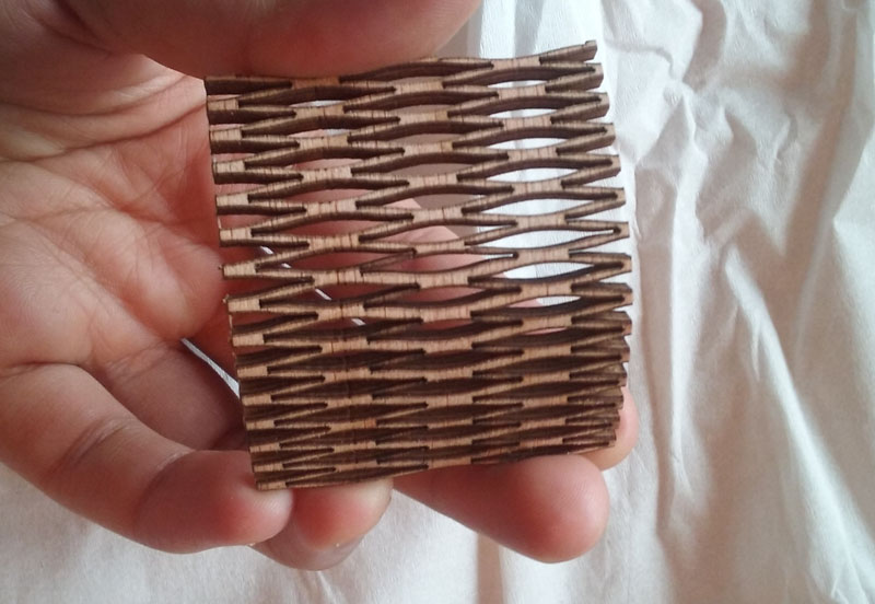
Good winner pattern.
Citlali Hernández - Fab Academy - 2016