hola soy un mensaje secreto wiwiwi wawawa
WEEK 13: OUTPUT DEVICES
Assignment:
| | | | | | | | | | | | | | | | | | | | | | | | | | | | | | | | | | | | | | | | | | | | | | | | | | | | | | | | | | | | | | | | | | | | | | | | | | | | | | | | | | | | | | | | | | | | | | | | | | | | | | | | | | | | | | | | | | | | | | | | | | | | | | | | |
// INFORMATION & RECOMMENDATIONS
-Read data sheets of your components and understand their function.
- Before copying Neil's boards, understand why every connection.
- Before milling your PCB, double or triple check your connections in your Eagle files.
- If you find a problem(s) during your assignment and found a solution, document it! I found several and couldn't find a well documented website.
I decided to work with the servo motor board, as I was thinking on probably using some as part of the ouputs I wanted for my final project.
About servomotors:
Rotary actuator or linear actuator that allows for precise control of angular or linear position, velocity and acceleration.
It consists of a suitable motor coupled to a sensor for position feedback. It also requires a relatively sophisticated controller, often a dedicated module designed specifically for use with servomotors.
| | | | | | | | | | | | | | | | | | | | | | | | | | | | | | | | | | | | | | | | | | | | | | | | | | | | | | | | | | | | | | | | | | | | | | | | | | | | | | | | | | | | | | | | | | | | | | | | | | | | | | | | | | | | | | | | | | | | | | | | | | | | | | | | |
VERSION 1
Making a PCB to control a servomotor-
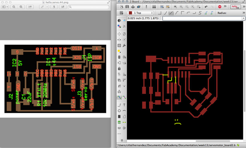
I followed Neil's design and just made a little tiny change design, just to keep on learning Eagle.
For milling the board, I followed the usual steps using the 1/32 milling bit for the outline, and 1/64 for the traces.
During that week Ferdi placed a nice whit stripe of LEDs in the Roland SRM 20, so I took the chance to record a video of the process:
Milling PCB for a servo motor.* from Citlali Limonada on Vimeo.
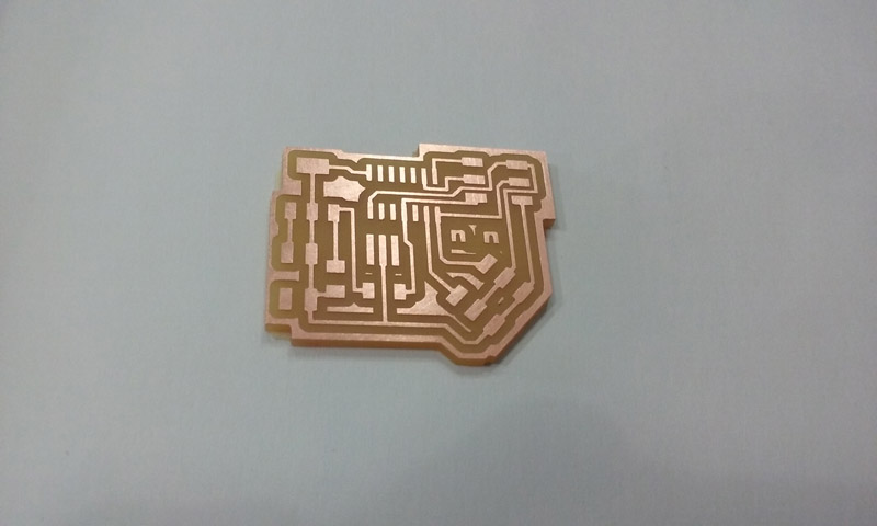
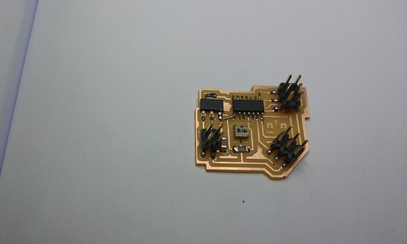
Milled board.
It looked nice, isn't it?
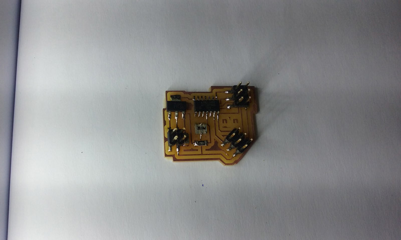
PCB soldered also looked beautiful.
Untill you look closely and discover that I forgot to connect 20 MHz crystal to the correspondant pins from the ATtiny44 and the output from the voltage regulator wasn't connected to VCC. Yey! COMBO MISTAKES!
FRANKEN SOLUTION!
I found out this problems because the board couldn't be recognized by FabISP programmer nor the AVR. I checked a lot of times to the connections with the multimeter, but then compared to Neil's design.
First I added a little piece of soldering wire between the voltage regulator and the VCC from ATtiny44.
Franken style solution no. 1
And then I added wires between the crystal and the PB2 and PB3 pins.
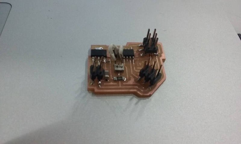
Franken style solution no. 2
And when I thought my board was ready to make some servos dance, AVR led was red and terminal + FabISP kept on throwing me ERROR #1.
:(
VERSION 2
After a couple of weeks I decided to take a look again into my board and understand why this was happening to me.
I looked into a lot a lot a lot of other's peoples output assignments and I found just a couple of succeeded ones. But it seemed that they were doing the same things that I did.
So I just blamed on my Franken solderings and repeated the board.
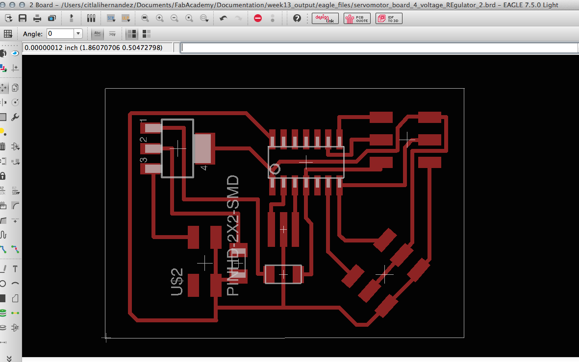
I went to Eagle, and connected what was missing.
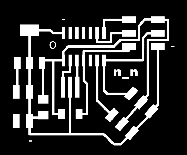
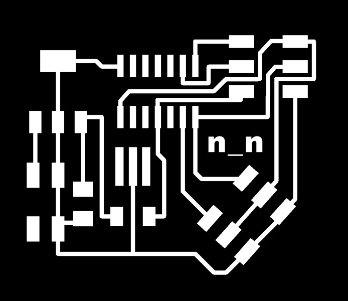
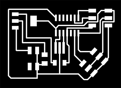
Traces
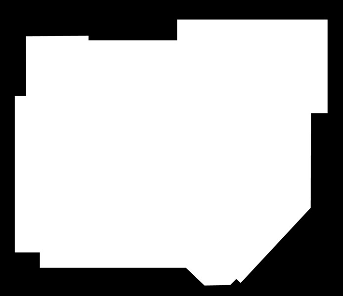
Outline
- So everything seemed to be perfect! But NO! NO! NO! NO! I even added the minus signs to recognize ground, and the "O" to place ATtiny in the good direction.
- But NO! I couldn't program ATtiny44 with Arduino, or with Neil's make files. :(
- I thought it was a good idea to ask Ferdi if we could find the mistake, we checked connections and everything "beeped" correctly.
- Then he suggested to check if the current was OK. And we found out that the voltage regulator was not throwing out 5V as it was supposed to do.
- Then we went to the Fab Inventory to double check that I had sodered the correct voltage regulator, and it seemed that yes!
- And when I was about to replace it thinking on that maybe my VR was just burned, Ferdi suggested to take a look on the datasheet of these SOT23.
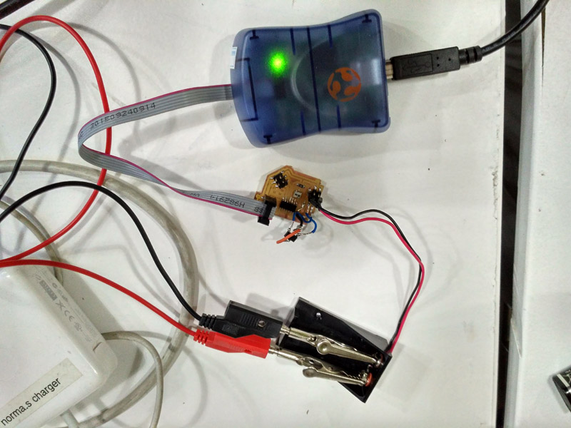
HURRAY!
- We found out that the SOT23 voltage regulator was not well connected.
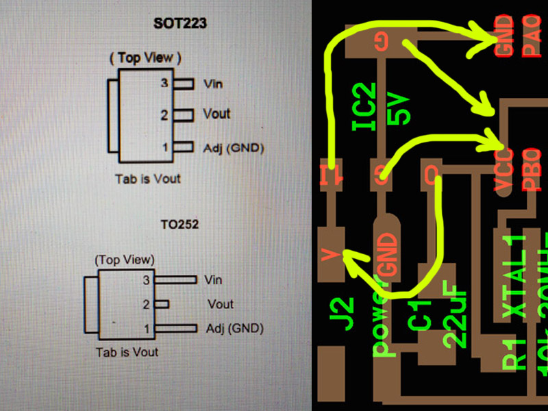
Connections should be like this.
So FRANKEN SOLUTIONS WERE BACK!
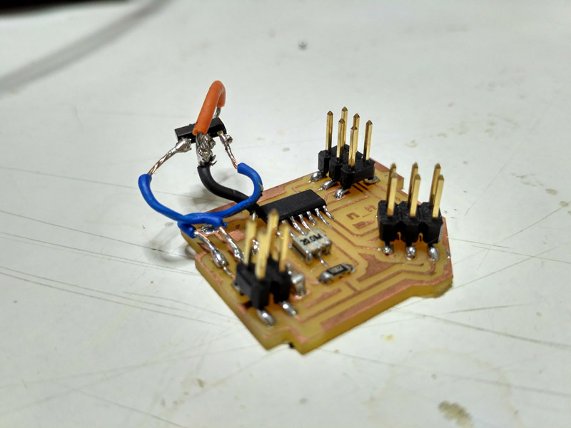
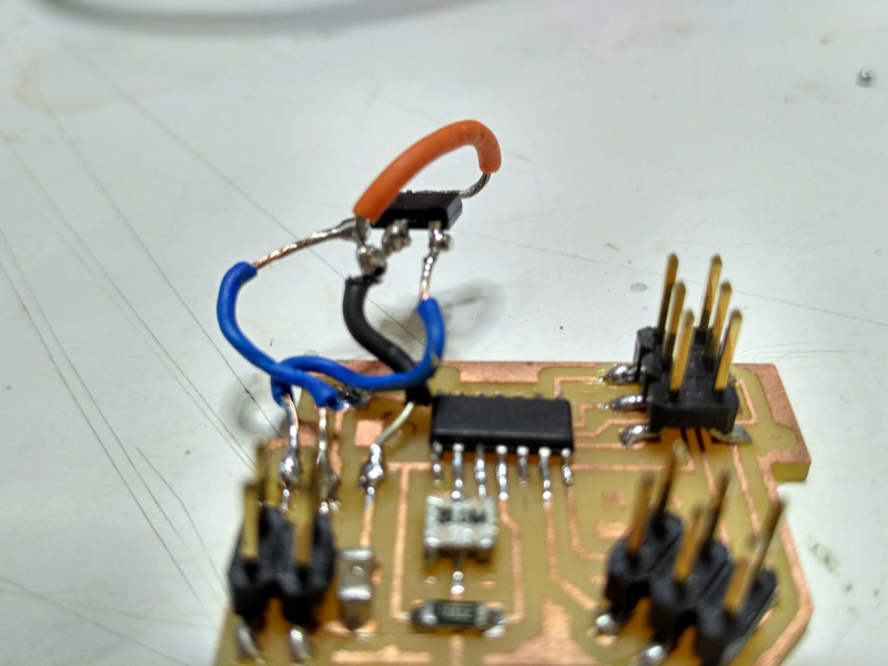
Look at this flying SOT23!
But finally AVR LED was green! So connections by far are good.
Unfortunatelly I tried to program ATtiny44, but Arduino throwed an error message like this:

Although I have a new fixed Eagle File and png's to mill, I hadn't had time to keep on trying with the FRANKEN version.
I couldn't make the test of my Franken solution. But you can download my new eagle files and try it! If it works please let me know.

| | | | | | | | | | | | | | | | | | | | | | | | | | | | | | | | | | | | | | | | | | | | | | | | | | | | | | | | | | | | | | | | | | | | | | | | | | | | | | | | | | | | | | | | | | | | | | | | | | | | | | | | | | | | | | | | | | | | | | | | | | | | | | | | |
>>FILES
1st corrected EAGLE FILES AND PNGS: You can download my 2nd version but it is wrong. :_(
FINAL VERSION EAGLE FILES AND PNGS: Give it a try! And if it works, please let me knoW!: DOWNLOAD
Citlali Hernández - Fab Academy - 2016