

The assignment for this week is building something furniture size with the Shopbot, a CNC router for wood like materials. The dimensions of the materials you can work with are maximum 2500x1250x100 mm. In this case I decided to build parts for my main project. The construction for the x and y axis in this case for managing the Beehive (Beesbot).
In the pricture below the construction of the x and y-axis is drawn in Solidworks.
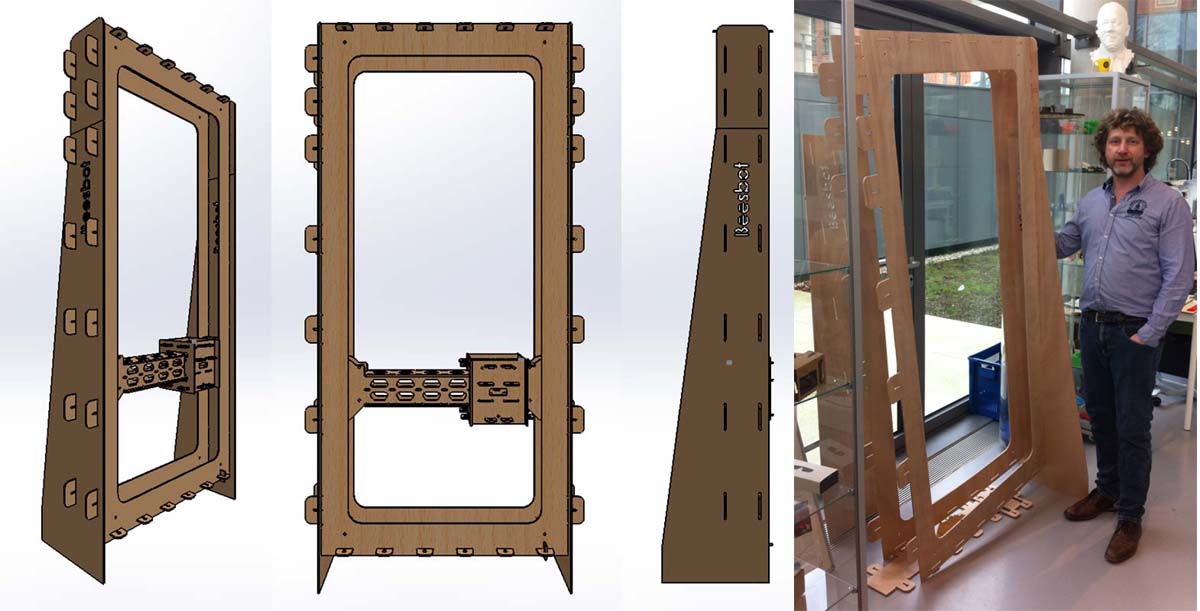
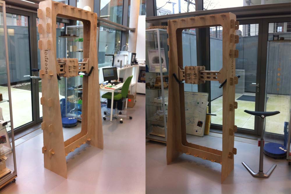
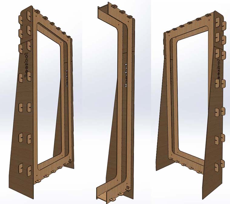
The construction is separated in two sub-assemblies. One for the x-axis and one for the y-axis.
Construction of the x-axis below.

Construction of the y-axis below.
In order to open the CAD part files in VCarve, I first made sure to export the Solidworks files to the dxf format so that the part file could be loaded onto the VCarve Software and have all toolpath information ready for me to configure.
I input the following settings within the 2D Profile Toolpath menu to generate the appropriate toolpath for each of the constituent parts of my model:
Cut Depth = 6.0mm
Tool = 6 mm down cut
No. of Passes = 2
Machine Vectors = Inside/Left
Direction = Climb
Allowance Offset = -0.1mm
Add Tabs to Toolpath --> Length = 6mm; Thickness = 5mm; Option Selected (ticked) = Create 3D Tabs
Within the "Edit Tool" submenu, the following settings were entered:
Spindle Speed = 15000 rpm
Feed Rate = 60.0 mm/sec
Plunge Rate = 10.0 mm/sec
The next steps were followed:
Now the file with the toolpaths (G-code) can be opened in the software of the Shopbot.
Below the simulation of the toolpaths in Vcarve is shown.
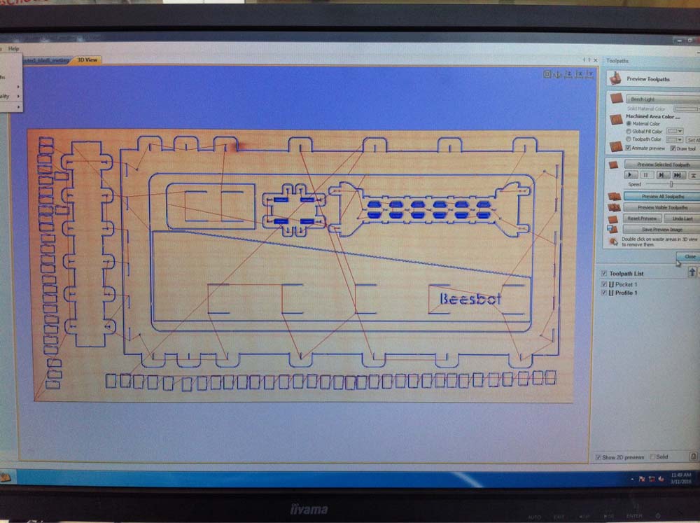
Below the dxf-files for milling the parts are shown.
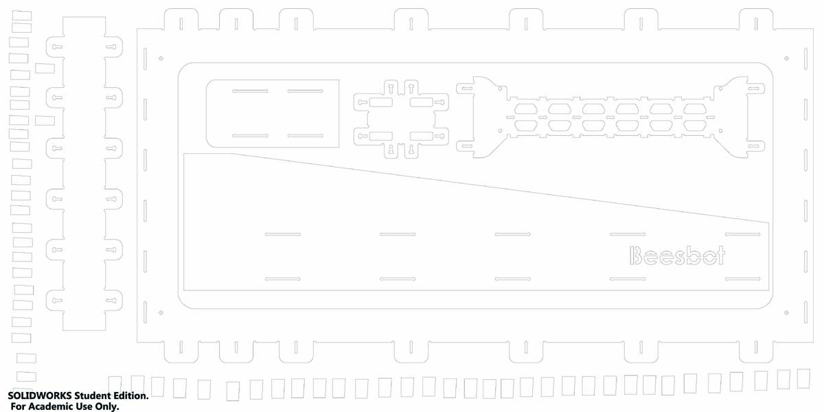

.

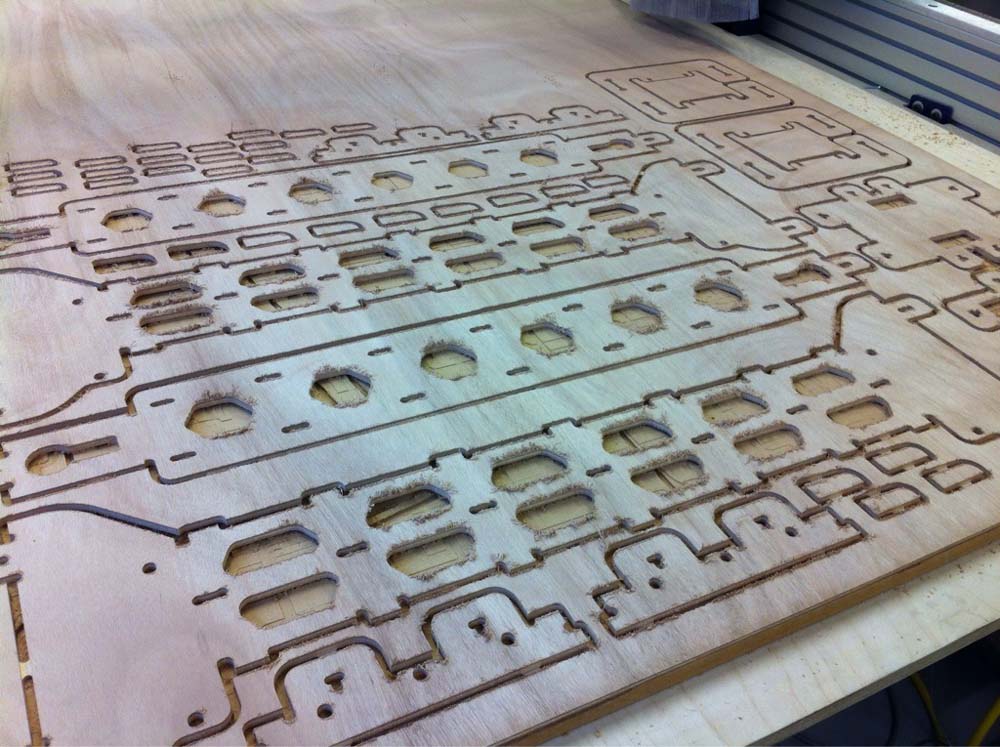
In the pictures below the willing process is shown and the result of the milling on the machine.
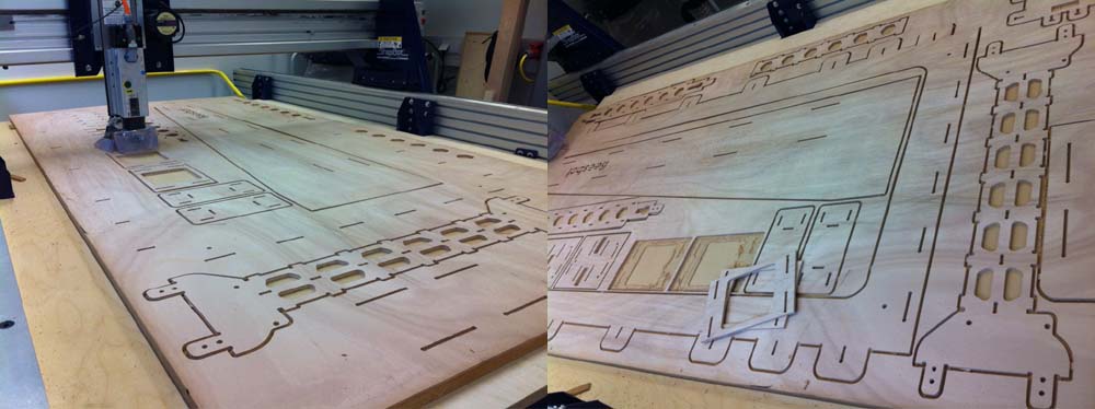
The construction for the Y-axis was easy to assemble.

Below the assembled construction of the x-axis is shown.
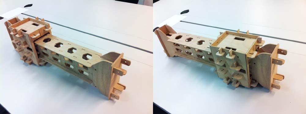
Because drawing of the parts in Solidworks was done very quickly there was a mistake in assembling the parts. One component could not slide over the other component. On the picture below on the left the problem is shown. In the picture in the middle the solution for this problem is shown, cutting the part open. Now it can be assembled.

One of the slot holes was not drawn in the right way, so this had to be reworked manually.

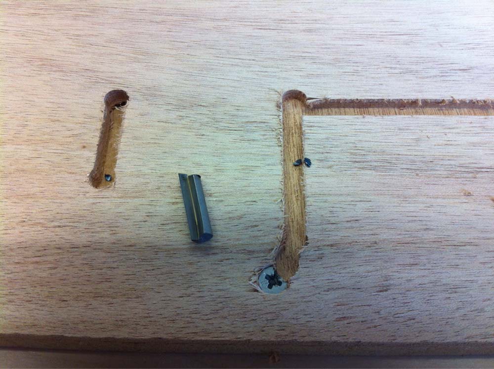
The parts were too close to the border of the wood. For this reason the mill came across the screw and the screw was stronger.... Next time more attention should be paid on the position of the parts and the screws.
It was mentioned earlier here. On default when loading the toolpaths in the software from the Shopbot you should deselect: XYDatum Position Use Offset. If you leave it selected the Shopbot will have problems with finding the origin. The machine will stop milling because it goes in the wrong direction. So unselect the Use offset. Now it will not have this problem.
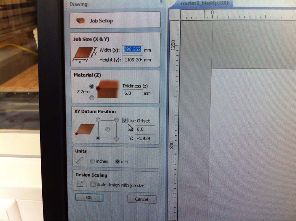
For unknown reasons the Z-axis was not going up high enough between milling jobs (parts). This resulted in damaged parts (wood). Next time more attention should be paid to the simulation of the milling. Not all parts are like this, this makes it hard to understand and strange.
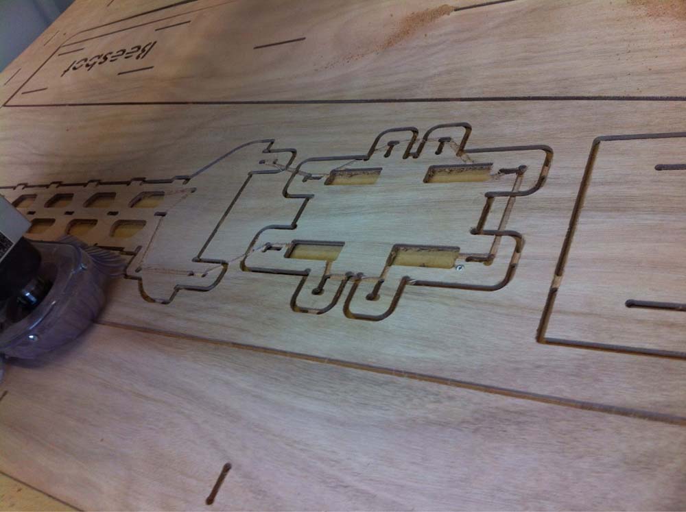
The material that is used here is 6 mm thick. First I made all drawings with slot cuts of 6 mm wide. Later I noticed we have an 1/4th inch mill (6.35 mm). For this reason all slots were changed to 6.4 mm but I forgot a few of them, they were still on 6 mm. The software for generating the toolpaths decides not to go into pockets smaller than the diameter of the mill. This should also be visible in the simulation. So more attention should be paid there ( I was in a hurry).
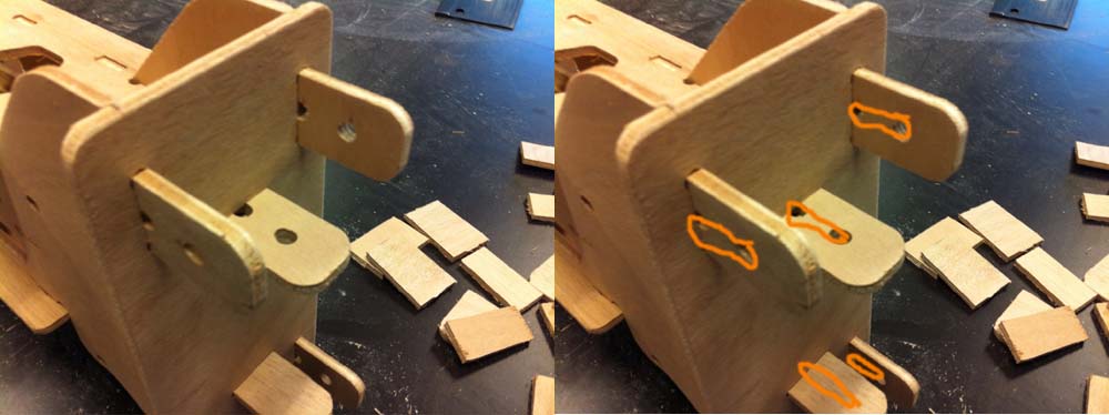
The above mentioned problems were solvable and I still had some milling time. The joining elements were too big in my opinion so I changed the size to 10 mm smaller.
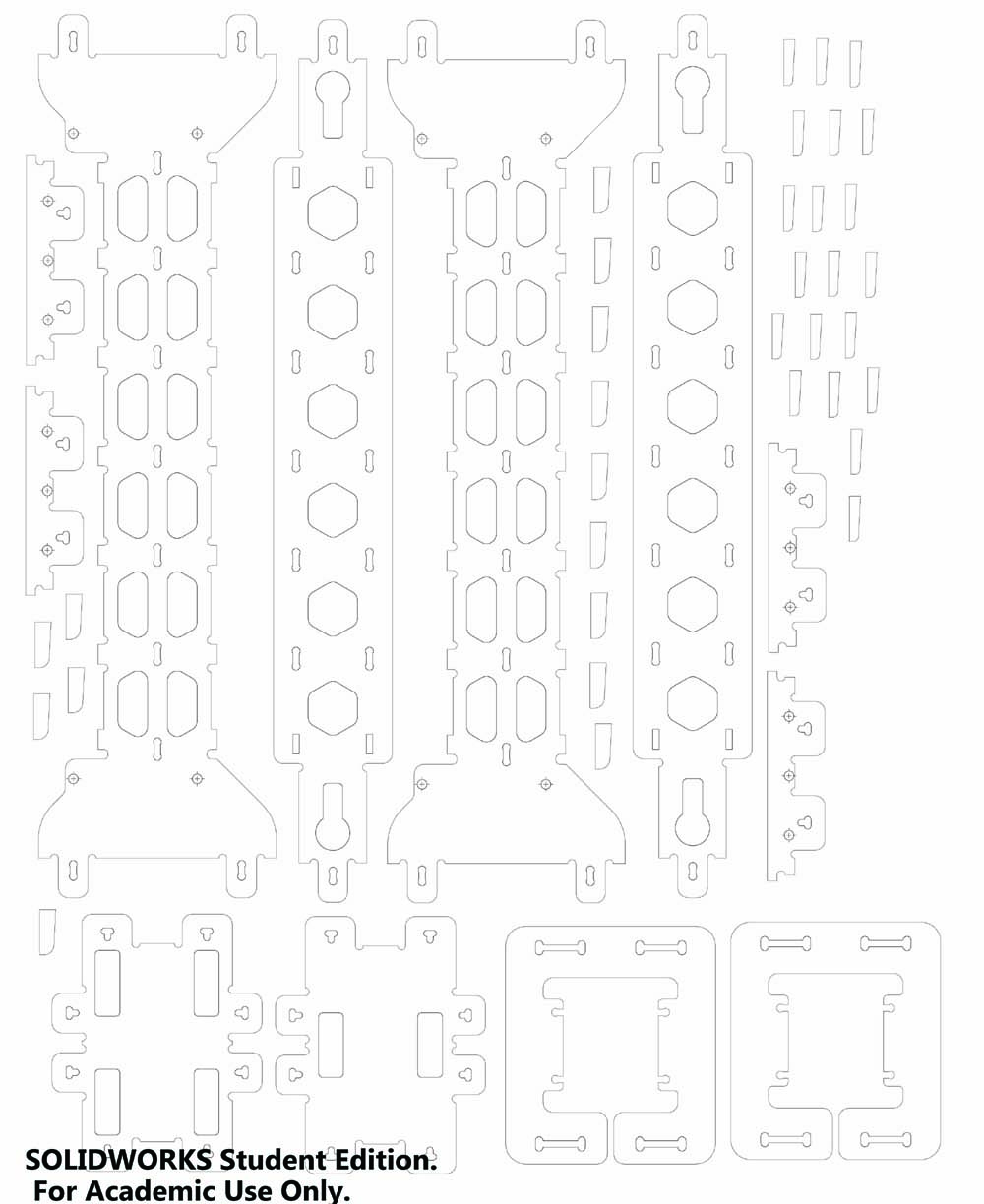
The picture below is the new version with the modifications in it.

The milling of the last part was more difficult because the mill was not very sharp. This resulted in a rough cut and more sound from the milling process. Later I noticed that also the dimension of similar parts that were milled before were now a little bit bigger. I think this is the result of the dull mill.
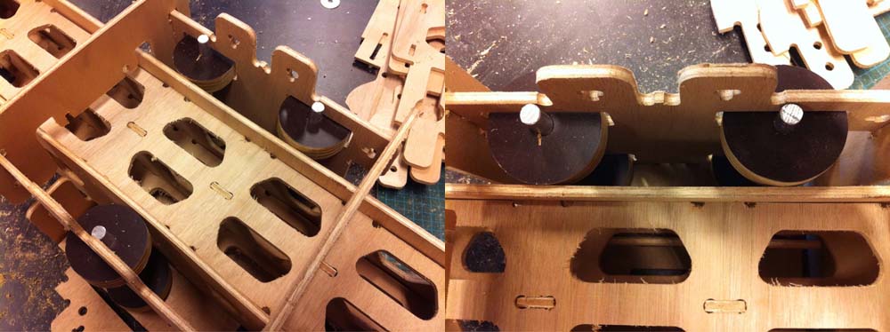
The wheels were milled out of 18 mm plywood. Aluminum axis were made to assemble the wheels.
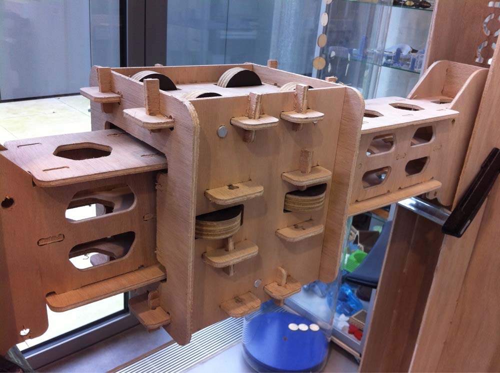
The picture below shows the complete X-axis. With wax and butter the wheels are running smooth now.
From Github: Files for xy-frame.. Click "view raw" to download.
Please go ahead and use my files to modify it to something for your need. All files for making the xy-frame.