

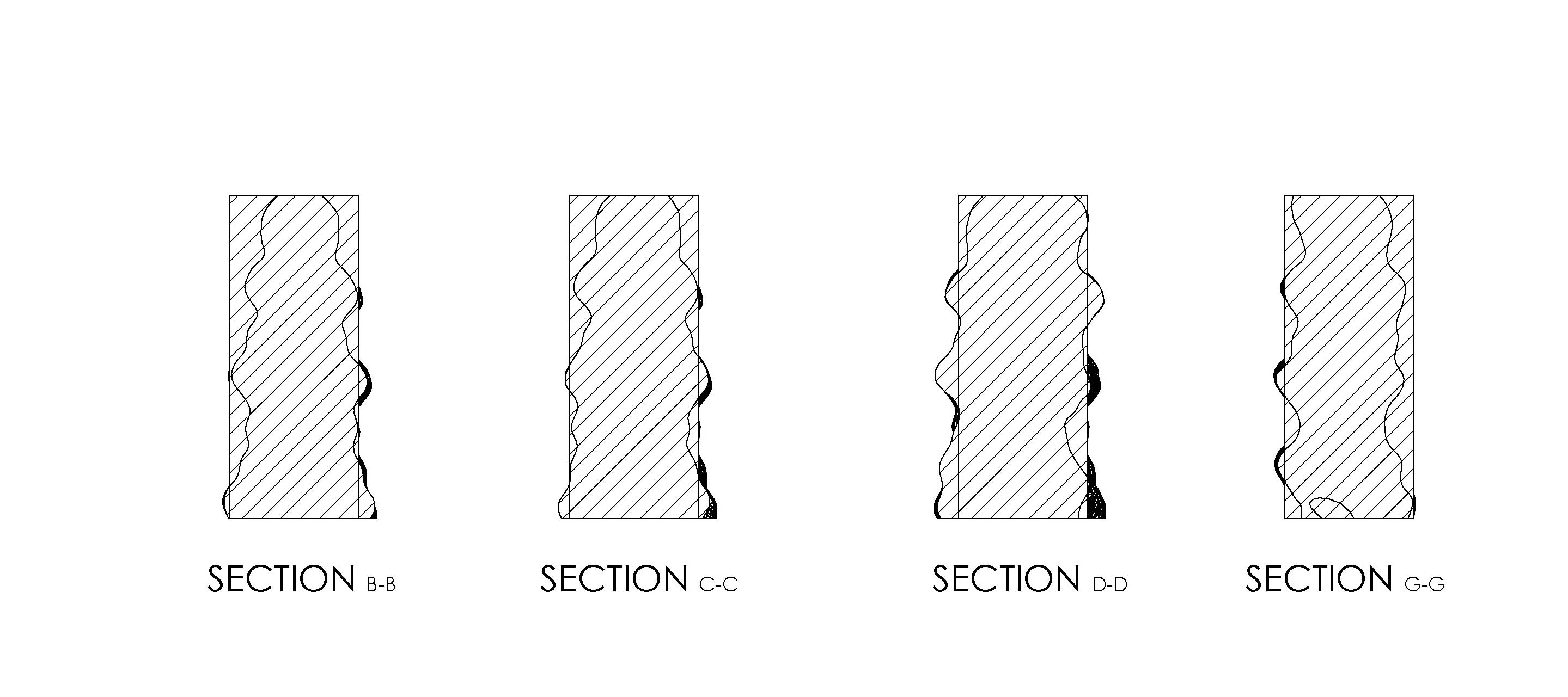
Hello readers of my elaboration of week five. This week there are three subjects (1) 3D scanning of objects, (2) 3D printing of an object that is difficult to shape because of undercuts, and (3) thinking about design rules in 3D printing. For the first topic, scan a 3D object, I use a project where students of mine work on. A 3d-concrete printer is developed by Saxion LED students. I'm one of the tutors of this group. The 3d concrete printer is on a laboratory scale and can print objects in concrete. Now one of the objectives of this group is to print and measure reproducibility. In this case reproducible means that if the same form is printed multiple times, the difference between these forms is minimal and controllable. To measure this, I want to figure out whether a 3D scanner can provide a solution. The designed original CAD file is then compared with the 3D scan of the product. This can be compared in two ways (a) with 2d cross sections (a) or (b) with 3D volumes. With the first mentioned method the difference between the sections can be analyzed by comparing the cross sections. In the second method the volumes of the differences are quantified. This test can be carried out on 10 identical printed parts, and the result will be an overview of deviations from the original digital design. The following illustrations show the different steps, and what can be measured on a 2D and 3D method. The images show the cross-sectional view of a concrete object to be printed. On the far left is shown the CAD object. There is next to the division of the different print layers where the G-codes are generated. The third image shows where the product is depositioned in printing. Now, there are two differences. (i) there is something too little material and (ii) there is somewhere too much material. In the picture below the 3d concrete printer is displayed.

Imagine you want to check the quality of the geometrical shape from a peace of a 3d-printed concrete wall as shown in the picture below (wall from a Chinese 3d concrete printer in this case).

The piece that was scanned below is a broken out section from a printed wall like in the picture above.
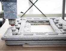
The picture below shows one of the prints from our lab scale concrete printer.
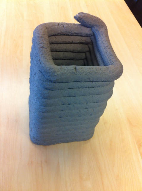
With the Sens 3D scanner a small concrete object is scanned. The dimensions of the concrete parts are roughly 25 cm by 10 cm and 10 cm high. The thickness is approximately 3 cm. Six layers are printed in concrete The Sens scanner gives as output file an STL file. The original shape is drawn in SolidWorks. An STL file can be opened in the new version of SolidWorks as a solid form, so that it can be used to extract from another body. Unfortunately, there is a limitation of the complexity of the model, the maximum is 20,000 triangles. The scan of the relatively small object does have more than 100,000 triangular faces, so there is a problem. The reduction of the number of triangles is a possibility, but you actually don’t want to, because it does not benefit the accuracy of the measurement.
The piece of concrete was placed on a table. With the Sence scanner it was scanned all around. In the software you can pre select the estimated size of the object. Try different versions to see the differences. After scanning the software drives you through some options to make a nice and clean solid STL-file.
The scanning was done similar to the video below.

Fortunately, Rhino offers a solution whereby the stl file can be opened with a large number of triangular surfaces. If necessary, you can reduce the number of triangles in Rhino. Then, the stl-mesh should be converted to a NURB-mesh. In this way, it becomes possible to divide the file into smaller pieces. Smaller pieces can be exported as a step file, with the origin exported as well, the parts can be assembled using the same origin. SolidWorks individual step-files can be imported and then the parts are stored as a SolidWorks file. Now it is possible to place more solid work files together into one part (this may sound strange, but it works). This new part then has multiple bodies. The bodies of the STL-scans from Rhino can be compared to the original shape of the concrete design. Now it is possible to analyse the different shapes on a 2D method (on a 2d drawing) and a 3D method.




Here you can download the files from the scan and Solidworks.
In this case I decide to design and make a bottle and lid with a complex inner and outer shape. The video below explains why it is difficult to make this bottle in a conventional method. With 3d printing there are no big problems to make these shapes.
The inside of the bottle has a large undercut all around. Also, the exterior of the bottle has undercuts. For the bottle cap it is the same. On the inside there are hooks and the outside is a form similar to the bottle. In this assignment, I want to show that the bottle and cap can be properly printed. I would also show how the form might be cast in a conventional manner. Why would I want to mould a bottle? My project is about keeping bees and harvesting honey. Now the bees in the beehive already packed the honey in honeycomb made from beeswax. This is useful for bees, but for people not yet optimal. The honey and the wax can be separated from each other. This makes it possible to use the beeswax to mould new bottles for the honey. In this way, the packaging of the honey is super eco-friendly.


The first print that was made from a bottle with cap was about 50 mm high. This proved to be very large for doing all different tests. For this reason, the new print is made on a 50% scale. This turned out enormously small. Afterwards it made sense because the factor 2 works in three directions, making the mass 8 times smaller.


After the 50% print, it was decided to continue with prints of 75%. The focus has shifted from making the bottle to how to design the mold and how it can be printed. The inner core is divided into a central pin which can be pulled away and a ring which is built out of removable segments.
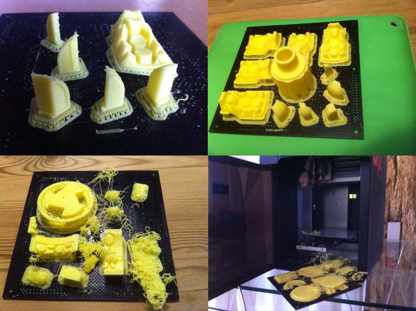
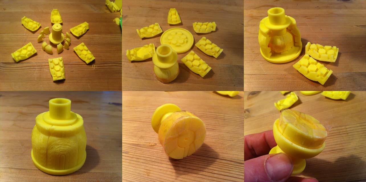
The assembling of the segments is difficult, to improve this a separate tool was printed for holding the little pieces in place. The outside of the bottle is shaped by six slides from the outside and the bottom is formed by the lower mould.

The cap is made on the inside by the core of the mold and three releasable lifters. In this manner, the hooks can be formed for the closure. The exterior is formed by three sliders. The top is formed by the upper mold.
In our Fablab in Enschede there are many examples available from the UP 3d printer in PLA. These examples were studied and below you will find the information.
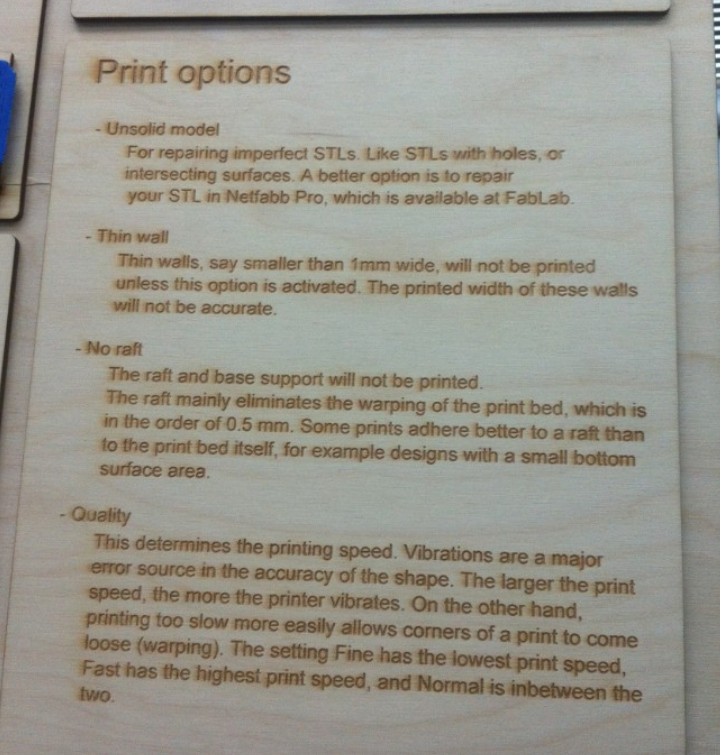
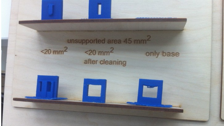
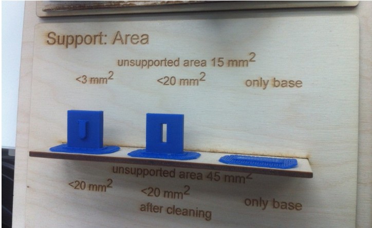

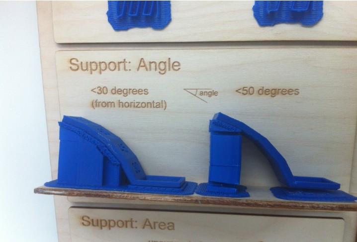
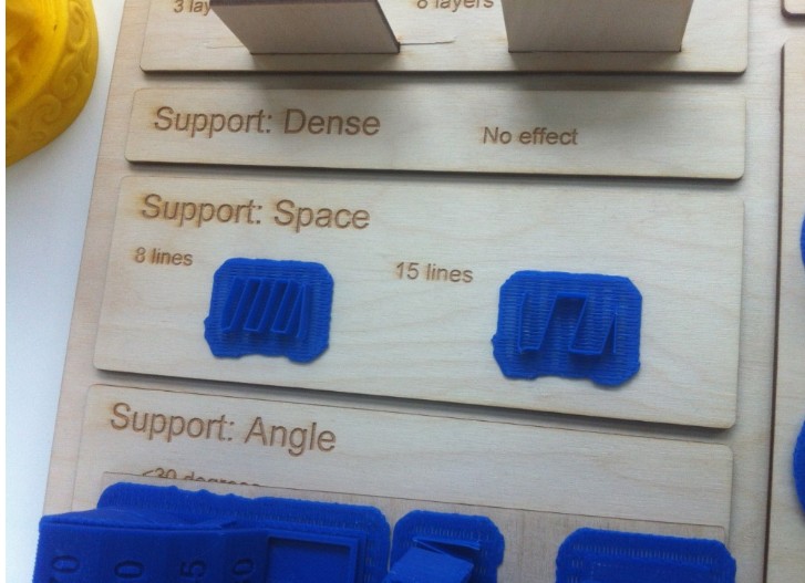
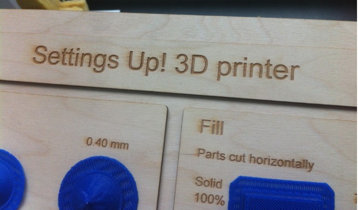
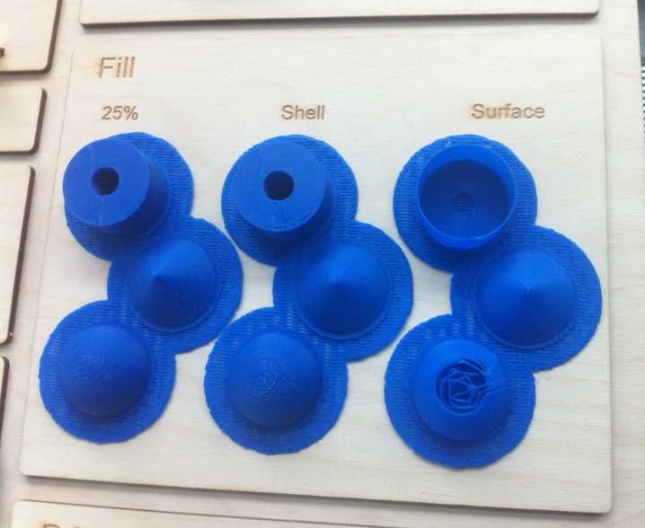
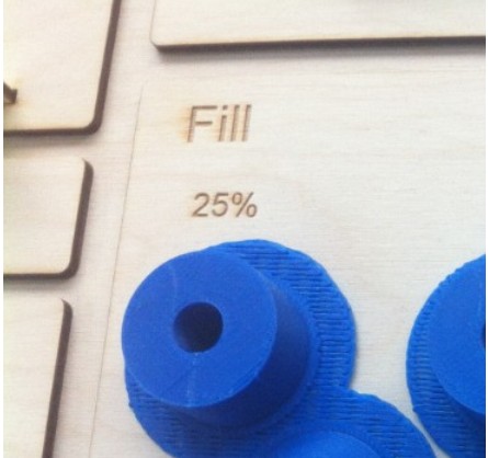
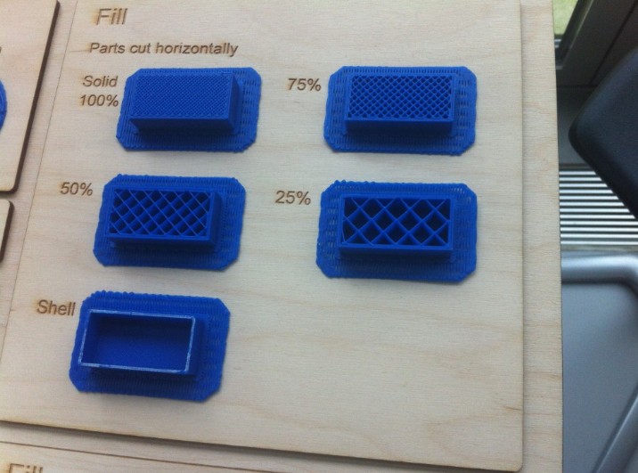
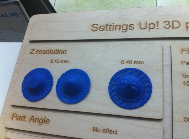
On the website from Shapeways you can find much information on design rules for different 3d print processes. In this case I looked for information on printing with PLA.


For my 3d-prints I used the UP mini a lot. Design guidlines are listed here in this document.
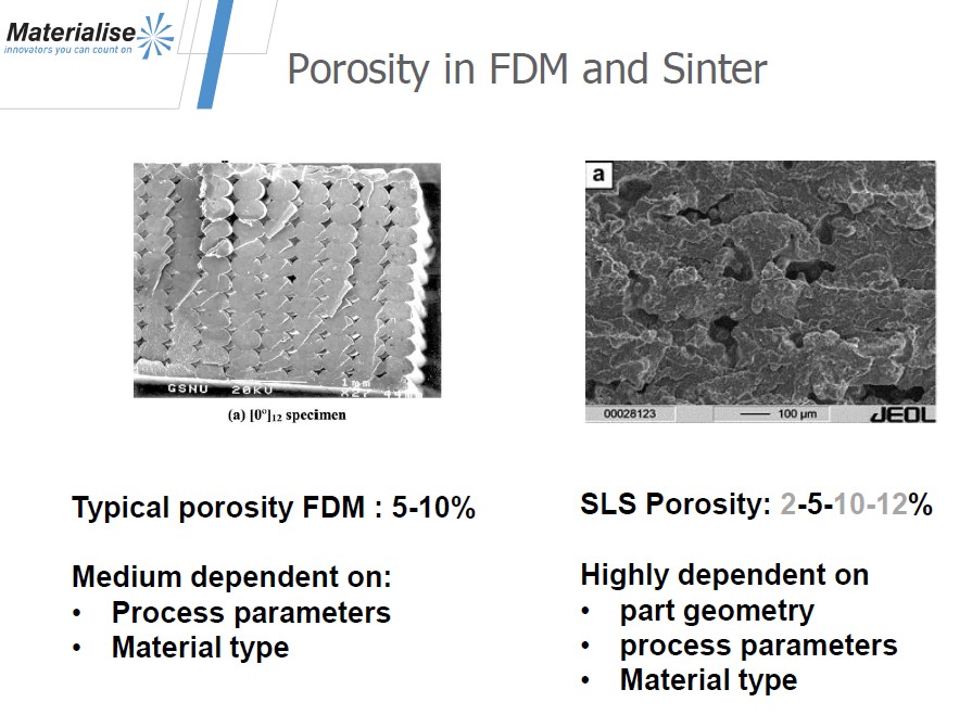
A good scource for guidelines from different 3d printing processes and materials is the website from Shapeways. One of the biggest problems in the case of printing the bottle with an FDM process or a Sinter process is that the material structure will be porous, even with professional machines and materials. The picture below is from the company Materialise. They have professional machines for SLS and FDM. An alternative for making solid shapes is the SLA, DLP or Objet method.
From Github: Beeswax honeypot plus 3d printed mold for casting.. Click "view raw" to download.