

For this week about computer controlled cutting I will work in two directions. (1) Exploring different joining shapes between perpendicular pieces of cardboard. In a rectangular shaped box with a lid I tried as many different joining shapes as possible and (2) Using the Sheet Metal function from Solidworks in this case for 3 mm cardboard. Instead of joining two or more pieces perpendicular bending the corner has great benefits.
Way of work in the joining shapes: For modelling the box with joining shapes I like to work in Solidworks in one part. There I can make multiple bodies. This way it is possible to design all the pieces you need just in one part quickly. You have to know the concept of how to merge or not to merge when creating new features in Solidworks. When the part is complete (all bodies needed) it is possible to convert each body into a new part. After saving all parts can be assembled in the main assembly. It is recommended to assemble the first design part with all the original bodies as well. This way you will not lose the original information. When assembling the parts use the origin to align each part. All parts are on the right place automatically. For laser cutting make a new drawing and assemble all the views from the parts on a page. Save as a dxf file and it is ready for cutting.
The 3d viewer below shows the model of a cardboard box with many joining shapes.
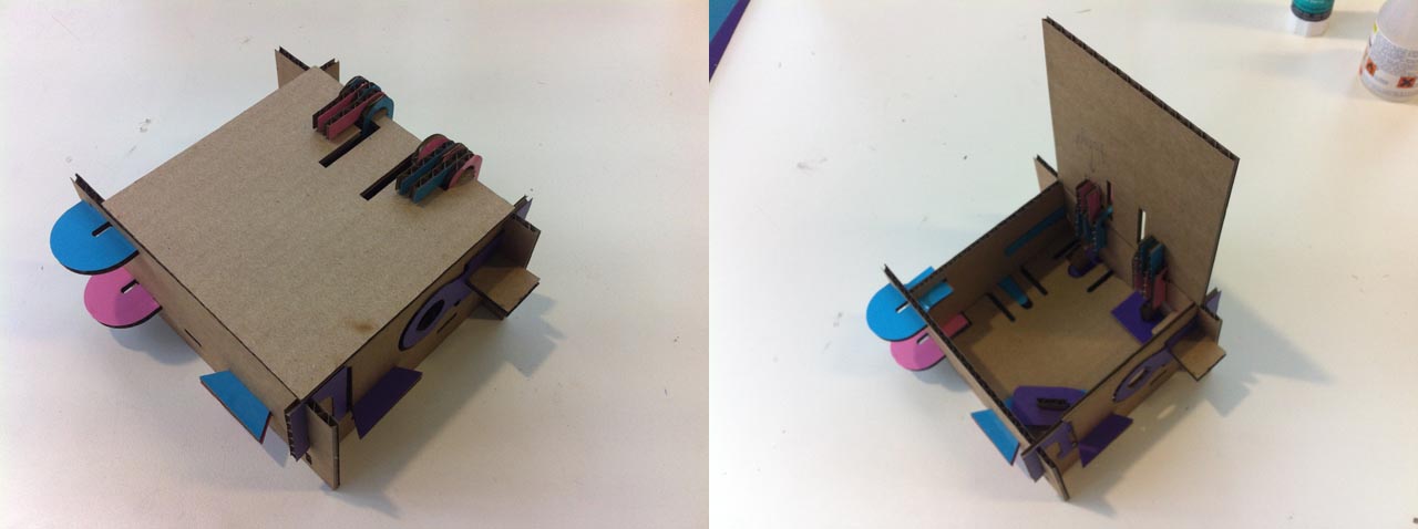
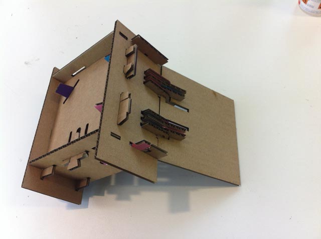
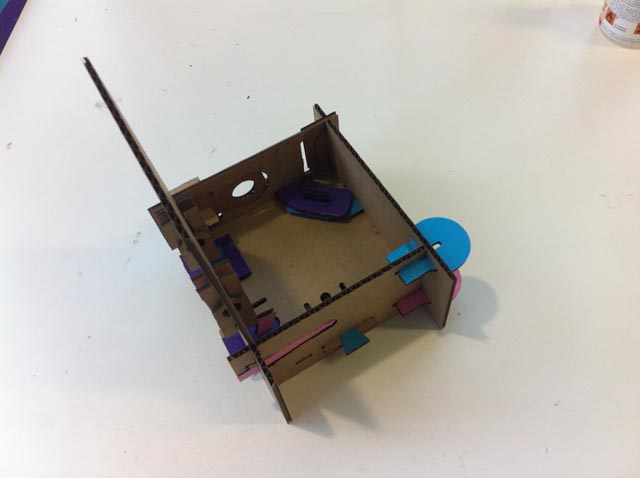
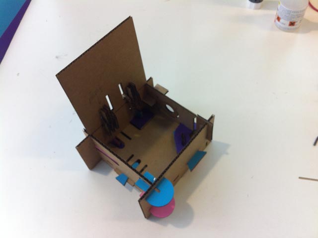
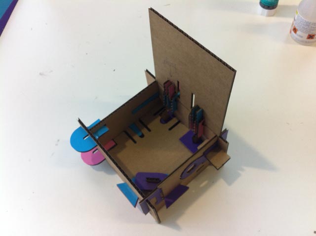
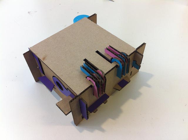
The picture below shows the cardboard box with all joining shapes in an open and closed position.
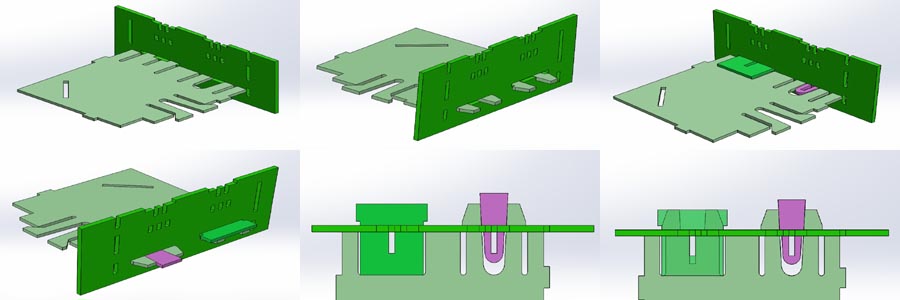
The picture below shows the Solidworks model from different perspectives so the joining shapes are visible in an overview.

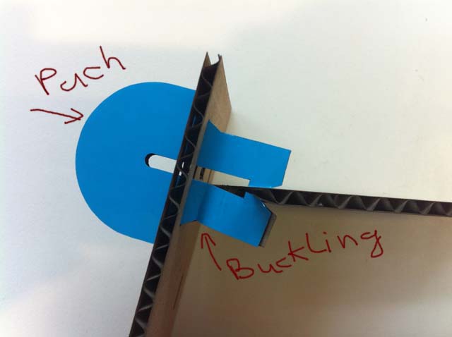
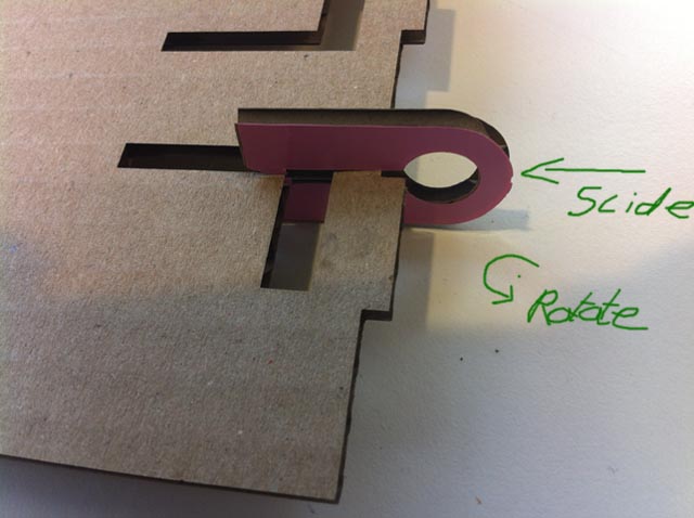
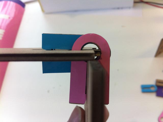
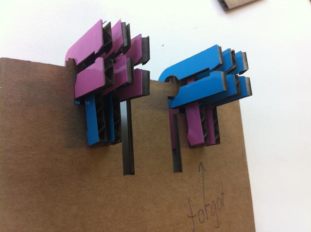
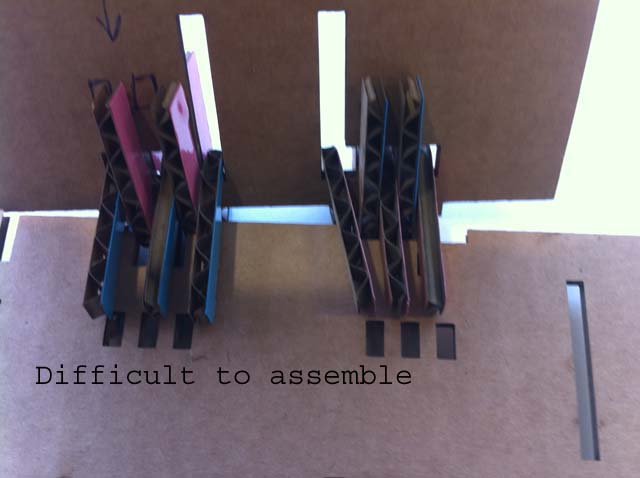
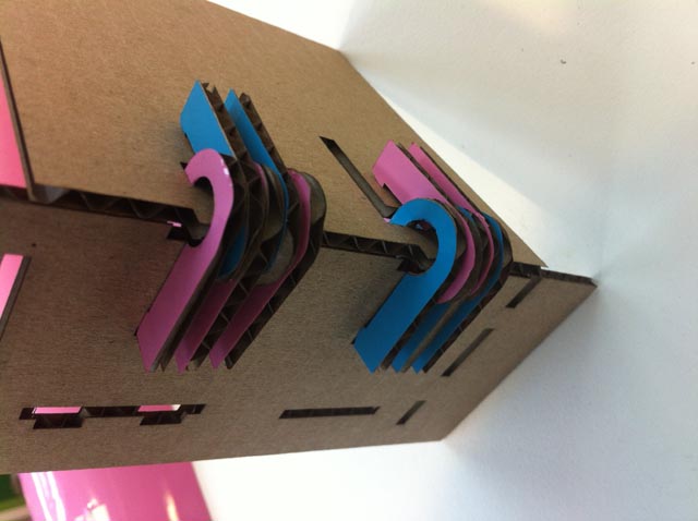
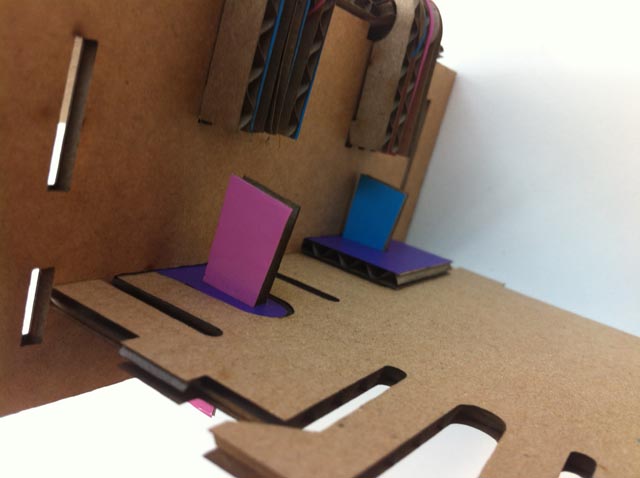
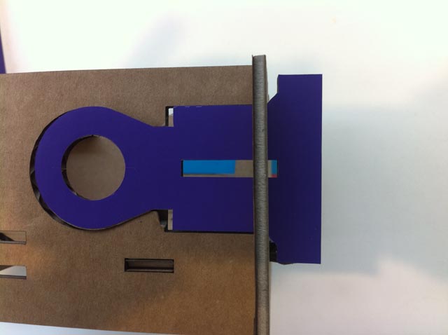
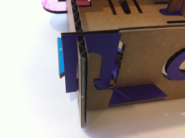
In the picture below the different joining shapes between two walls are shown. The additional parts will block the click fingers from coming lose.
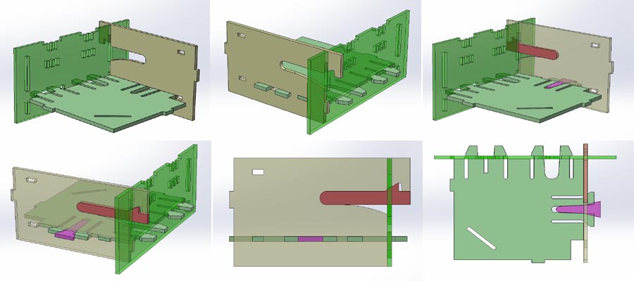
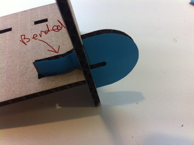
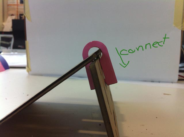
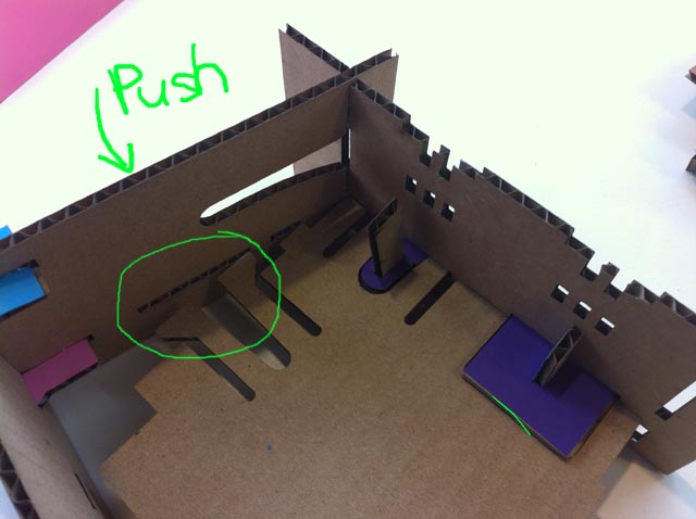
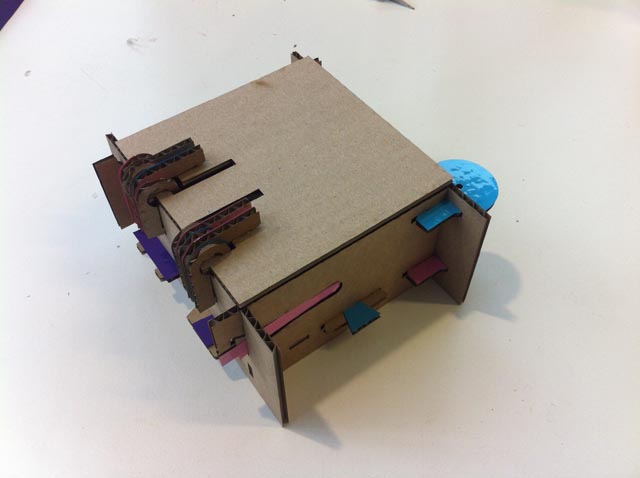
The second side wall with different joining shapes. The big circle part has to bend out to make assembling possible.

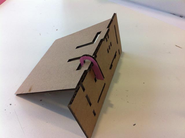
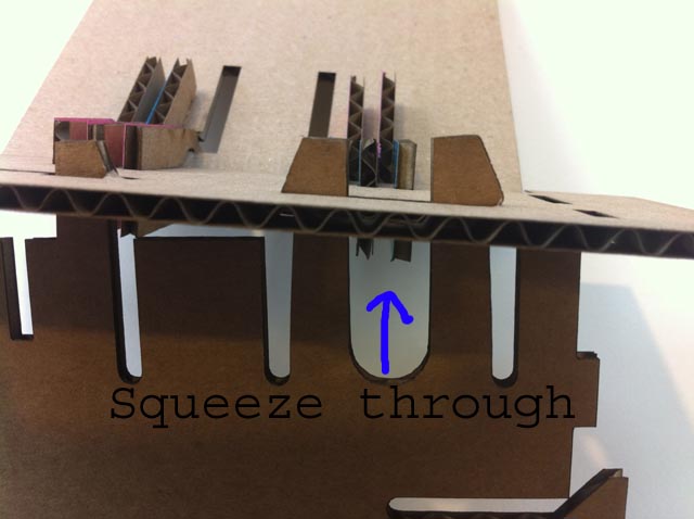
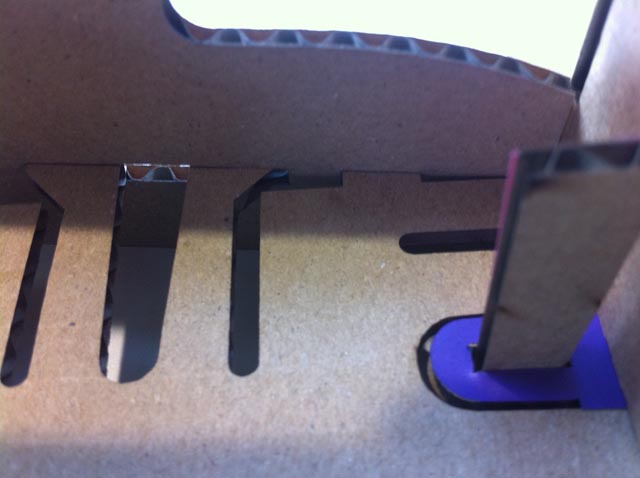
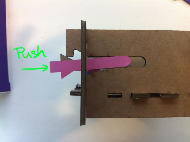
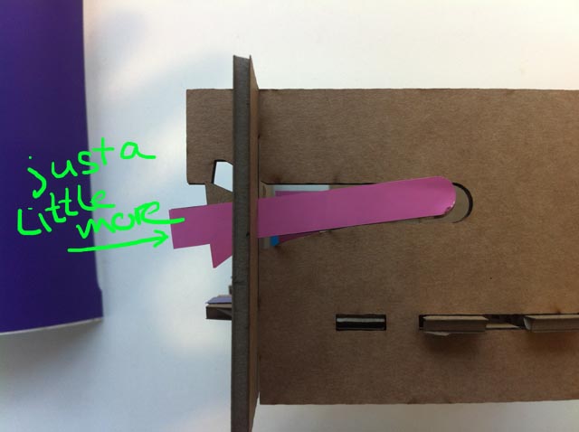
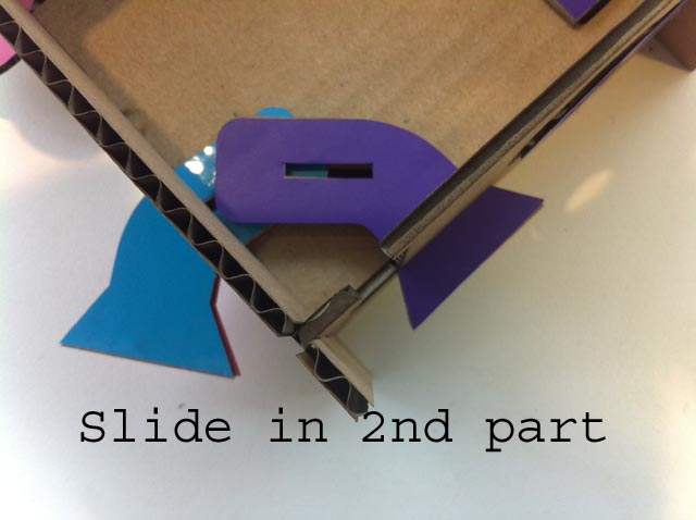
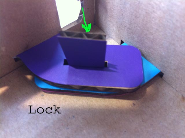
The third wall is assembled with two additional parts. One part is squeezing the clickfingers outward. The other part is the click finger it self.
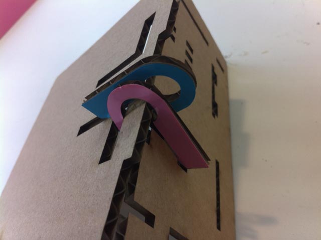
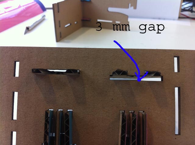
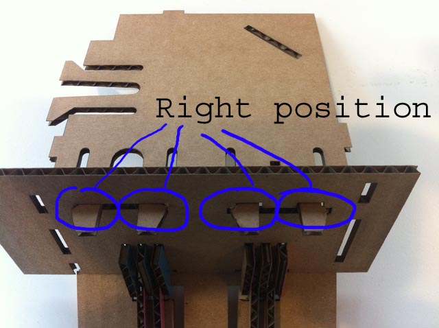
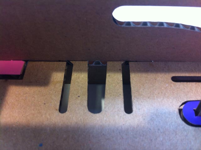
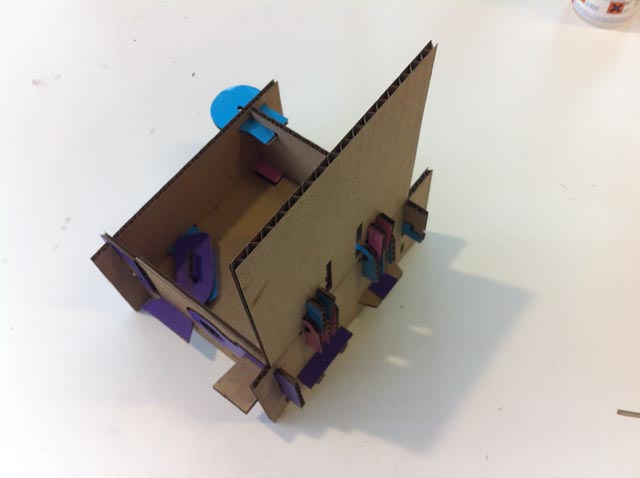
The next wall is again assembled with different shapes. On the right side a wedge is pulling the parts inward.
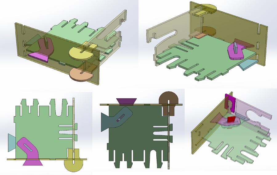
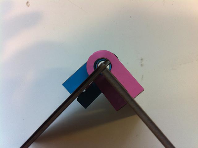
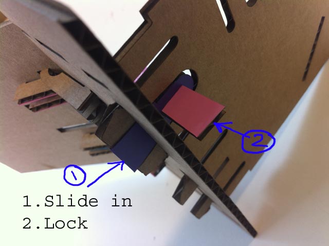
The next joining shape below.
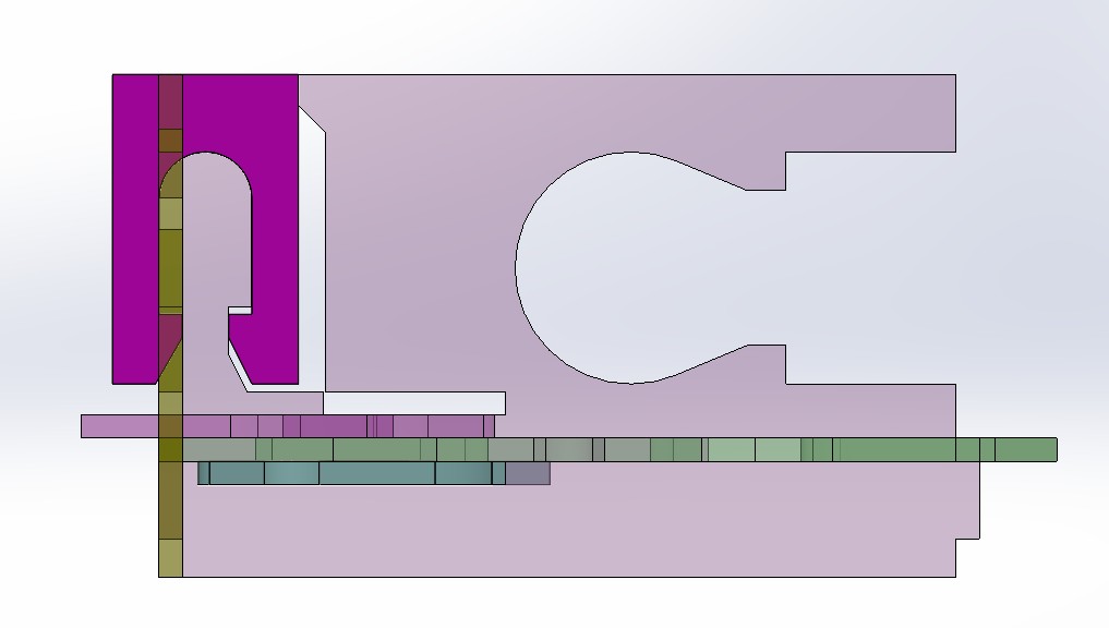
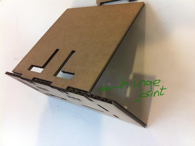
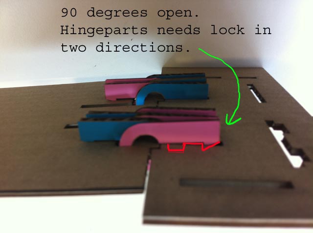
The lid of the cube is assembled with parts that make a hinge.

Some of the cardboard parst are produced on the big lasercutter in the Waag. There I used the settings below:

On the Trotec lasercutters it is just a matter of selecting the right material into the print software.
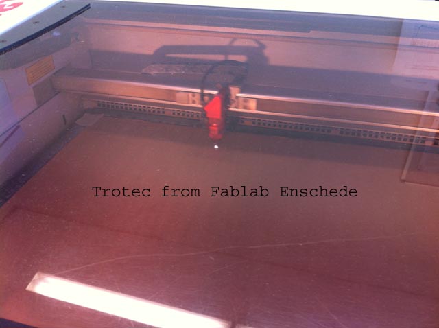
In our university and Fablab in Enschede we have two Trotec laser cutters. One uses Correldraw and the other one uses Illustrator for the preprocessing of the files. Basically the function of these software is the same. In this case I use Solidworks to create the 3d-parts. These parts are added to a 2d drawing in Solidworks. This can be exported as dxf- files. Correlated and Illustrator can open these dxf-files. With this software the line thickness and colour must change to specific values. Red for the colour and 0,01 mm for the line thickness.With Illustrator it is possible to define the order of cutting. When you want to make accurate cuts, it is often better to cut the holes first and than the contour of each part.
When exporting the modified file to the print software the material can be selected with the specific values for cutting.
To give the different joining parts I decided to use the foil cutter with different foil colours. Also here the original shapes for cutting were defined in Solidworks. From 3d parts a 2d drawing was made and exported as a dxf-file. This dxf-file was the input

In our Fablab we use a GCC Puma III 60 foil cutter. The maximum width of the cutter is 60 cm (580 mm cutting with). Many different colors are available in xxx. The foil thickness is about 30 micron. Also thin copper foil can be cut on this machine. The Software is called Easysign and it is easy to use. It works with file formats like ai (versie 8), svg, cdr, dxf and dwg. Non vector formats, like a bitmap, first need to be processed to for instance Illustrator to create a vector file. In this case I use a dxf file directly from Solidworks.
The smallest radius for cutting is about 0.25 mm. Many small details close to each other can cause problems with cutting. The picture below shows the dxf file generated from Solidworks, which was used for cutting the foil.
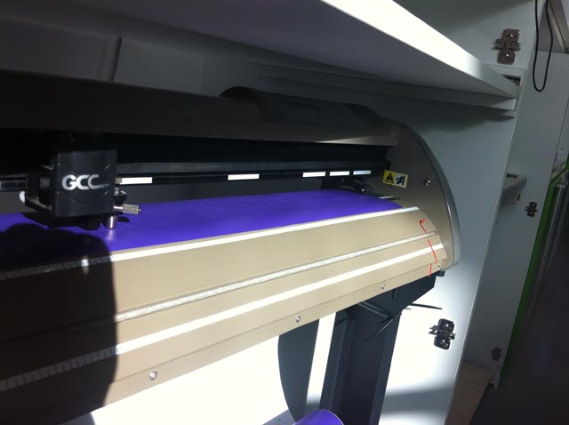
This is the manual for using the foil cutter.
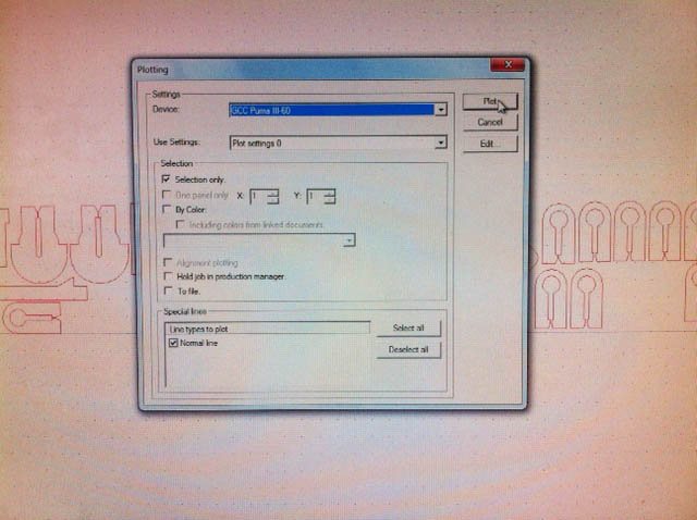
In the different pictures below it is explained how the dxf-file, that originally is made in Solidworks, is imported into the software from the folicutter. You have to play with the zoom function to find the design on the screen.

Command plotting.
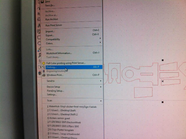
Command plot.
 |
 |
 |
 |
 |
 |
 |
 |
 |
 |
 |
 |
 |
 |
 |
 |
 |
 |
 |
 |
 |
 |
 |
 |
 |
 |
 |
 |
 |
 |
 |
 |
 |
 |
 |
 |
 |
 |
 |
 |
 |
 |
 |
 |
 |
 |
 |
 |
 |
 |
 |
 |
 |
 |
Way of work in the Solidworks Sheet Cardboard module: The Sheet Metal module from Solidworks lets the designer work in two ways. (1) start from scratch in Sheet Metal, this way you design from thinking in sheet material. Personally I prefer (2) design the shape that you need, cut the shape open so it can be unfolded and start the Sheet Metal function at the end of a part. Both methods work, I just prefer the second method. The important difference between steel and cardboard in this case is the strain allowed in the material before it breaks. Ordinary steel can have much strain before it breaks. Cardboard unfortunately will break much easier with a little strain. Also the thickness of the cardboard is much bigger compared to the most used sheet metal (3 - 1 mm). The bigger thickness also results in a larger strain when bending. The Sheet Metal module in Solidworks automatically calculates the compensation from each bend (great function). But in Cardboard this is not necessary. The solution I use here is reducing the bending radius to 0.1 mm. The centre line of each bend will be shown on the unfolded parts for cutting. The bend lines can be cut with a dotted line right through the cardboard. After laser cutting the outer corner can be cutted open with a knife. Be careful not to cut too deep. To explain this method more in detail in Solidworks please check this tutorial (in Dutch :( with many) pictures). Conclusions on the two different directions: (1) Many possibilities for joiningshapes. A few of them are good for cliff hanging, others are too week. The behaviour of cardboard is much different compared to solid materials, but the basic principles can be tested like this. (2) Using the SheetCardboard module in Solidworks is very efficient.
Below picture shows the cardboard folded segment from a beehive and two frames for inside the beehive.


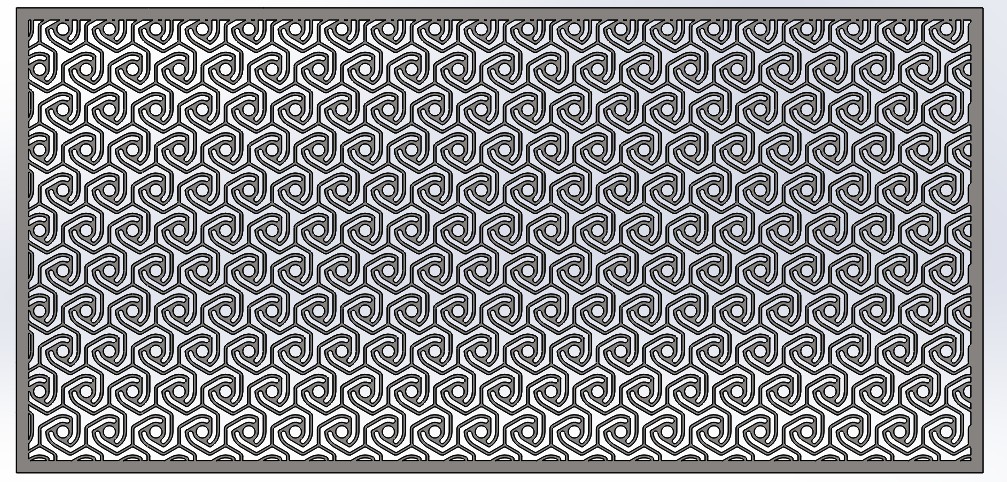
The pattern below was modelled in Solidworks and cut out of a sheet of thin paper with a print from a beehive frame. This cutout follows a honeycomb shape and makes the pater bendable in all directions. The file is shared below.
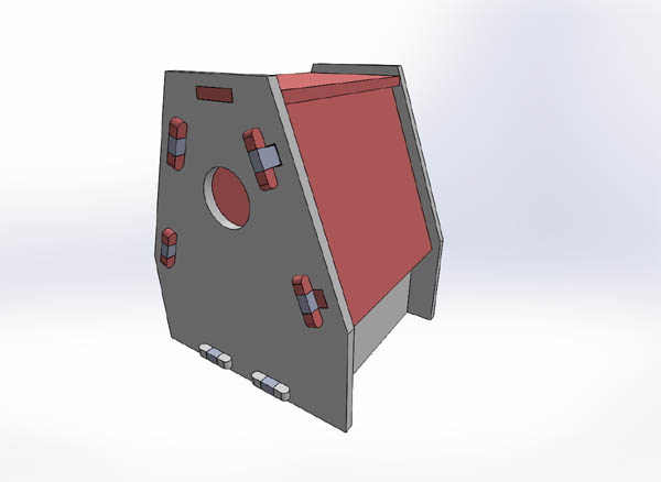
One of the above joining solution was selected to create the connections between the side walls of the birds house shown below.
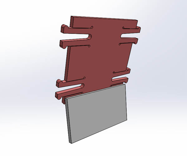
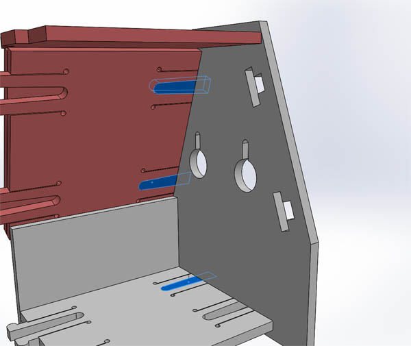
Below the side wall and inner roof is shown. The inner roof has snap fingers that will be blocked by an additional part.
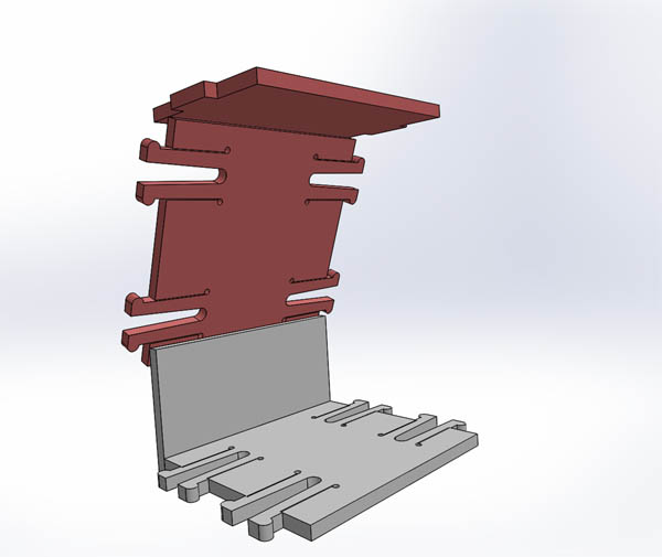
The bottom also has similar details. The top of the roof has a closed surface.
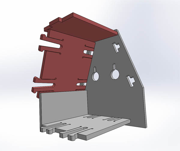
In blue the additional parts are shown. These will prevent the click fingers from coming lose.

The video below shows the Birds house all around.
From Github:
Frame. Click "view raw" to download.
Honing4 . Click "view raw" to download.
Joining1
joining_foil
joining_assy Click "view raw" to download.