

This week our assignment is about creating a network between two boards with each a micro controller. The network can be wired or wireless. In this case I will try to adapt this assignment to my main project. Therefore I had a discussion with my local instructor Emma. We spoke about the main architecture of the Beehive. Because it is too complicated to start working on it at once this was simplified into a basic sketch architecture. From there on a spiral way of working was proposed to start with running the stepper motor only. Continuing from there in different steps toward the final simplified architecture. Below all steps will be discussed in detail.
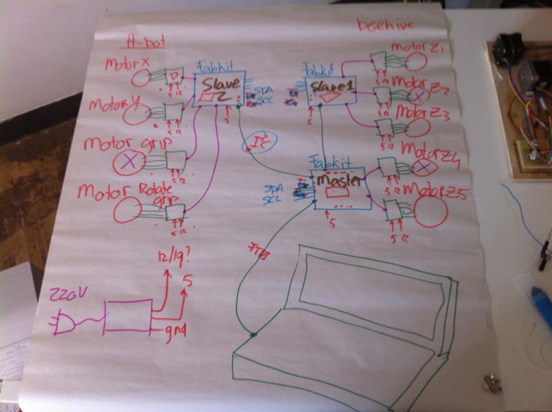
In the sketch below the main architecture of the beehive is drawn on paper. On the left you see the stepper motors for the H-bot including the gripper and rotation of the gripper. There are four stepper motors needed. Each motor has a motor driver and the driver will be connected to GND, 5V and 12V. These four motors will be connected to a Fabkit. In this case the Fabkit will be the slave of an other Fabkit. The movement from the motors should have end switches. For this moment it is not clear how many pins are necessary or available.
The slave Fabkit is connected to the Master Fabkit by using I2C. This means communication goes through four wires (SPA / SCL). On the right hand side the beehive with five drawers is drawn. Each drawer uses one stepper motor, so five motors are needed here. Two of the drawers are connected to the Master Fabkit, because there are enough pins. But not enough pins for all the motors and also here end switches are needed. To solve this a second slave board is connected to the Master Fabkit by I2C. Now the other three stepper motors are connected to the second slave Fabkit, including the end switches. To program the Fabkits the FTDI cable is used. After installing the FTBI cable is used to upload the G-code to operate the system.
Because above explained system is too complicated to start with, a simplified architecture was made. This is shown in the drawing below. What you see here is on the left one stepper motor connected to a driver board. The driver board is connected to the power supply 12 V and 5 V to operate. The 5 V is coming from the laptop USB-port. A Fabkit Slave is connected to the stepper motor driver, with GND, VCC, input one and input two. With the I2C communication the Master Fabkit is connected to the slave Kit using four wires. The master Fabkit is connected to the laptop by using an FTDI cable. This way it can receive the G-code instructions and send the information through to the slave board. One end switch is connected to the Master Fabkit. This will be the end stop for the motor motion.

Still above system is too complicated to start working on at once, so a spiral developing model is used here to start simple and make it more complete in different steps.
The spiral developing plan has the following steps.
step 1: Try to get the stepper motor running only, just with the motor driver and connected to a Fabkit.
step 1 alternative: If it takes to much time debugging the step above replace the motor with a led+resistor.
step 2: Implement Master - Slave (I2C) by connecting two fabkits. One as Master and one as slave. The stepper motor and motor driver are connected to the slave Fabkit.The Fabkit boards have no input switches. To keep it simple.
If it works: the program has to be 10 seconds clockwise turning and after that 10 seconds counter clockwise turning. If it does not work: debug the system.
Step 2 alternative: In case the stepper motor did not work and he led is used:
If it works: the program has to be turn the led on for 5 seconds and turn the led of for 5 seconds. If it does not work: debug the system.
step 3: When the second step works well, the next step is adding the end switch to the Master Fabkit.
If it works: the program must be: when the switch is open the motor is not turning. When the switch is closed the motor is turning. If it does not work: debug the system.

Two weeks ago the system below was made and due to problems it was not working yet. What we have here is: one Fabkit connected to two stepper motor drivers and they are connected to two stepper motors. The power board sources the power from an adaptor and supplier 5V for the logic and 12V for the motors.
Two weeks ago I had big problems because I connected 12 to GND on all boards. The damage was a fried micro controller and a fried regulator. After replacing these it was possible to program the MC by using Arduino IDE.
Unfortunately the Arduino Sketch "one turn" did not do anything. Together with my local instructor we tried to debug the system. First with replacing the Fabkit with an Arduino Uno. Here we had no result. all traces and connections were measured through. The final conclusion for now is that all h-bridges are fried as well, because they also had 12V connected to GND. By replacing them I hope to solve this issue soon.
Some other things we discovered, and could be an issue: In our Fablab we had only the A4950.....
In other projects they use A4952-3....
Comment from two weeks later: It became clear that the A4950-driver is meant for using in DC-motors and not for stepper motors. In a discussion with our second instructor Luis is became clear that A4988 (1.2 amp) can be used for stepper motors of if there is more current the DRV8824/25 (2amp) (Geckodrive).
The big stepper motor is not suitable for 12 V, it needs 24 V, so this can not work. The other motor should work on 12V.
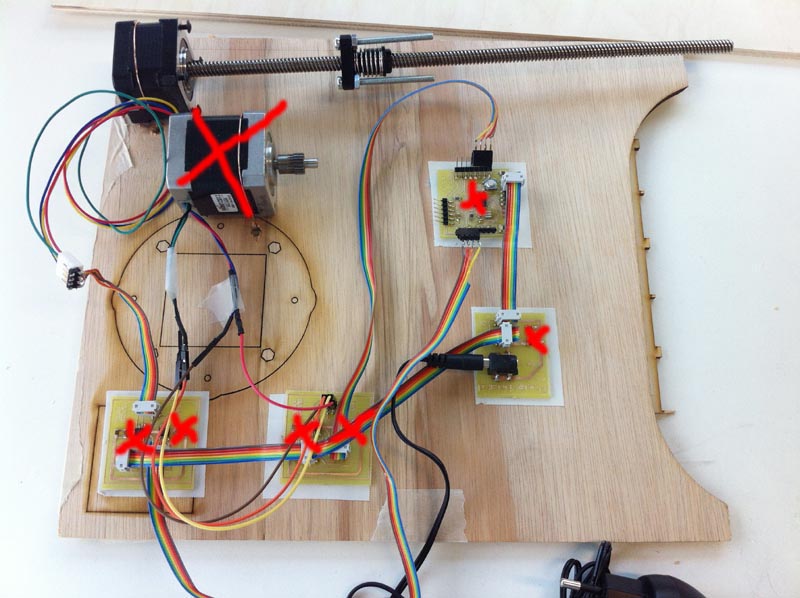
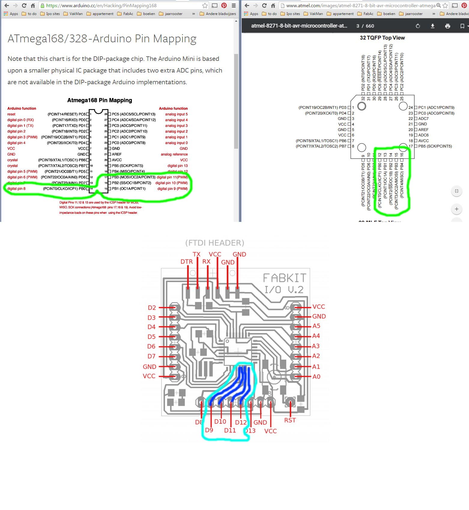
In the picture below it is figured out how to connect the motor to the pins. Still it is not really clear if phase 1 is pin 8 and 9 and phase 2 is pin 10 and 11. I assume it is...
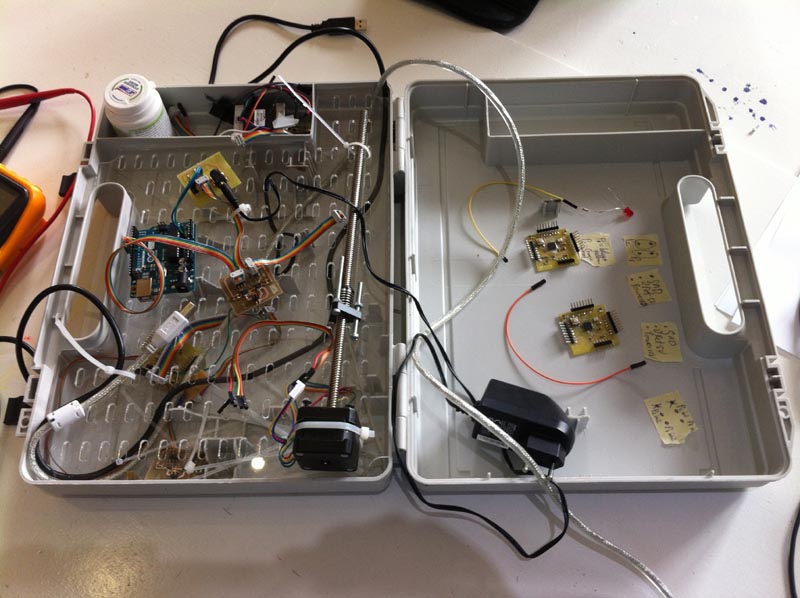
The board and the hardware glued onto it were too fragile to transport each week, so I decided to use a protective case. Inside this case a PMMA plate was made with the lasercutter. Onto this plate the different components can be attached using Ty-wraps.
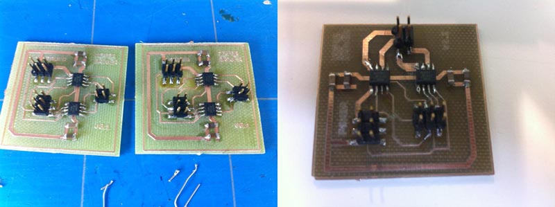
Two new motor driver boards were made because the traces from the chip to the output connector were too thin. The current for the stepper motor should go through these traces. Below picture shows the milling of the boards inclusing two new Fabkits. The material looks darker then normal, because at the bottom there is also a layer of copper.

The components from the old power boards were de-soldered and reused, except from the H-bridges. These were replaced by new ones.
Now it was possible to connect my first fabkit to the power board, the motor driver, the stepper motor and the power supply.
To test if the stepper motor was working a sketch was uploaded.
The result was negative...
To eliminate the possibility that my first fabkit was not working well, this fabkit was replaced by an Arduino Uno.
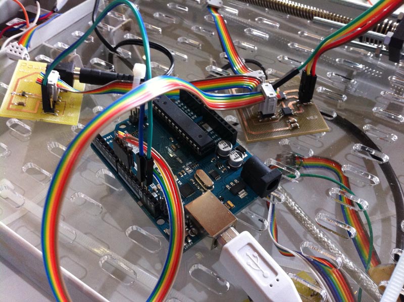
The same arduino sketch was uploaded.
The result was negative...
Measurements:
Power board: supplies 5V and 12V Arduino is supplied with 5V Motor driver is supplied with 5V and 12 V Connections GND, Power and 5V is good ... needs debugging....
Initially it did not work and after measuring and debugging a very basic mistake became clear. The VBB (Powerconnection to the motor driver) was not connected on the board. This was solved with soldering a jump wire.

A standard sketch from Arduino was used to run one revolution clockwise and one revolution counter clockwise.
Now the motor is turning!!! But it makes strange sounds.....
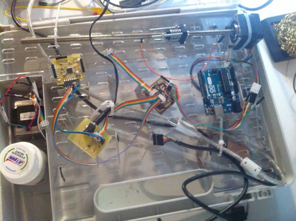
Sound improved for unknown reasons....
The motor drivers are not good for using on stepper motors, this is probably the reason for the strange sound on the motor.
So according to the plan I had to replace toe stepper motor with an LED+resistor. In the beginning this also did not work. Later I found out that the LED was not working. So I replaced the LED.
Now it is possible to blink the led using the "blink" sketch.
So in this step two Fabkits will be connected as Master and Slave by using I2C. The slave is connected to the motor driver from the stepper motor of a LED+resistor. There are no end-switches.
To make this possible I have to make new Fabkits. Because making a Fabkit is a tricky job, where many things can go wrong, I decide to make two boards at the same time. This in case one is not working.
The BOM for a kit is:
Part Value Device Package Description
C1 .1uf C-EUC1206 C1206 CAPACITOR, European symbol
C2 1uf UNPOLARIZEDCAPACITOR1206 1206 unpolarizedcapacitor
C3 .1uf UNPOLARIZEDCAPACITOR1206 1206 unpolarizedcapacitor
C4 10uf UNPOLARIZEDCAPACITOR1206 1206 unpolarizedcapacitor
IC1 ATMEGA328P48/88/168-AU ATMEGA48/88/168-AU TQFP32-08
JP1 FTDI PINHD-1X6/90 1X06/90 PIN HEADER
LED LED1206 1206
PAD2 WIREPAD2,54/0,9 WIREPAD2,54/0,9 2,54/0,9 Wire PAD connect wire on PCB
R1 10k RESISTOR1206 1206
R2 499 RESISTOR1206 1206
S1 6MMSWITCH6MMSWITCH 6MM_SWITCH OMRON SWITCH
SV1
SV2 MA08-1 MA08-1 PIN HEADER
SV4 MA08-1 MA08-1 PIN HEADER
U$2 RESONATOREFOB RESONATOREFOB 16megaHz EFOBM
The boards were milled on our LPKF-milling machine. Soldering the micro controller was really not easy, because the traces are (too) thin. And also because I did it with the wrong soldering iron. The result was too bad, broken / burned traces and solder connections between pins. Because of there problems I had to mill two fabkit boards again. With the big soldering iron and an other soldering technique it was possible to silder the two mico controllers to the boards.
After soldering it was time to beard the boatloaders, by using the spacial made wire connection and the USB-tiny.
Fabkit 1P:
CMD-check 1P:

Upload simple sketch 1P:

Fabkit 2P:
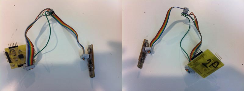
Burn the boatloader
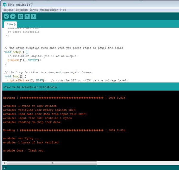
CMD-check 2P:

Upload simple sketch 2P:

Test program the MC:
Fabkit 3P:
Burn the boatloader
Image is missing.
CMD-check:

Upload simple sketch 2P:

Test program the MC:
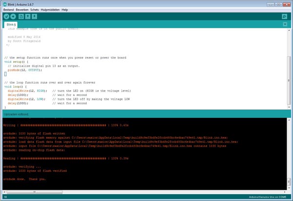
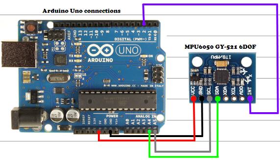
The result for now is two new fabkits and one of them is not working yet. Now it is tie to connect the boards to each other by using the I2C connections. These are two wires on ... and ... Apart from that it is necessary to connect ground and VCC as well. The Fabkit 1P (master) is connected with the FTDI cable to the laptop. This makes the serial reading possible. The Fabkit 3P has a LED+resistor connected to it ( in stead of a motor driver + stepper motor).

Programming
Program: - turn motor 10 sec cw - turn motor 10 sec ccw
Program in case of a led + resistor: - switch open: led is on - switch closed: led in off
If it works: continue with got to step 3. If it does not work: debug it
Program: - switch is open : motor on - switch is closed: motor off
To test if the i2c network works, two sketches are uploaded to the master and slave Fabkit. From the master it is possible to use the serial read function through the FTDI cable to the laptop. The sketch on the slave Fabkit is sending a 6 bit message over and over after each other. In this case the message is "Paul_!". The video below shows the set-up from the networks and its performance, and it works.
Directly from this site:
master_i2c
switchcheckfabkitserial
slave_i2c