

This week our assignment is about moulding and or casting a "plastic" product. For me this is not a very difficult week assignment because I have much experience in designing plastic products. When you design the part you have to know hoe the mould should work. Before the briefing of the assignment I thought the mould could also be a 3d printed mould. I wanted to cast the bottle I printed earlier in week 5 (link). It became clear that the assignment was different and there fore I changed my product. First I designed a new casing with an additional credit card feature for my iphone. However this has nothing to do with my main project, so later I decided to design a "gripper" for my beehive. The gripper is the replacement from the hand of a bee-keeper. On this web-page I will first explain how the gripper is made and after that I will also talk about the iphone casing and bottle from week 5.
The inspiration for the gripper comes from the end effectors from the Festo - MultiChoiceGripper. This gripper comes in two versions. One with multiple parts and rotating hinge points and one made out of one part with flexures as hinges.


The basic idea behind the gripper is that a linear motion is transformed into a rotating motion of the gripper arms. In this case the shape of the arm is also changing so the arms are clamping around the object.
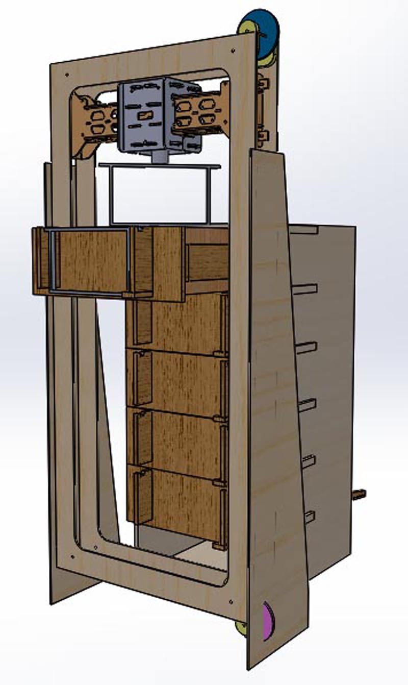
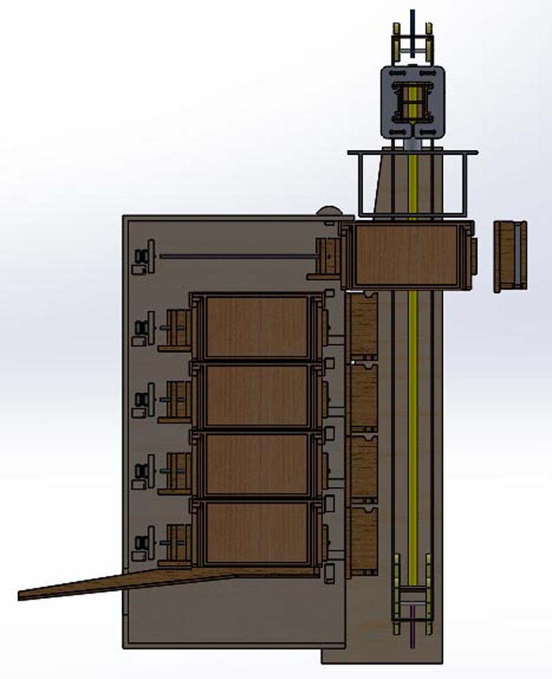
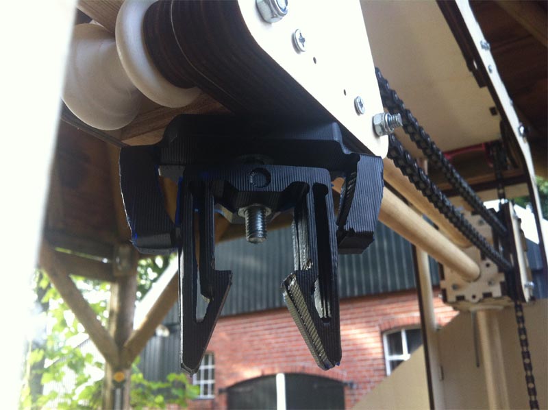
The beehive has a limitation in height so the length of the gripper can not be as long as the Festo solution. The pictures below show the location of the gripper. The function of the gripper are: (1) clamping and holding a frame from the beehive. (2) transporting the frame to an other location (3) rotation the frame 90 degrees and (4) releasing the frame at a certain position


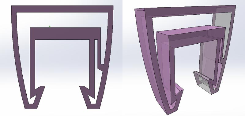
The design of the gripper was developed in different steps by doing simulations on the movement. At the top of the part the linear displacement is for instance 3 mm. With this translation the two arms have to move about 6 mm to grip the steps in the frame.
The video below shows the different simulations on the parts. The aim was to find 6 mm rotational motion of the arms of the gripper at a linear motion from 3 mm. By doing the simulations it was possible to make the part stiff where it should be stiff an let the part flex where it should flex.
The pictures below show the different steps of the design.
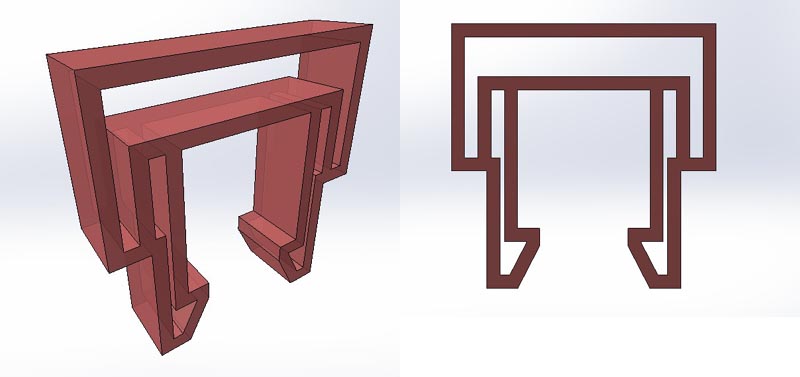

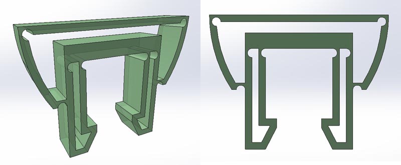
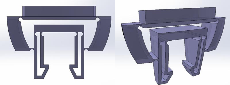
The final part in CAD looks like in the picture below.
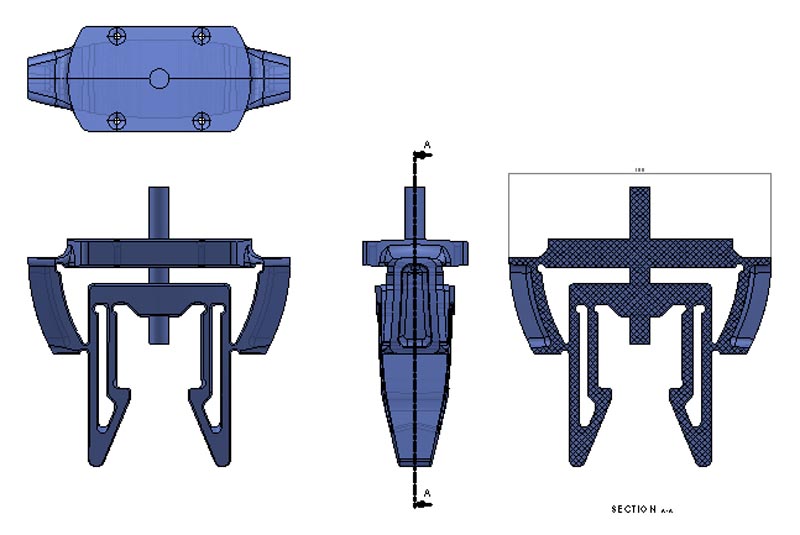
The assignment is very specific and this locks out other solutions for moulding. The steps to take are: 1. Create the CAD file for the wax model. This should be a positive shape of the part 2. Make a positive wax model of the positive shape of the part. In most cases there are at least two halves of the part necessary. These parts will be milled out of a wax material on the Shopbot. 3. Pour a silicon in the wax model so the negative mould will appear. 4. Close the silicon mould halfs together and cast a specific PU- two component thermoset material in the mould 5. Produce more of the same parts with the moulds, in different materials if possible
In the following explanation the steps above are described more briefly and with all the details.
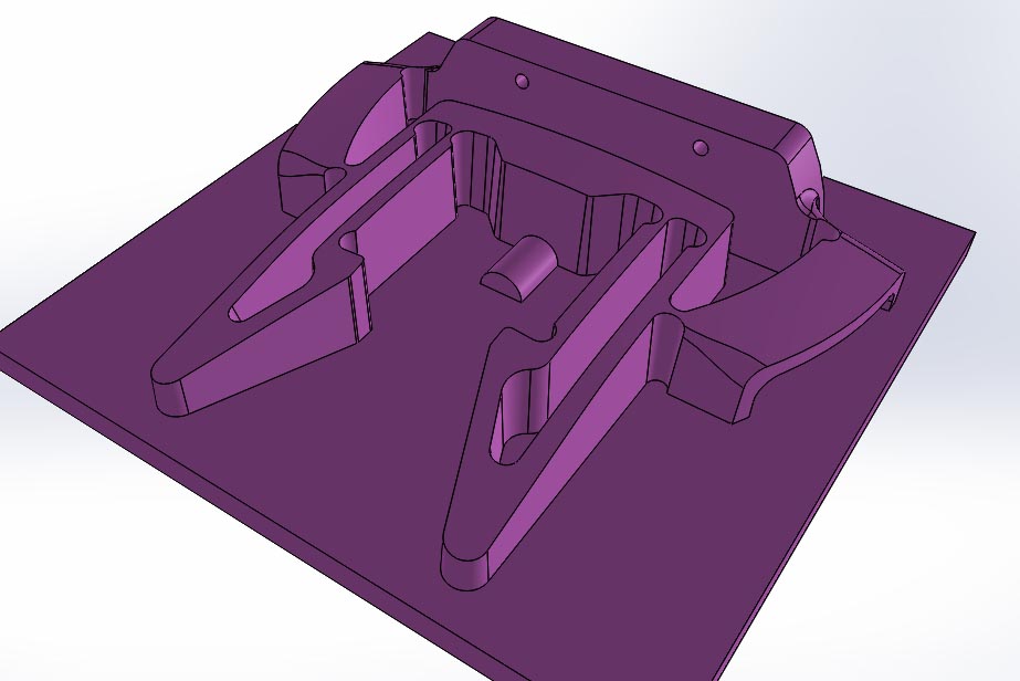
Here the main modelling steps in Solidworks will be explained. The picture below shows half of the part with a base plate underneath. Different features of the mould will be added chronologically.
In Solidworks it is possible to do a draft analyses. In the picture below the red areas are the problem areas. The little hole will be made after molding the part. But the shape on the side will be made in the mould. To do this the mould needs slides. These are separate parts that move in a perpendicular direction.

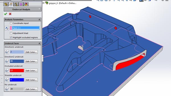
There is also another feature in Solidworks, to show undercuts in the main direction of the mould. In the picture below the undercut detection is shown. Also the red areas are the problem areas. Two slides can solve the big red areas and the little holes will be added later after moulding the part.
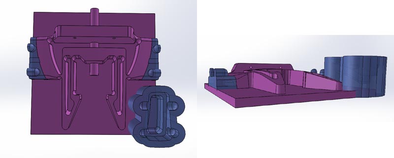
In the picture below the slide is drawn on the position where it is needed in the final mould. The x-section on the right shows that the slide is going underneath the part. This is only half of the slide.

The final mould needs two similar halfs and two slides. Because it is possible to combine the mould parts into one wax mould I decide to go for one wax model. To do this I manipulated the slide to another position. The part is a body in the same part as the big mould half. With a linear pattern the slide was copied to the right (see picture below).

With the mirror function the slide was made complete as shown in the picture below.

Now it is almost time to move the slide to its right position in the wax mould, but the shape has to be negative. To do this I subtract the slide shape from an offset shape.

Now the negative shape of the slide can be manipulated to the right location with the feature move/copy.
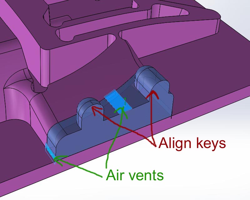
On the position of the slides air vents are added to avoid air entrapment. To define the end position of the slides alignment keys are added to the slides.
Now the four bodies within one parts are combines together in one body.

For the silicon pouring a wall around the product is needed. In the picture below the wall is modelled in the Solidworks file.
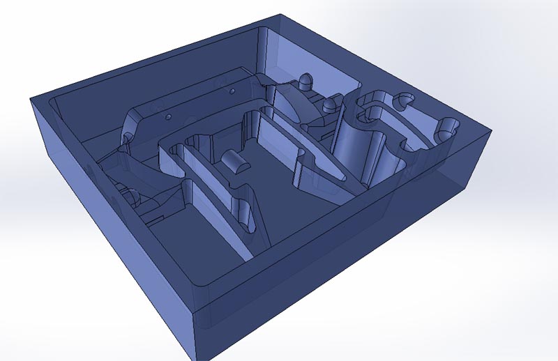
To make sure the two main parts of the mould align with each other, four alignment keys were added to the mould. They need to be placed symmetrically. The keys are holes in the silicon mould. These holes can be aligned with additional pins.

For injection the liquid plastic material there are two optional holes defined. By breaking of two pillars on the left in the picture below, the injection tubes can be created in the red drawn area.
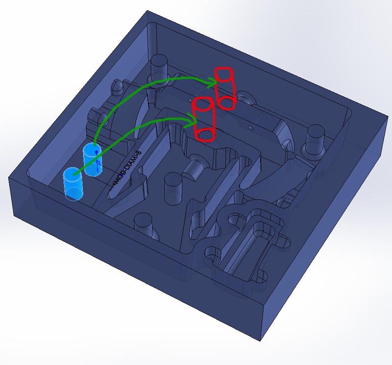
In the picture below half of the mould is displayed with the air-vents indicated in light blue. The function of the air-vents is releasing the air that can be entrapped in the mould cavity.

Now the CAD-model is ready. The outer dimensions are bigger than the standard dimensions from the machinable wax blocks. For this reason a concrete plywood mould was made. The standard wax blocks were melted and casted into the wooden boxes. Here a mistake was made because the wax material shrinks when it cools down. The shrinkage was about 5 mm on a length of 120 mm. It would be better to make the mould about 5% bigger to compensate the shrinkage.

Below some pictures from the silicon mould assembly with product rendered in green.

In a special ceramic oven with a nice thermostat the temperature was adjusted on 240 degrees Celsius. In my opinion quite high but necessary. The wax was molten in a sheet metal box and after that it was poured into the concrete plywood moulds. To avoid crack while cooling down they were placed inside a kitchen oven that was just used as an insulating box. The oven was not switched on. Both boxes came out quite nice. The only problem was that the block was about 5% smaller. For this reason the side walls of the milled wax blocks are too thin.
The video below shows the melting process.
Now the CAD file and the Wax block is ready, so milling can begin on the Shopbot
The first step in the milling process is mounting the wax block to the machine bed. In this case double sided tape is used and strong tape on all the edges. This to avoid the part from coming lose when milling.
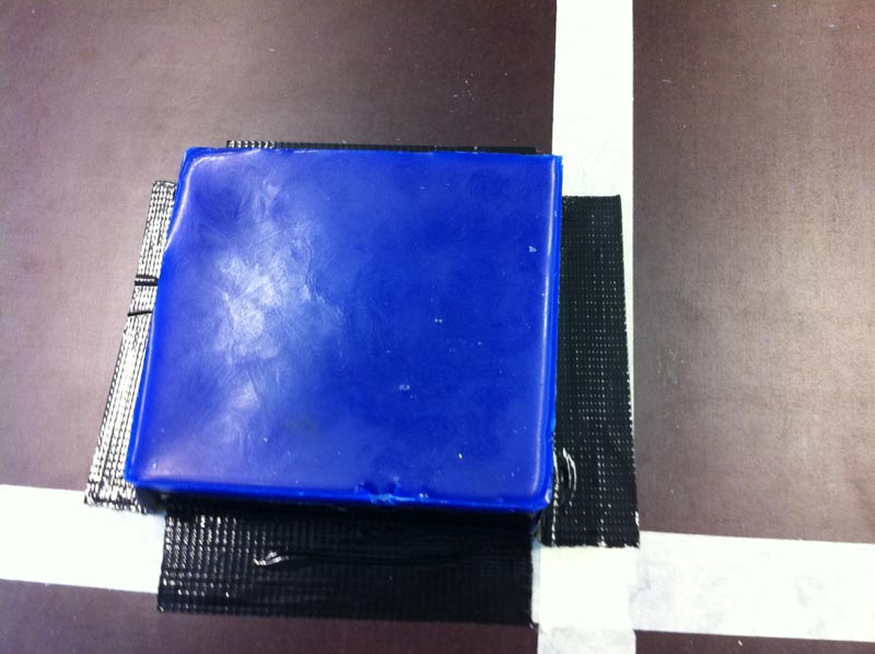
Because the top of the wax block is never flat after casting, it is nesecerry to level the top of the block by milling. This can be done with the 2d shopbot softwre, using a dxf and a pocket function.
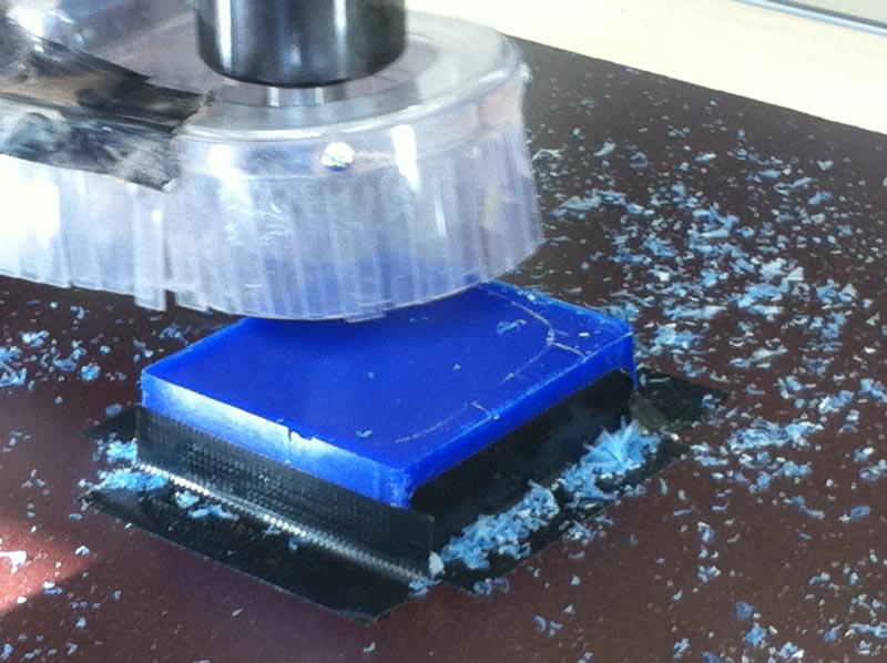
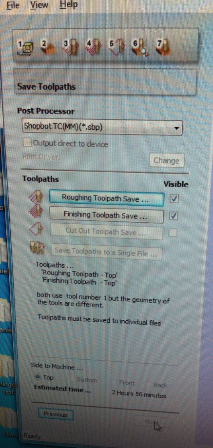
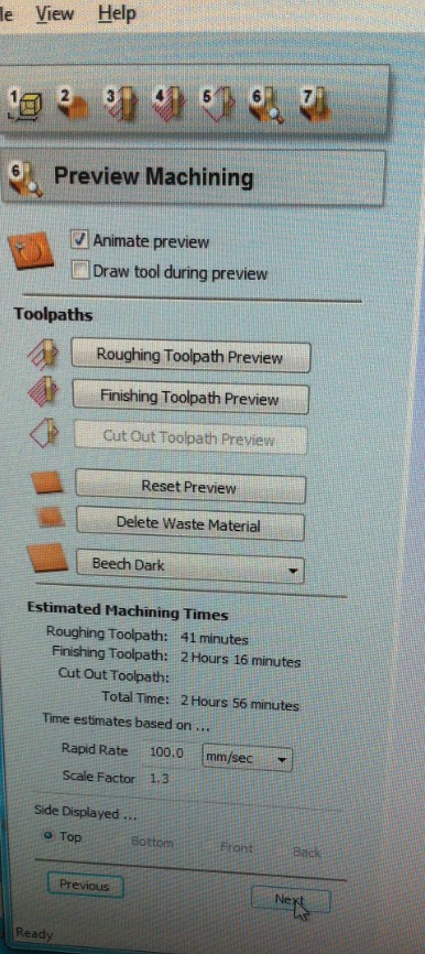
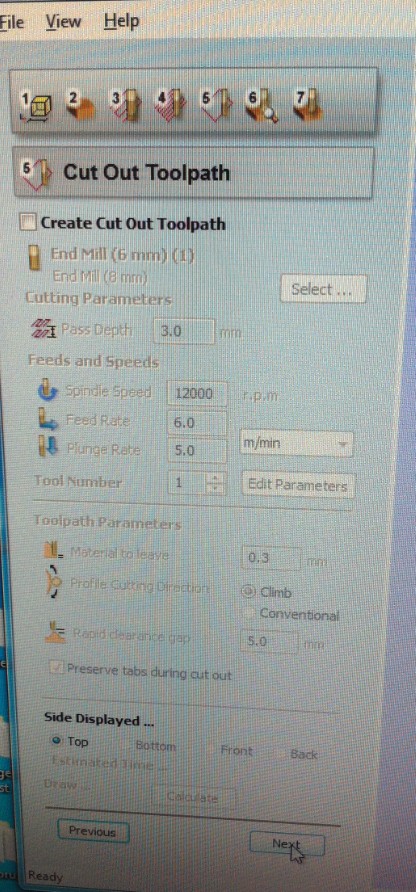
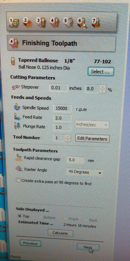
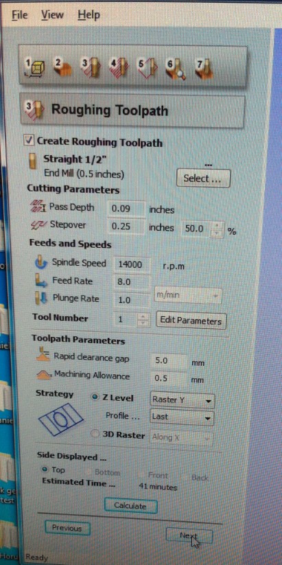
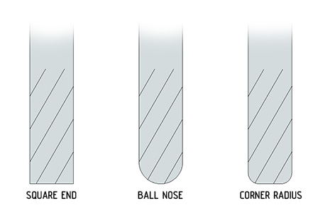
The 3d milling goes in two steps. First the rough milling and then the finish milling. The rough milling takes away all material until an offset of the product. This is for instance 0.5 mm. This last layer of material is milled away in the finishing step. So there is a big difference in the two steps. In this case I decide to make one mould with an round milling bit and one mould with an end mill. Both diameters are 3 mm and the shaft is 4 mm. This is actually a problem with deep milling. This will be explained later.
 |
 |
 |
 |
 |
 |
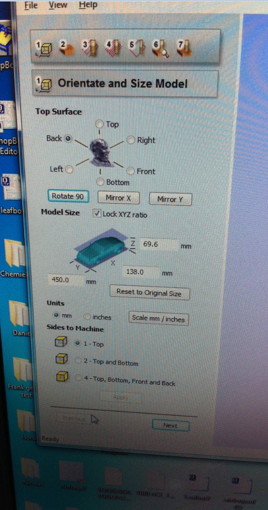 |
In the video below the simulation of the milling is shown. This is an important step in the process. Mistakes in the milling process can be filtered out here.
The choice for a round mill was in this case not a good idea, because the separation line or parting line of the mould half should be sharp.The parting line is the deepest surface of the milling process and with a round mill this always gives a radius.
The result of the milling is shown below.

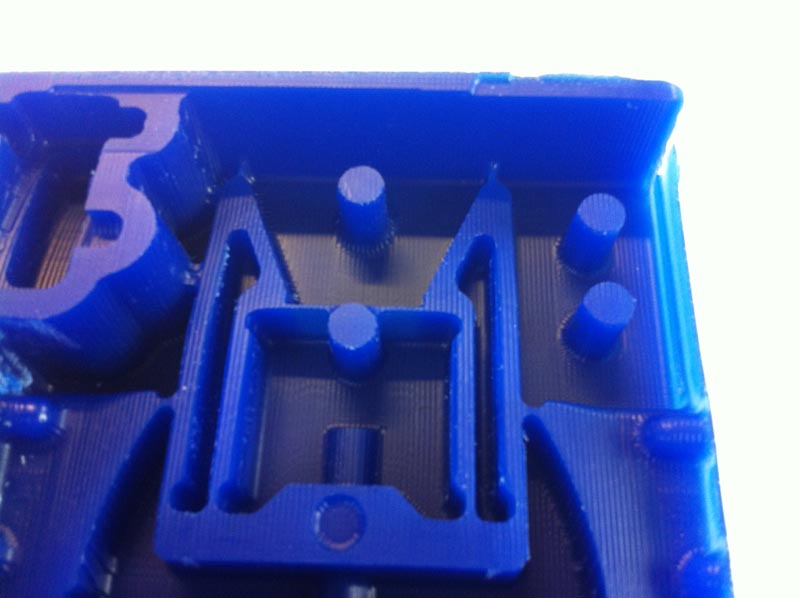


Issues in the milling process: 1. Mill was not sticking out enough so the mill clamp went into the wax block. This could be solved in the process by adjusting the mill height and re-zeroing the mill. 2. A draft of 3 degrees was added to make milling possible for a 3 mm mill with a shaft of 4 mm. This goes well at two side walls but on the other side walls the mill goes into the material. There is no solution other than using a 3 mm shaft mill. 3. Milling should be done with a squared end mill I think. 4. Resolution of the finish milling can be much finer. This was done in the second mould. 5. Side wall of the block wax is too thin. This can be solved. 6. The mill had an error and went right through the part at one time 7. By adding the draft just before milling, the distance between one arm and the side wall was smaller than the diameter of the mill. This means that the mill is not going to mill the material there. I did not see this problem in the simulation. After milling I had to rework this manually. This was not easy to rework. Reworking the wax makes the surface very rough and ugly.
The next step is mixing the two components of the silicon (brand??). It is important to stir slowly and avoid air bubbles. The mould was taped around to create a side wall and placed in an angle to prevent air entrapments.
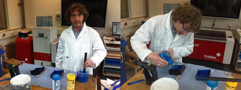
Now both moulds are filled with silicon as shown below.
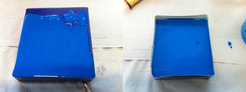
The result of the silicon casting process is shown below:
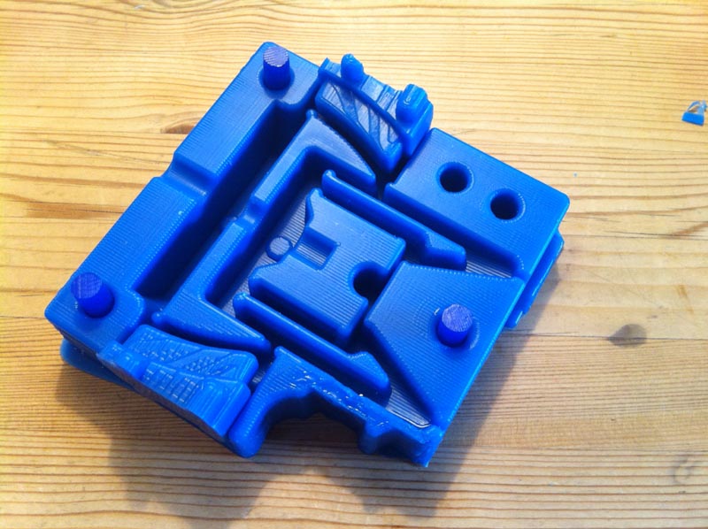

In the picture below it became clear that all edges of the parting line are rounded. This should not be like that. This was caused by selecting the wrong mill (rounded mill).

The second mould has sharp edges like it should be, as shown in the picture below.

To translate the linear movement to the two side arms the horizontal beams should be as stiff as possible. The moulding material is a PU rubber like material and is not stiff at all. For this reason I decided to use steel inserts.
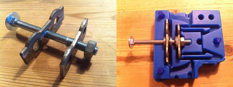
To prevent the PU-material to stick to the metal bolt, hair wax was used as a release agent.
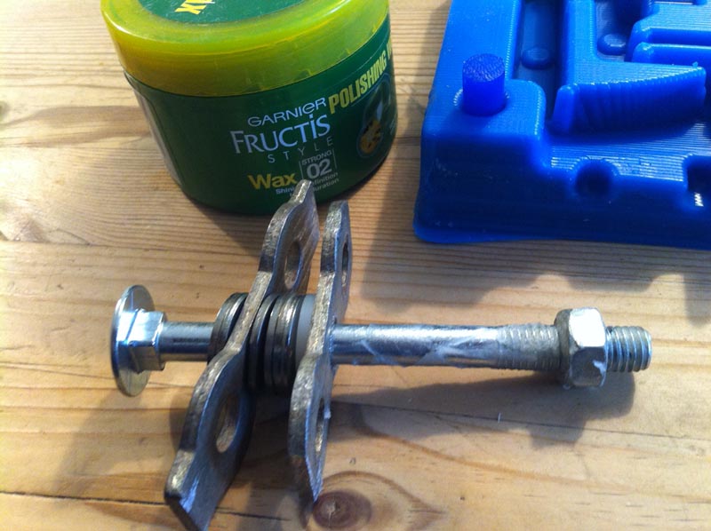
Silicon kit was used to seal the mould parts together.
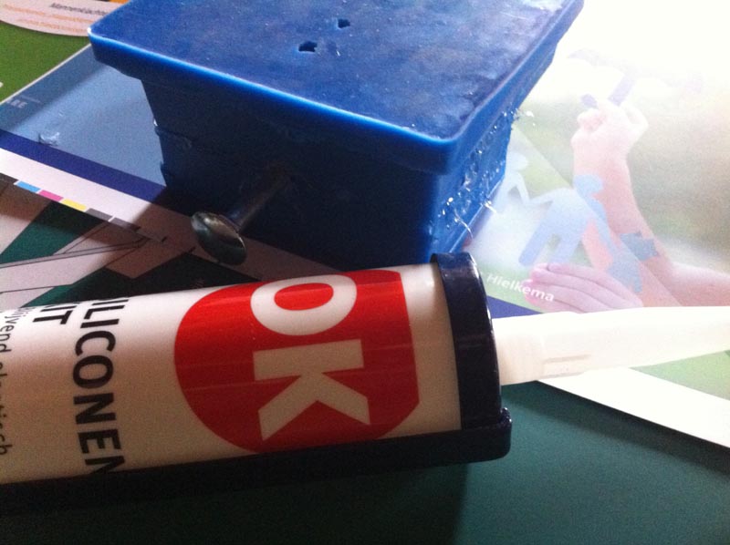
Now the mould parts and the inserts are assembled it is time to mix the PU-component A with the colour and than add PU-component B (brand???). Mix it all very well together and avoid air bubbles. With an injection tube the material was pushed into the mould.

By pushing slowly the material into the mould I tried to avoid air entrapment. The pressure on the slides however was to high and the shape of the slides was not interlocking so the slide on one side came a little bit loose.

With the help of some materials by hand it was possible to hold the slide in place as shown in the picture below.

The temperature at casting was too low, maybe about 7 degrees, so after filling the mould I placed the mould next to the wood stove.

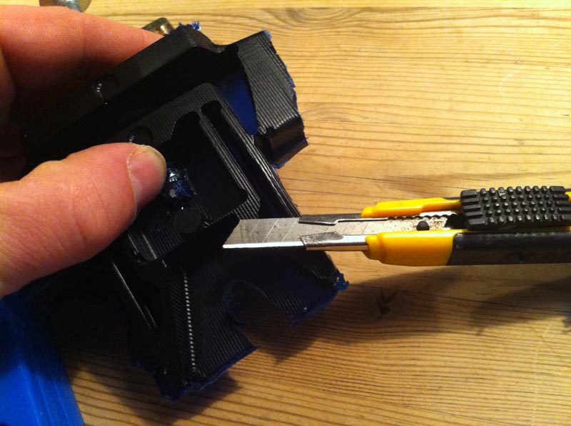
About six hours after filling the mould I opened the mould to see what was going on. One side of the part had many air bubles and the other side was actually very nice and smooth. There was a lot of flesh all around the part. With a sharp knife this was cut away. The hair wax as release agent between the bolt and the PU-material worked well. I could take it out by hand. With an 8 mm drill I drilled out the hole because the bolt shaft diameter was a little too small.
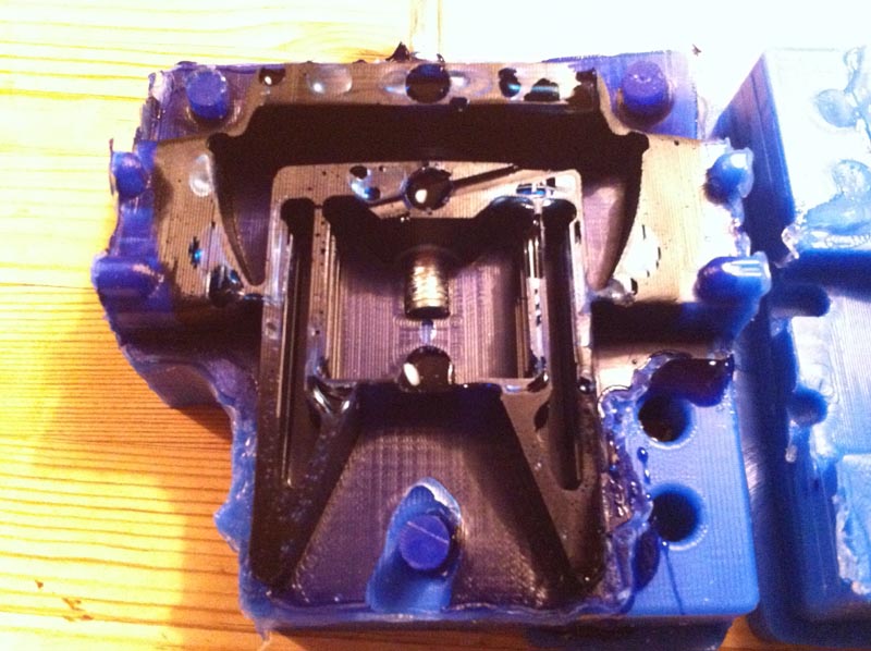
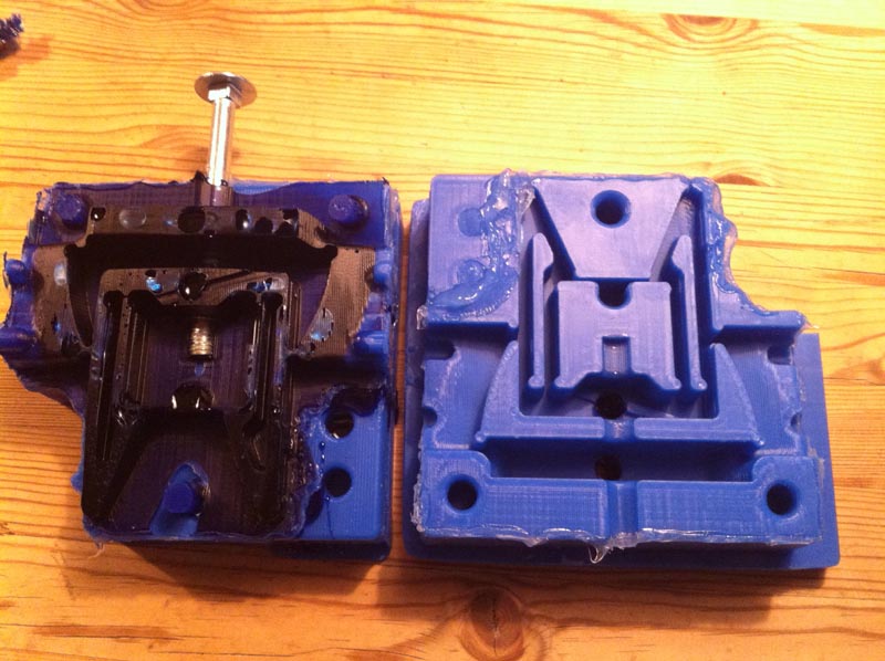

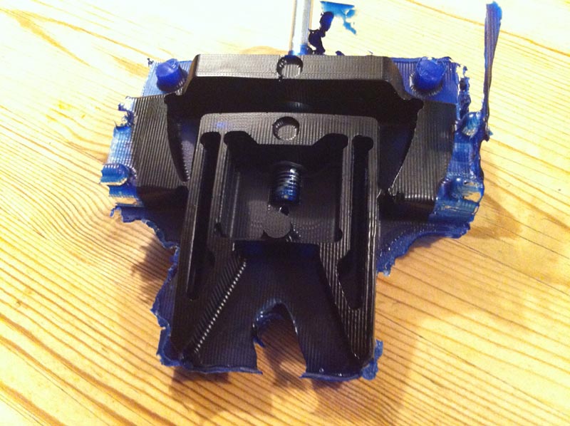
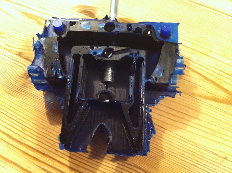

The video below shows that the part works as it was designed to work. With a translation along the bolt from about 3 mm, both arme move about 6 mm inwards to grip a frame from the beehive.
This week I ran out of time, but I will make some more castings later I think.
Here are the files from the gripper.
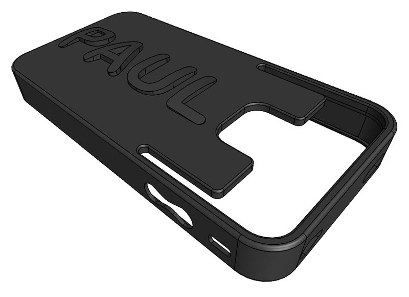
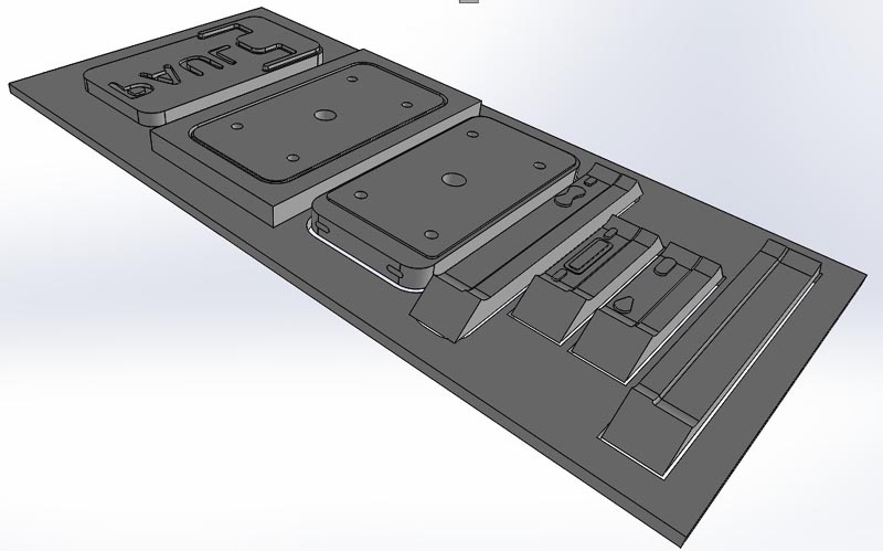
In the beginning of this week I thought about making a new casing form my iphone. Herefor I made a design with additional features like a credit card holder and an embossed name. The mould was drawn in Solidworks.



The beeswax bottle will be moulded out of beeswax into a 3d printed mould. The pictures below show how the mould will work.
I don't give comment at the pictures below.


From Github: Beeswax honeypot plus 3d printed mold for casting.. Click "view raw" to download.