Electronics production
Assignment: Make the Fab (tiny) ISP in-circuit programmer
Learning outcomes:
- Describe the process of production and programming
- Demonstrate correct workflows and identify areas for improvement if required
This week was all about electronics production, specifically printed circuit board (pcb) fabrication. The goal was to make a Fab ISP. This was done in three steps:
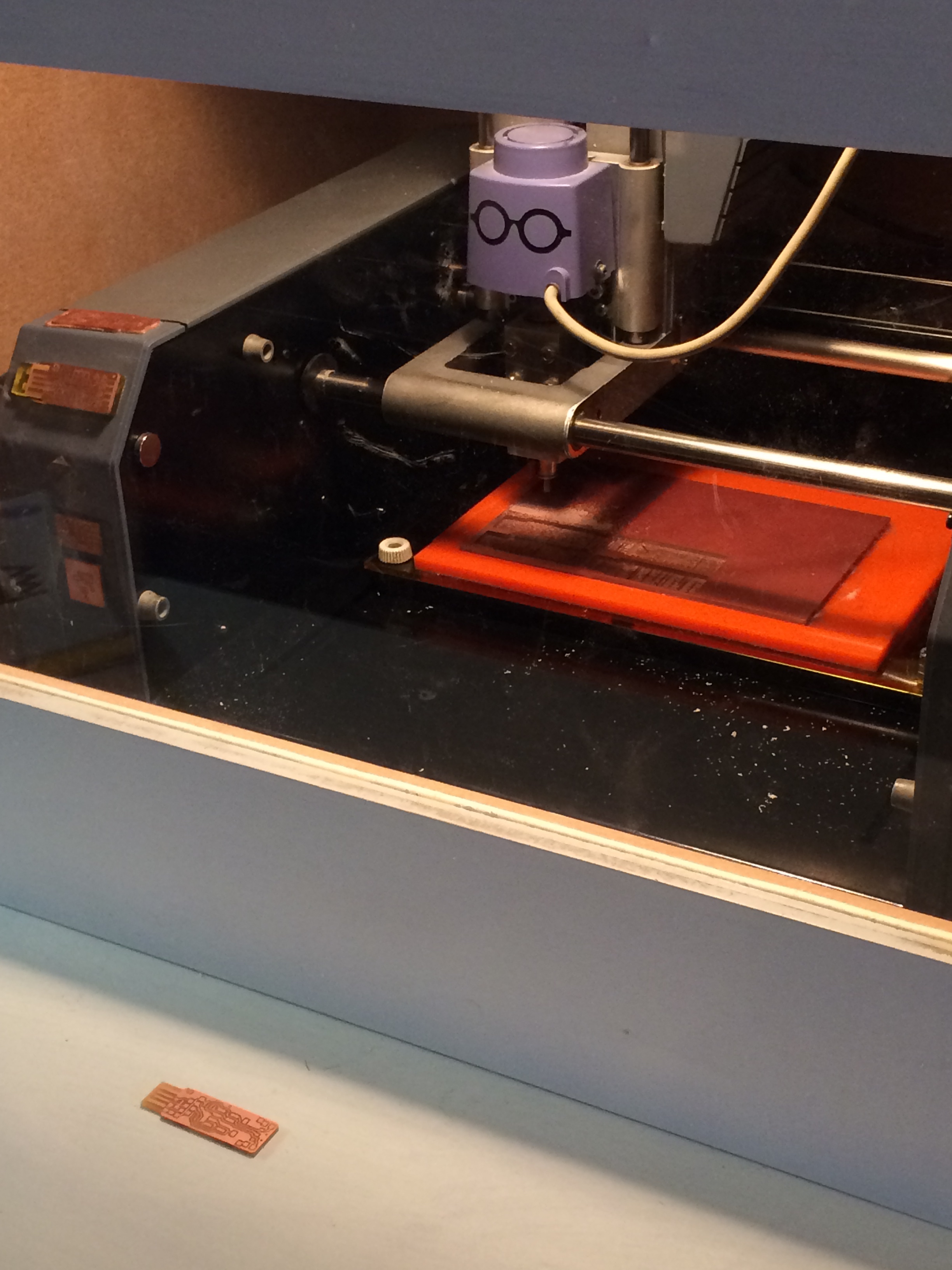
1. Using a Roland Modela to mill the PCB
2. Populating the board
3. Testing the board for programming
What is a Fab ISP?
The Fab ISP is an in-system programmer for microcontrollers (mini-computer devices), designed for production within a FabLab. It allows you to program the microcontrollers on other boards you make.
1. Milling the PCB
To create the PCB, we used a Roland Modela. First, I watched the others going through the process, which helped me a lot in learning what mistakes not to make; make sure to properly set the z-axis so that the end mill really goes through the copper, do not set the end mill too loose as not to break it, press and hold down the up and down button to reset completely... Eventually, mine came out 99% perfect (according to Cicilia). One trace looked a bit dodgy, so I asked other experts and tested with the multimeter. Conclusion: For the extra 1% the option was to use my nails or a stanley knife to improve the board, or to mill it all over again.
The next day, I produced another board.
Important steps:
- On the bed of the milling machine, place the acrylic plate on the sacrificial layer (make sure this is evenly balanced, using double sided tape)
- Turn on the milling machine
- Put the 1/64 end mill in the machine for first milling the traces
- Open up Fab modules using the command 'fab' in the terminal
- Enter the needed information (i.e. Source file: .png, 'process': Roland Modela)
- Then, load the .png file (of your choice) with the traces for the FabTiny (like everyone at the Waag, I used Zaerc's model which has extra LEDs)
- Set the other fields (i.e. Offsets: 4, Overlap 0.5, intensity: 0.5, speed 0.4mm/sec) and the absolute coordinates to move from (write these down, as you will need these later on)
- Do not forget to 'Make path' (you need to do this every time you make changes to the settings)
- Set the z-axis: Lower the end mill (it takes some noise and seconds to lower down; do not worry) so it touches the top of the material. Make sure to set and tighten the screw again so to secure the end mill
- Click "make rml" to create the file and click the "Send it!" button to start the milling machine
- You can use 'View' to pause the machine (and have a look) and remove the remaining dust with a small hoover.
- Do not forget to change to the 1/32 end mill settings for milling the outer layer
- You can use a 'spatula' to take off the board.
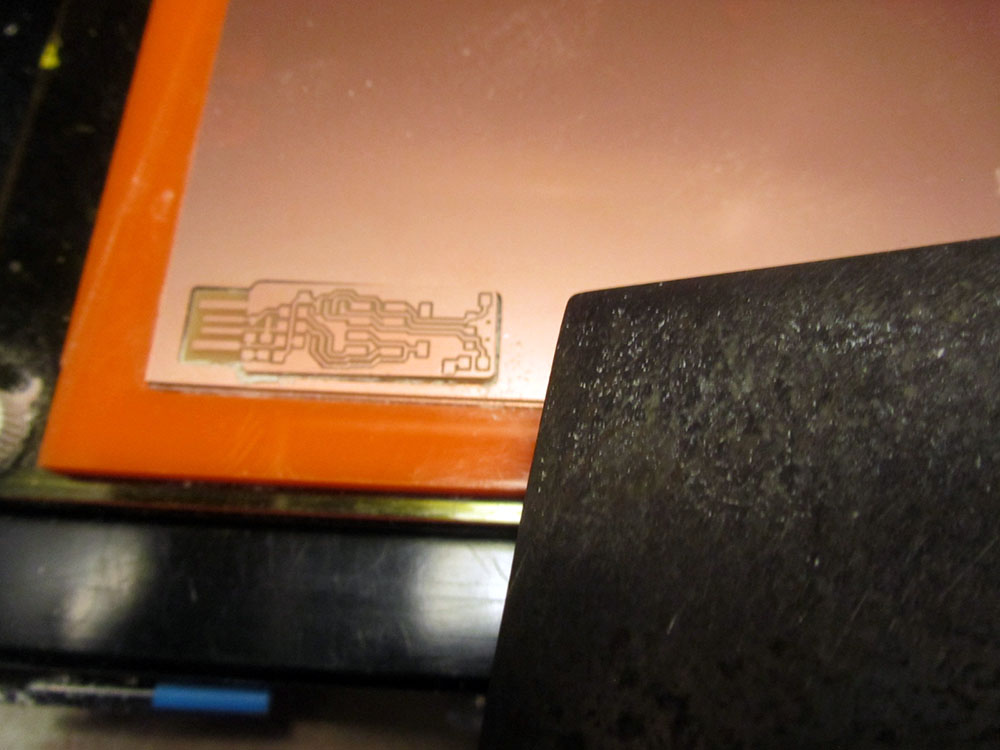 It turned out I should have put the Offset setting to 4 (instead of 1) as now the USB part was not fully traced. Using the stanley knife I was able to correct this mistake, so to continue to the next step: populating the board.
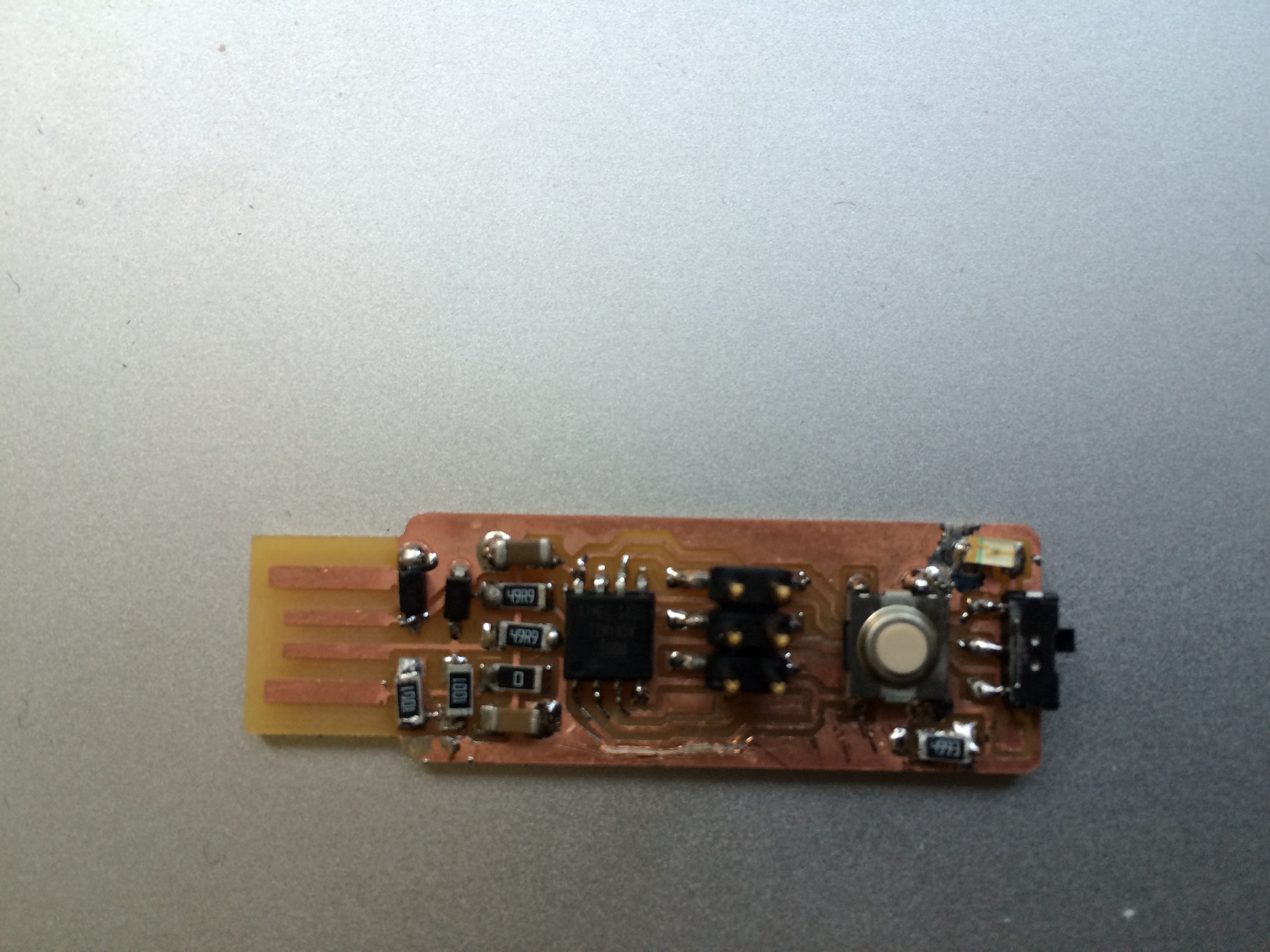
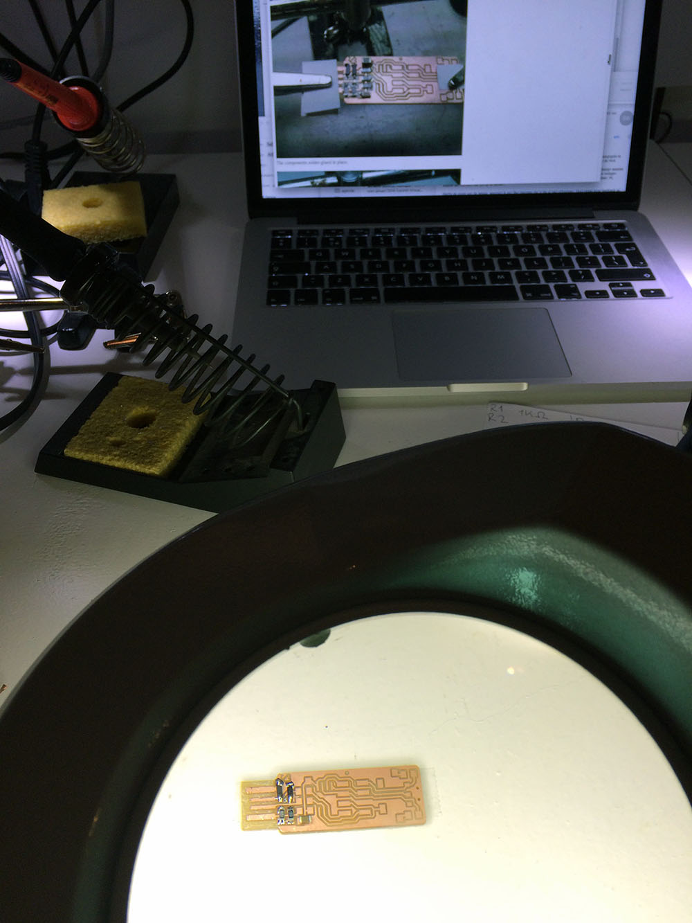
2. Populating the board
At first I was a bit hesitant to solder the components on my brand new board, so I decided to just practice with my first board, which was not 100% perfect anyway. I washed the board and used adhesives to stick the board to the table (the third arm was taken). Using a sheet with all the needed components written, together with the online tutorial really helped to get the soldering process in order.
 Now, soldering on such a tiny scale is not an easy process, even with a magnifying glass. One little mistake can make a big difference...
 Testing the board
In my wave of enthusiasm of having finished populating the board, I accidently removed a component. After resoldering this part, it was finally time to test it. The multimeter made the right beeping sounds. However, when Emma plugged it in her machine it turned out it was not getting any power. Looking at the board again, the ATTiny 45 component looked a bit too loosely soldered. Fixating this little issue did the trick, the board was working! Well, it turned out it was not working consistently... Looking at the board, the soldering was a bit flawed, thus the decision was to improve this first, before programming it. In my time consuming attempt to better the soldering I made it worse, resulting in short-circuiting the board.
I still had the other '99% perfect' board I milled, so the decision was to improve my soldering skills by redoing a new board from scratch. This turned out to be a true battle in terms of fading concentration and perseverance. Eventually, I completed this board. After carefully looking and solder tweaking again, it worked! The sight of the blinking LED light on the board was beautiful.
 Programming the board
By the time I had finished the second board it was time to go home. However, together with Emma we also embarked on the last step: to program the ISP and put firmware onto it. This involved following this tutorial step-by-step (skipping the Arduino Uno part). We succesfully completed all the steps (such as initializing communication with my ISP!) 'till 'Blowing the reset-disable fuse'. Because you can no longer program the FabTiny*ISP afterwards, make sure everything is working properly before taking this final step...!