Week 5 Week 9 Week 13 Week 17 |
Week 6 Week 10 Week 14 Week 18 |
Week 7 Week 11 Week 15 Week 19 |
Week 8 Week 12 Week 16 |
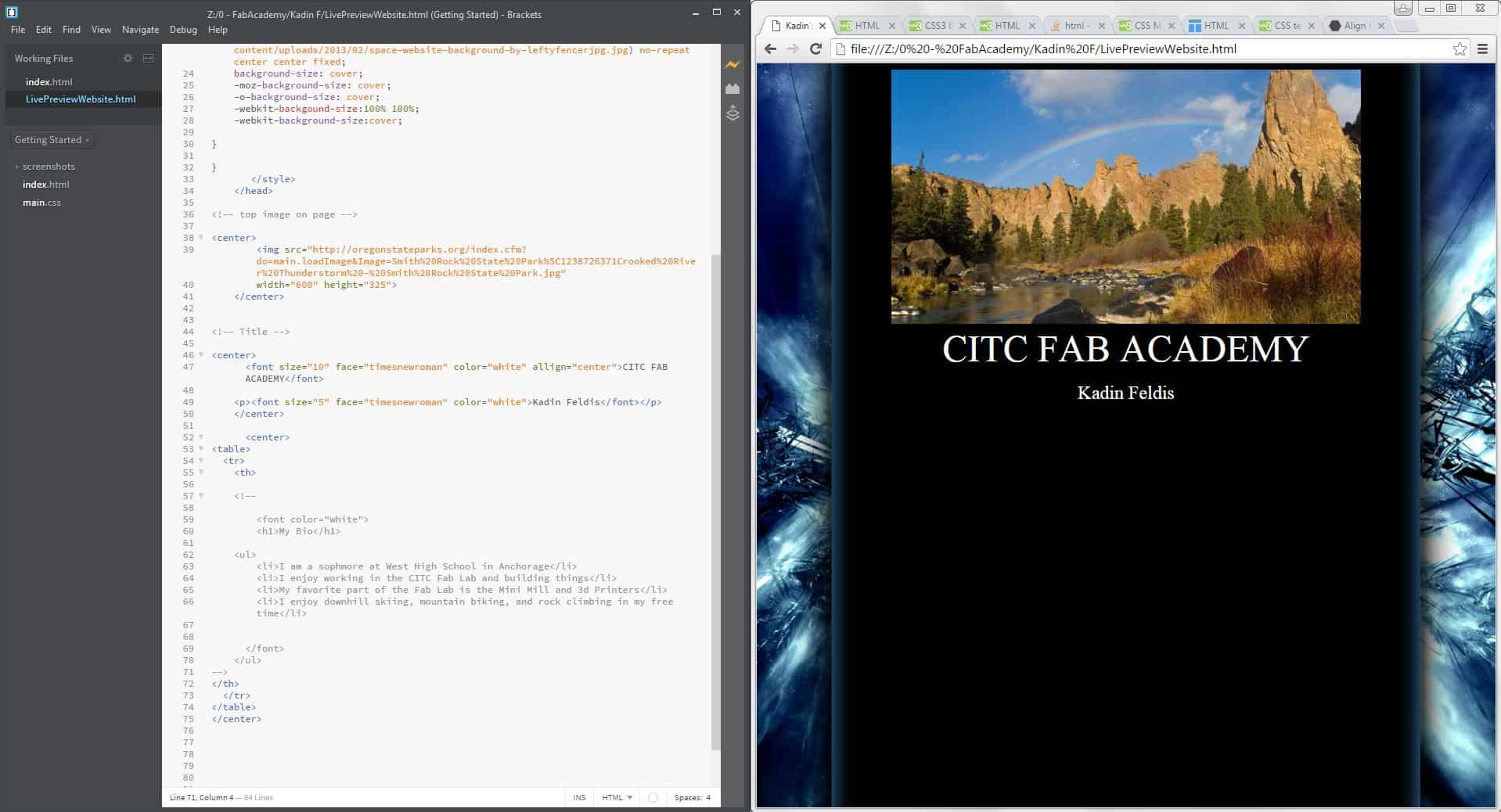
This is the first project I've done as a part of the Fab Academy class. I started to learn how to design and build a website in HTML. I used Brackets to explore other websites in HTML and learn how they format pictures, allign paragraphs, and create menus. From there I started my own website and utilized some features I liked from other websites to create what has become my Fab Academy webpage. I liked using Brackets but found that it takes longer than I would like do a simple things like adding pictures, linking videos and making anchors. I wanted to explore other options that would make basic tasks such as importing pictures more automated to speed up my website creation and editing in the future. Steven, who works at the CITC Fablab suggested I try Dreamweaver. |
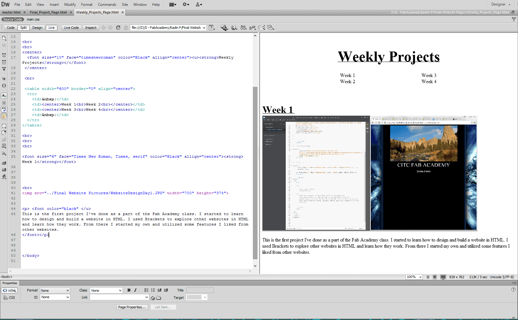
I decided to switch to Dreamweaver for its improvent interface and multipage website support. Dreamweaver makes it easy to preview your website as you write your code, it also has some very neat features that allow you to quickly and accurately link images from your computer to your website saving you time when making large websites with lots of images and videos. I started expanding my website and added multiple pages in order to make it easier to find things on my webpage. I used some of the more basic methods for creating menus and in-page links I had seen while looking at other web pages in brackets to put the finishing touches on my webpage. When I was finally satisfied with my basic website outline I moved on to the next step, setting up Git so I can push my website to the Fab Academy repository. |
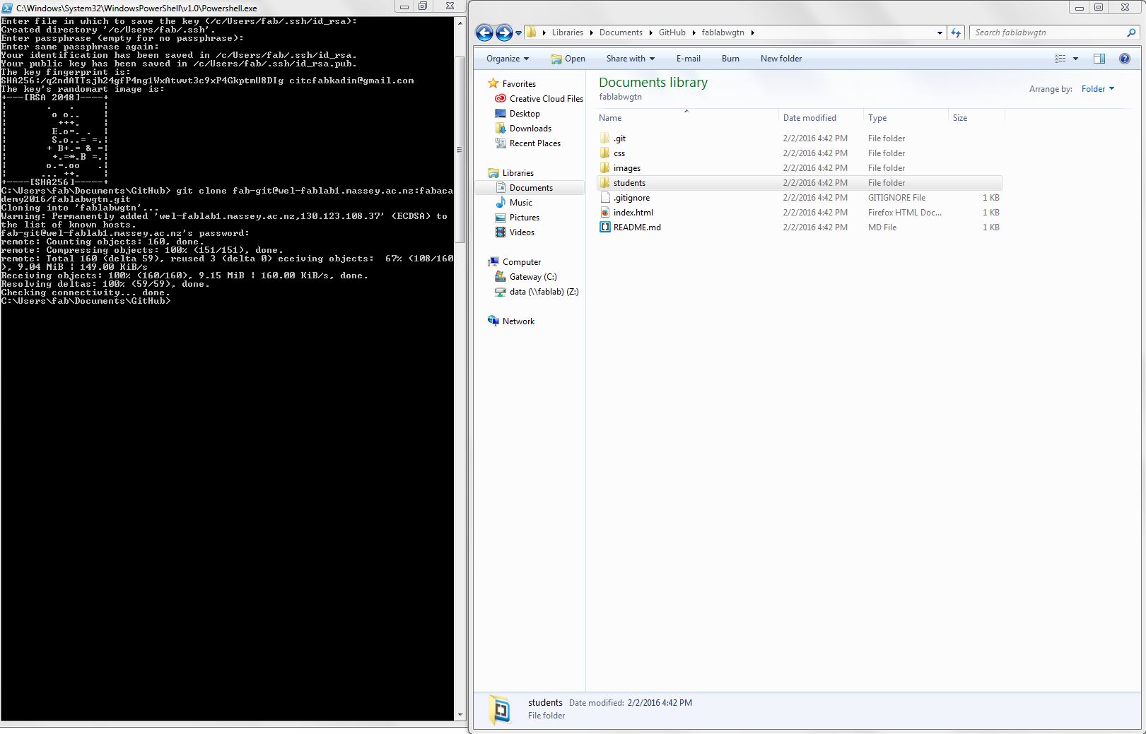
The first step in getting ready to push on Git for me was setting up my SSH key. After that, with the help of others, I was able to push my first documents(including my website) so that they could be accessed elsewhere, and my website could be published. |
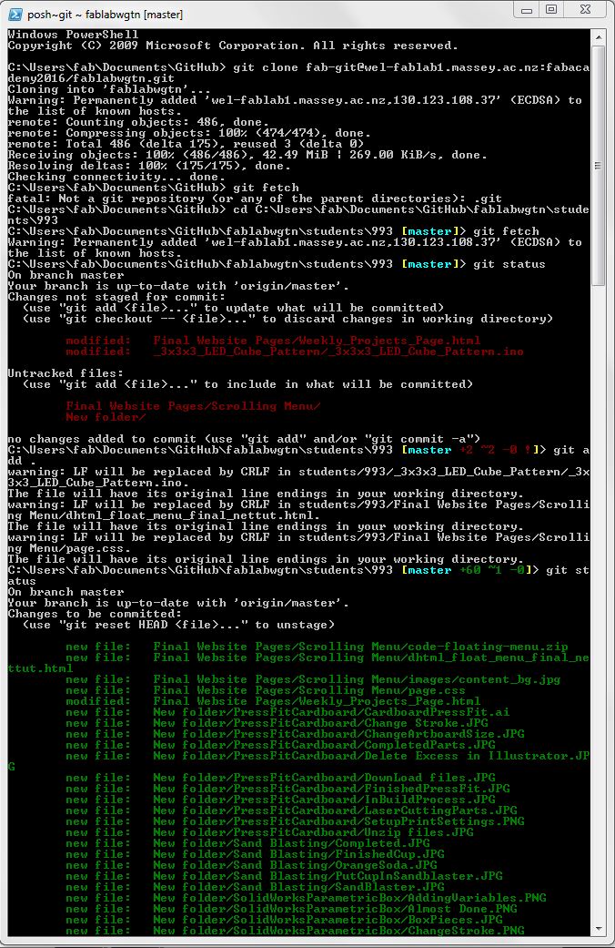
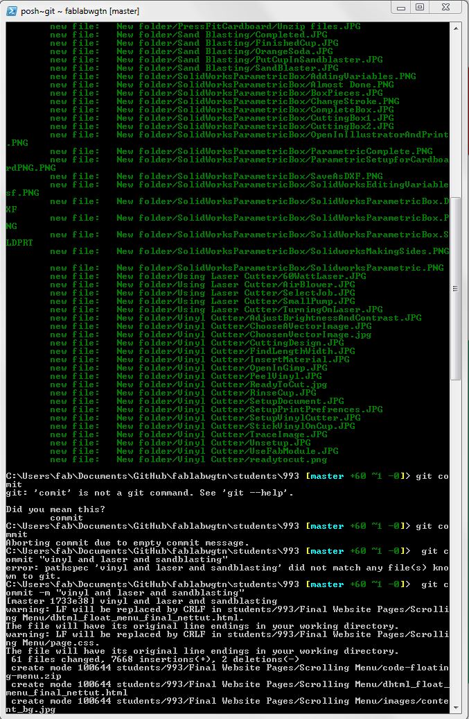
After setting up my SSH key I was ready to do my first GIT push. The pictures above show all of the terminal work I did to accomplish that. The steps are as follows. 1."git fetch" to check the repository 2."git pull" to update your local files 3."git status" as Steven puts it "see what's up" 4."git add" to add files you want to push 5."git status" again see whats up in the Git world 6."git commit -m "baldlafjdsf;lkas" create your commit and totally name it something creative and helpful for later on 7. "git push" to push 8."git fetch" to merge commicts into the master. 9."git status" to agian "see what's up" and make sure your commit went as planned. |
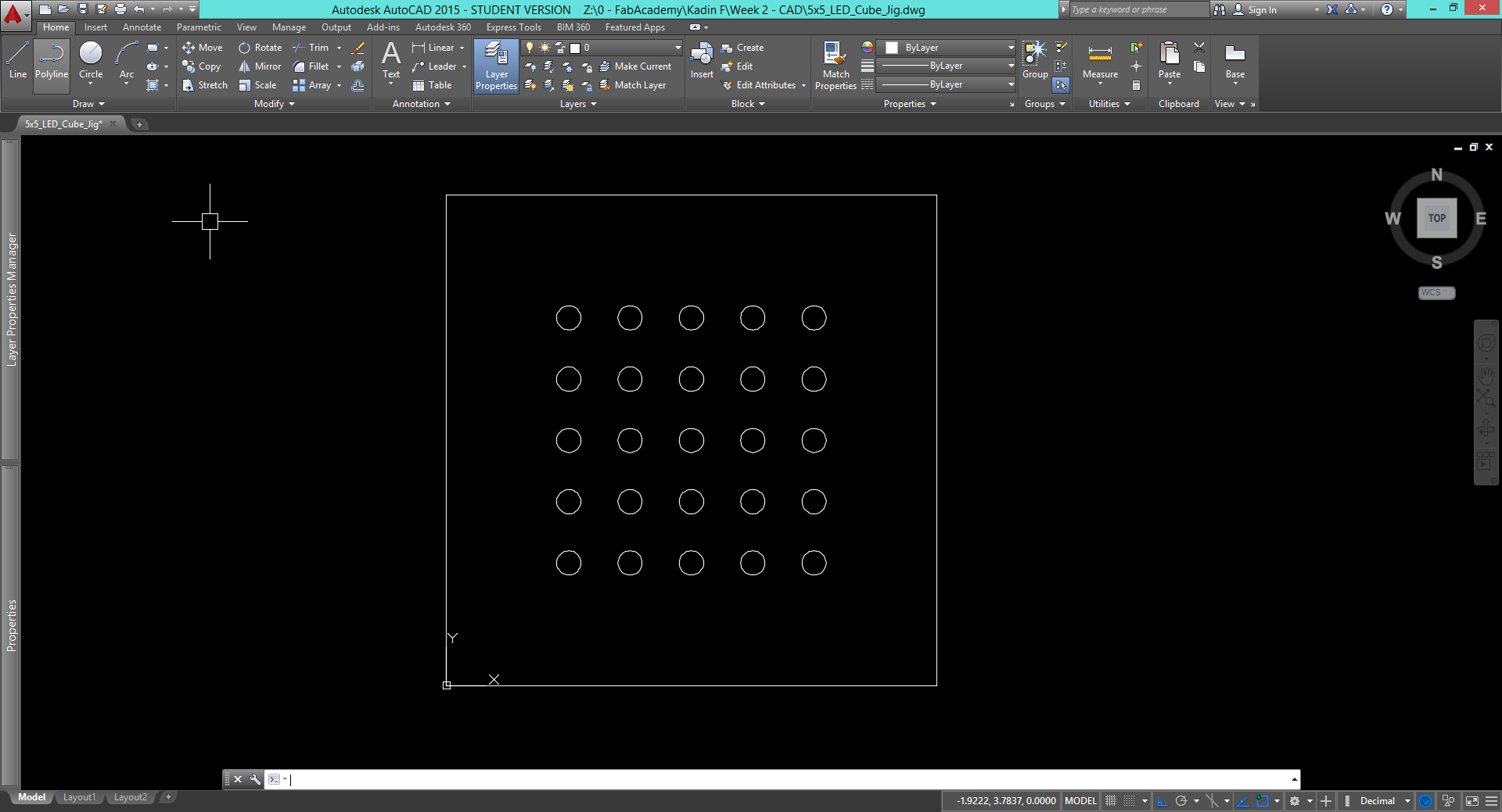
I started my 2d design this week in AutoCAD(although I plan to try out some different, open source softwares). The drawing above is a jig for soldering my LED cube together. It is a simple 4" square with a pattern of 5mm holes. When I assemble my LED cube I will place a 5mm LED in each hole so the cathode and anode pins are facing up. I will then bend the anode pins 90 degrees so that each LED is connected to the next making one layer of the cube. I will need 5 layers for the cube to be completed. |
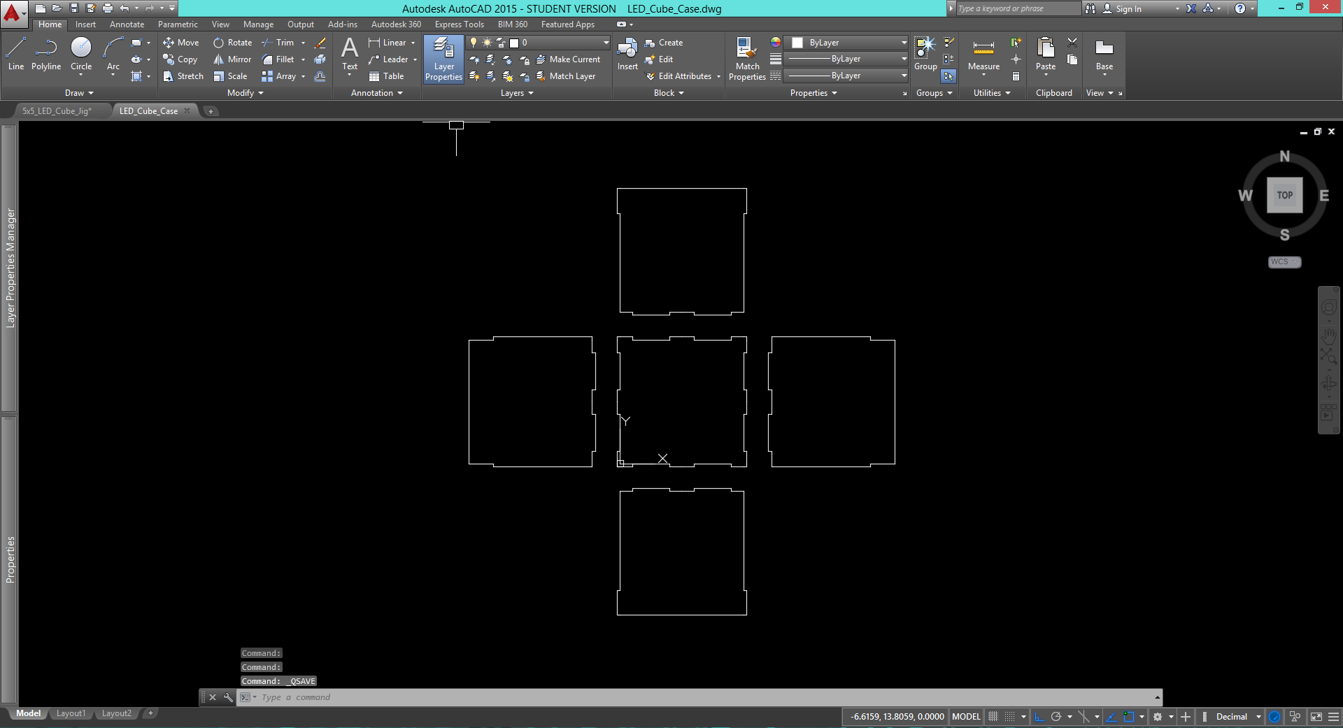
Next I designed the case for the LED cube in AutoCAD. I plan to laser cut it out of clear acrylic to show off the cube as well as protect it. The case will notch together and eventually set in a 3d printed base. The 3d printed base will hold a custom milled PCB designed in Eagle that will serve as the brain of the cube. In the future I will add variables to this design in AutoCAD. This will allow me to adjust the size of the physical box itself as well as the notchs. By doing this I will be able to easily change the box to work with any thickness of material and size of cube. |
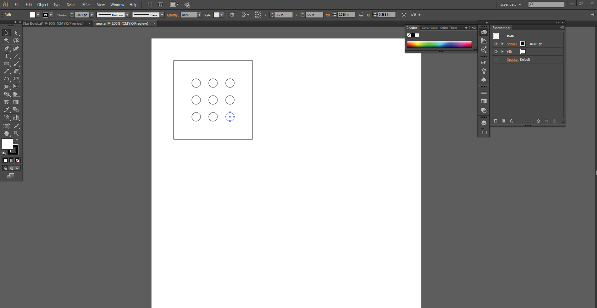
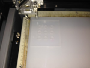
After designing the case and jig for my larger LED cube I decided to start on a smaller 3x3x3 LED cube. The first step was designing a jig for the smaller cube, so I tried out Adobe Illistrator. I made a 4" square and added nine 10mm holes for the LEDs to sit in. While using Adobe Illustrator I noticed a few key differences between it and AutoCAD. The main difference is speed, in Illustrator it takes much longer to design a simple part. This is mainly because of the keyboard shortcuts available in AutoCAD. Next I will laser cut my part desgined in Illustrator to make a mini model of what my final project might look like. |
Above is a video outlining the basic process for creating a drawing in AutoCAD. The thing that I like most about AutoCAD is the speed at which you can do simple tasks once you before proficent. There are lots of keyboard shortcuts and with some practice you can do almost everything with the keyboard saving you time on large projects. The most time is saved by eliminating the need to sort through menus to find the exact tools and functions you would like. |
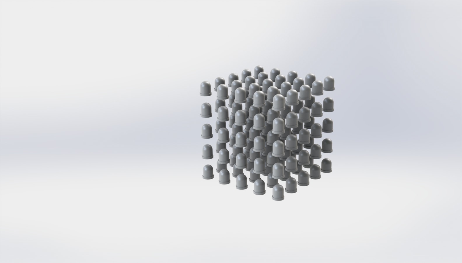
For 3d design this week I used SolidWorks. I created a three dimensional cube of 125 LEDs and used the rendering software to create a decent quality photo. This model has helped give me an idea of the space I will have to solder the LEDs together. I think based on the model I will definetly opt for small 5mm LEDs rather than the 10mm LEDs I used in my SolidWorks model. This will give me more spacing for wiring and make it easier to see the lights on the inside of the cube. |
Above is a video outlining the process for creating a 3d pattern such as the LED cube render above using Solidworks. Solidworks is my go to 3d design program do to its plethora of features and easy to use, logical interface. It provides everything from basic geometric design to advanced surface modeling and parts testing. |
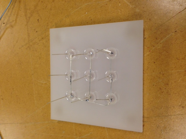
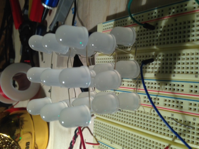
The photos above show my process for creating a mini 3x3x3 LED cube for this weeks CNC cutting. I laser cut the acrylic jig and then placed 9 LEDs in it. I then soldered the negative leads together, and repeated the process 3 times. After soldering the three layers together I plugged the cube into a breadboard. While I was soldering the cube I began to further recognize the challenge a larger cube would present. I now know that I should definetly use 5mm LEDs instead of 10mm LEDs so that I can solder the leads without running into the LEDs themselves. Also, if I want to use RGB LEDs, which I do, I is going to be very difficult to solder all of the leads and keep the cube looking clean and proffessional. |
Just a note. I went down a small rabbit hole in the next few pictures making a prototype mini LED cube, so click here if you want to skip down to the rest of my CNC work. |
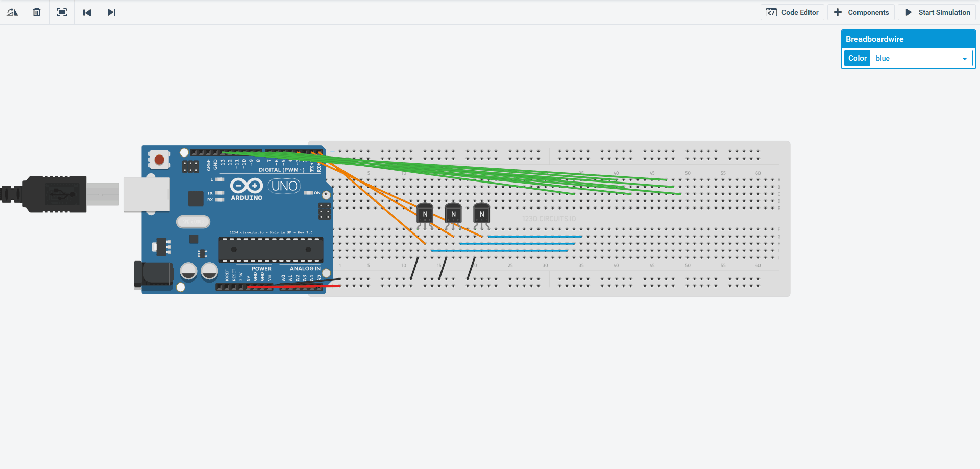
To design the circuit I used to control the cube I considerd using 123d. I played around with it and designed a simple circuit as seen above. The orange wires are outputs that control NPN transistors. Those transistors output through the blue wires which control the ground for each layer of the LED cube. The 9 green wires each control a positive column of 3 LEDs. The issue is 123d is limiting in some regards, and just to slow to be functional for large complex circuits. It is limited to 2d so it is imporssible to make a 3d looking cube, also the work area is very limited for a project the size of a cube. Another interesting note for others considering 123D, the shift registers in particular do not function well. This is because of the manufacturers recommended "max" current. Shift registers such as the 74HC595 have a very low current and voltage limit which 123d adheres to. In the real world the max current and voltage for the chips are many times higher than spec allowing them to be used in circuits such as LED cubes, but 123d will simply give you an error if you push these limits. In the end I just used a breadboard and stuck some wires in it, but for my final, more complicated LED cube I will use Eagle. |
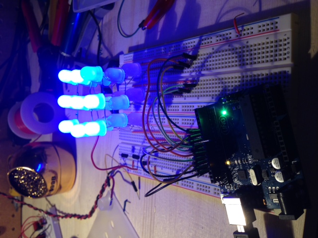
Above is a basic animation I have been working on. It is displayed on an Arduino driven 3x3x3 single color LED cube and uses very basic software. For my final project I plan to expand to a bigger cube and hopefully RGB LEDs, because who doesn't like more color. The issue I am thinking about now is what type of ICs to use to drive the LEDs. I am thinking about either 74HC595 shift registers(maybe the ones from Adafruit because they sell a higher current rated one) or maybe Max7219(or the newer 7221). The shift registers would be easy to use and there is alot of information online on using these, but they would require more on the software side because they are only a latch and do not do any multiplexing work for you. On the other hand there are the Max7219 LED drivers, these would be good because they are LED drivers and take care of alot of the multiplexing load your microprocessor would have to otherwise handle(I will probably use an Atmega168 or 324). |
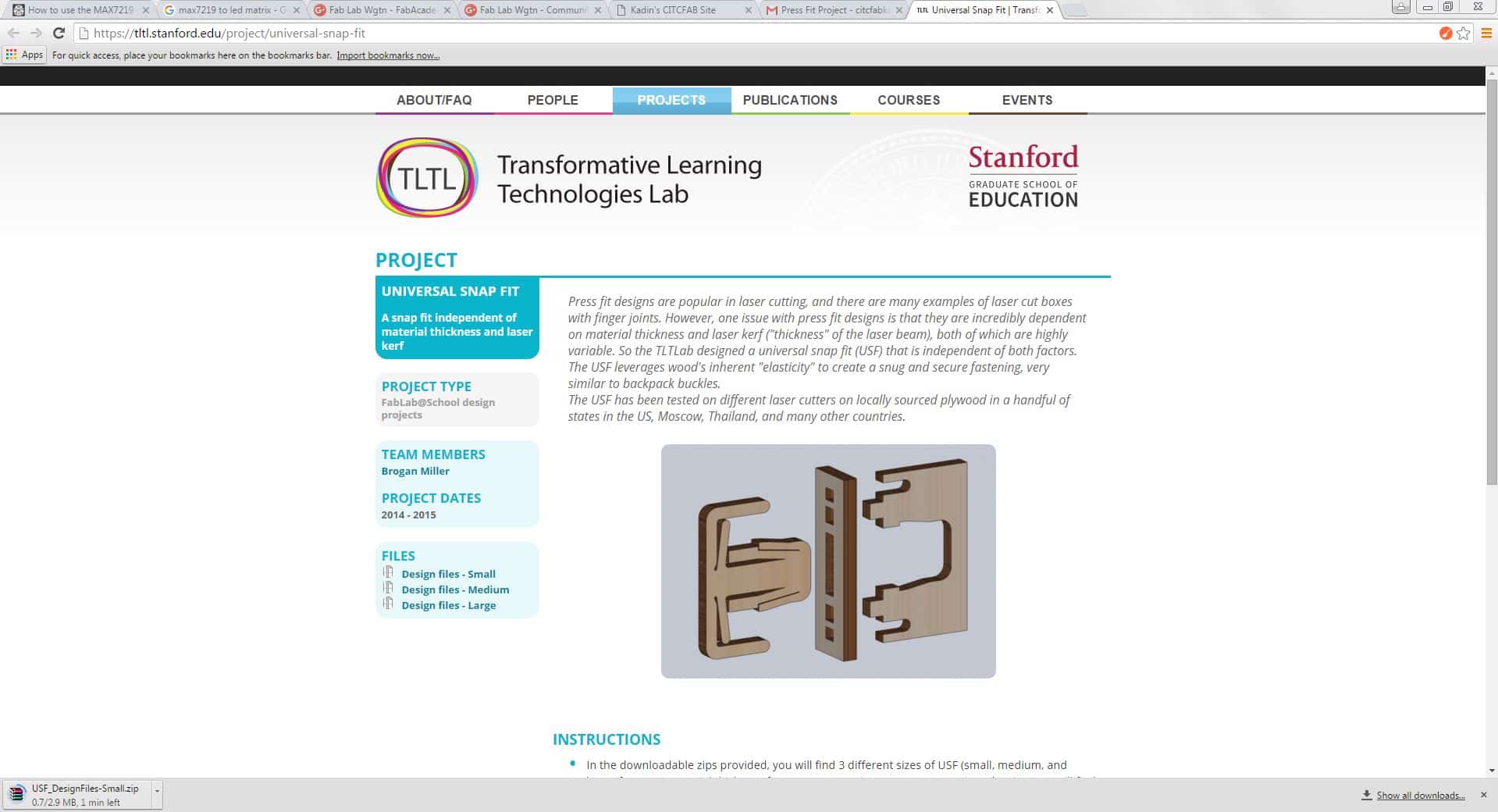
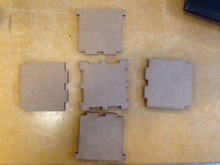
For my first press fit object I downloaded a part from TLTL(Transformative Learning Technologies Lab) Stanford. This is a simple part that would allow me to get familiar with the process of making and assembling press fit structures so I could make my own. |
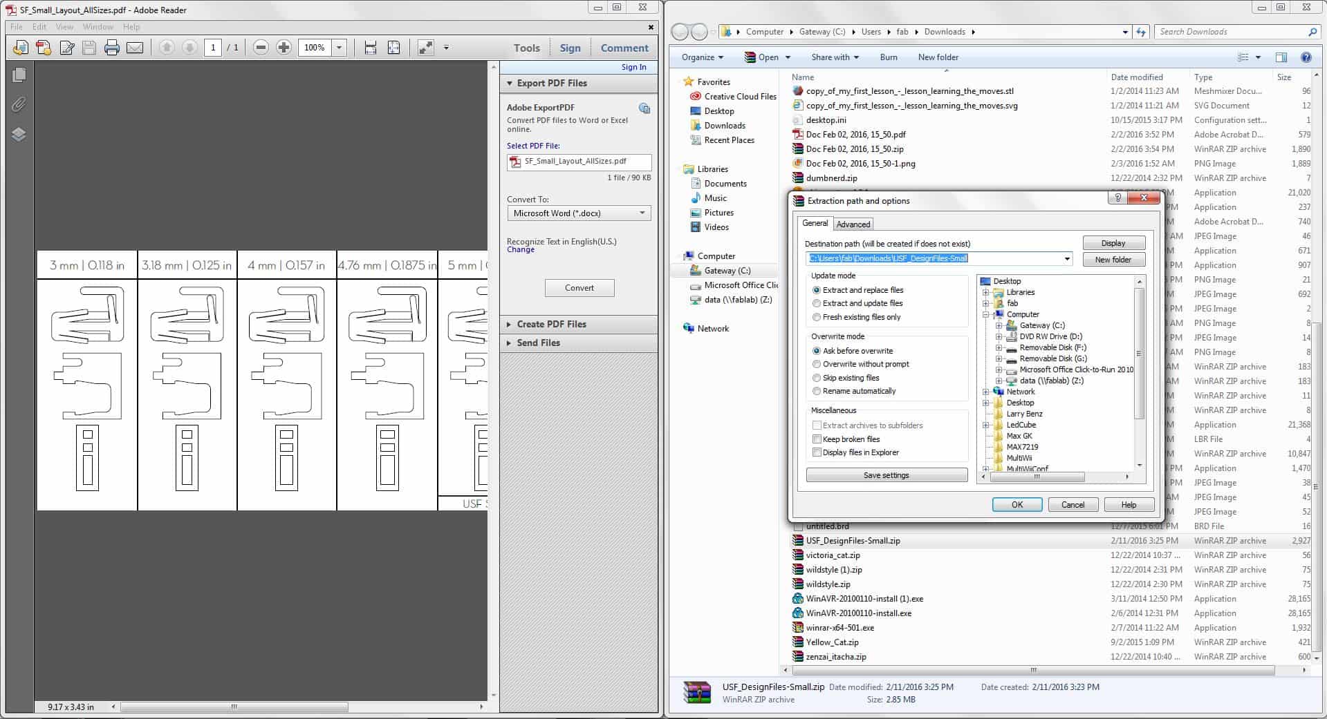
After downloading the files from the TLTL Stanford page I unziped them and opened the PDF file. After opening the PDF file I found that there were multiple sizes for different material thickness, so I needed to select one. |
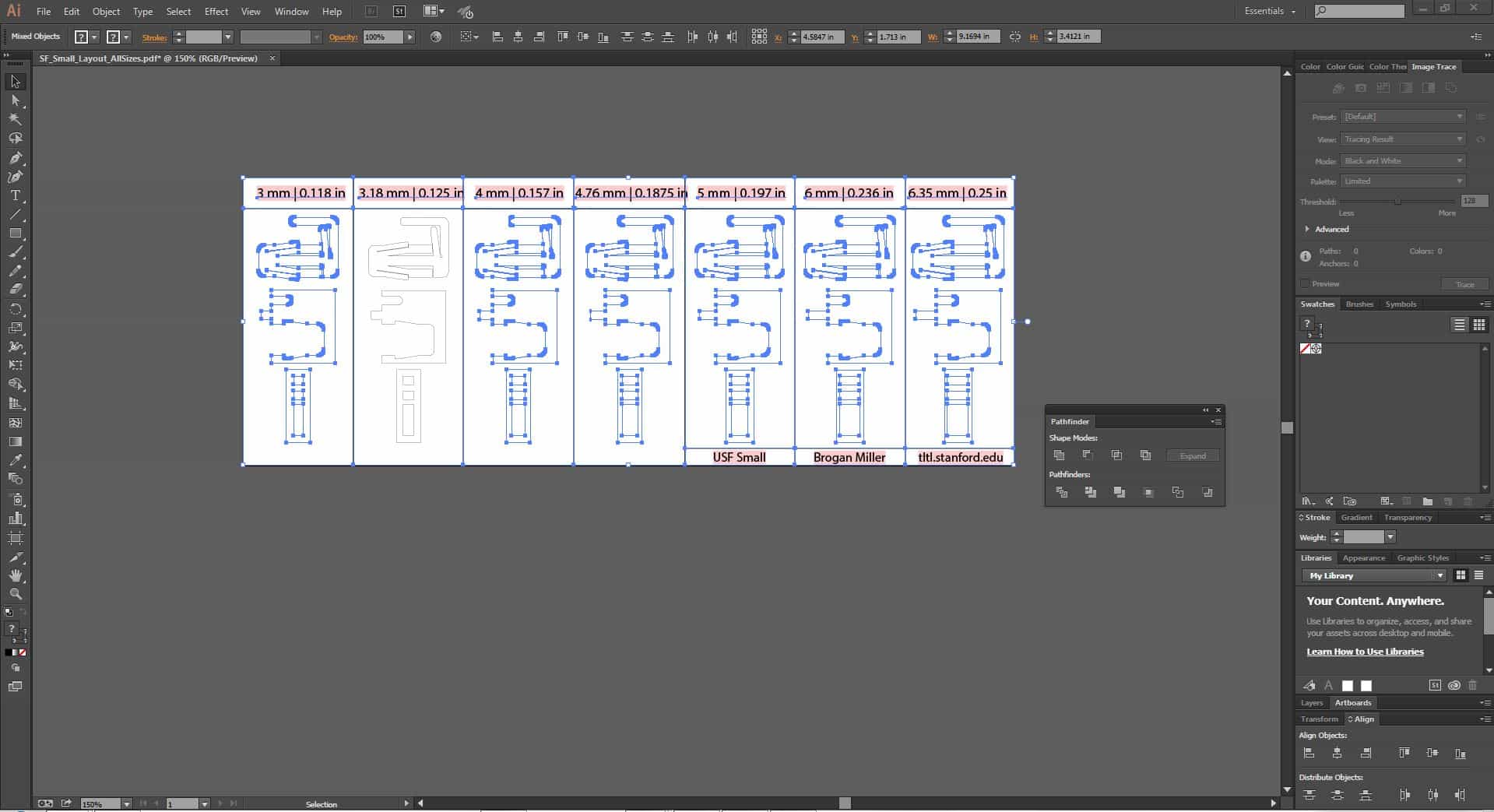
I opened the PDF and used my new skills from last week to delete all of the other designs that I did not want. |
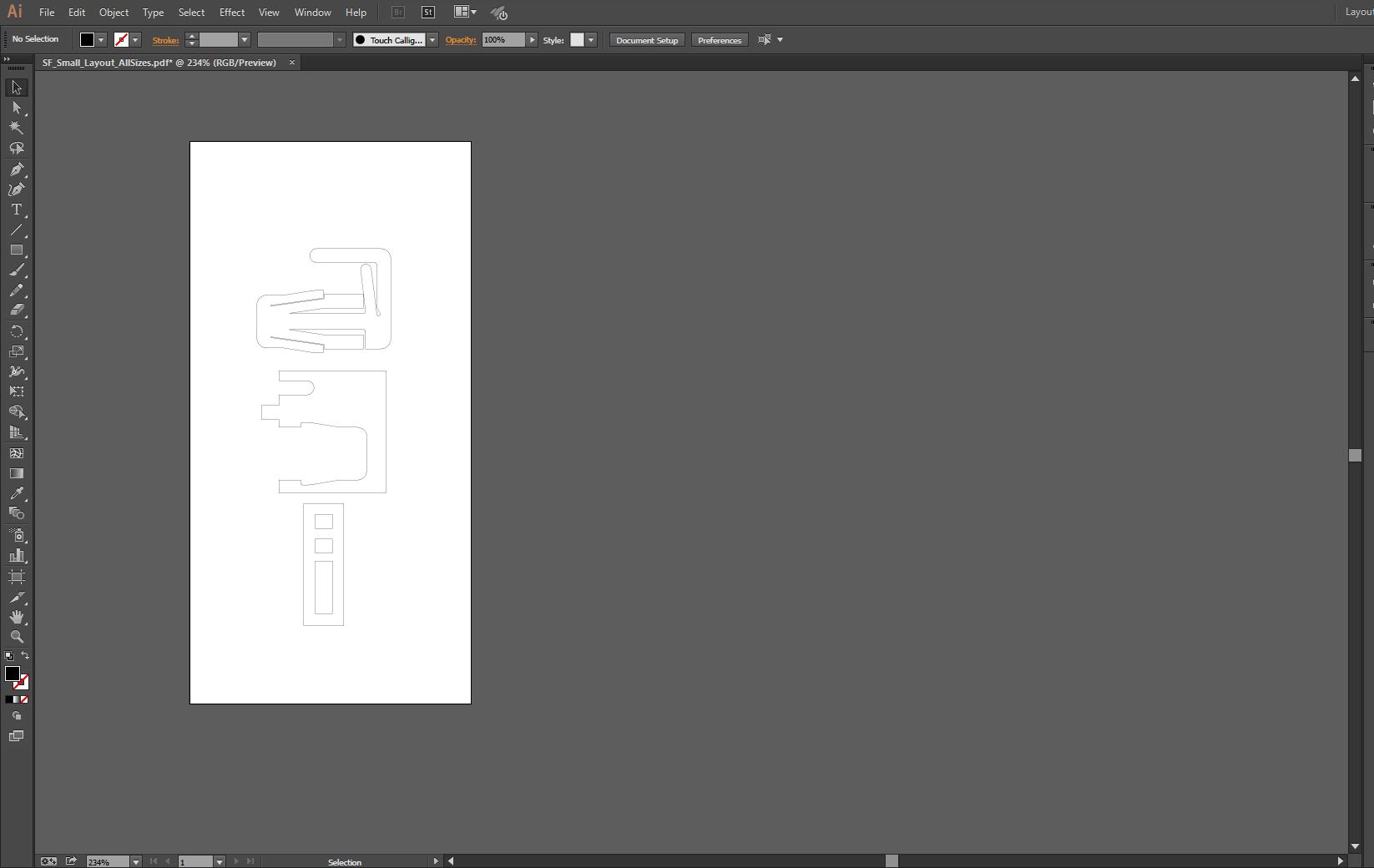
After deleting the other designs I adjusted the artboard(workspace) to fit the single design. |

Next I adjusted the line thickness/stroke from the default 0.072pt to 0.001pt so that the laser could read the lines. |
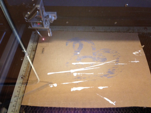
Using a scrap piece of cardboard I cut out the parts downloaded from TLTL and adjusted on Adobe Illustrator. |
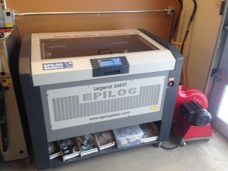
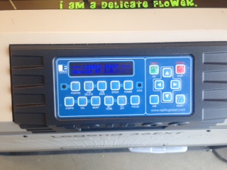
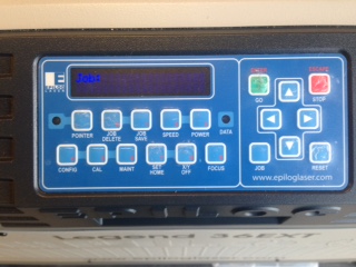
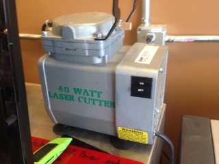
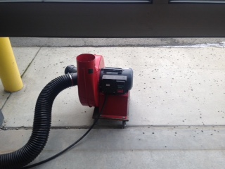
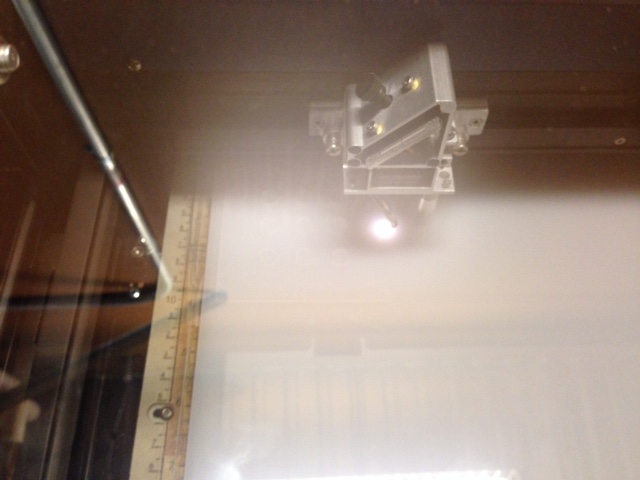
Setting up the laser cutter is pretty straight forward. On the left side of the laser cutter there is an on off switch. After you turn that on the laser will initialize and a menu will appear. Before selecting your file the small pump, with green letters in the picture above, must be turned on. Then the blower unit is placed outside and turned on to vent the fumes. Finally select the job and the cutting will start. |
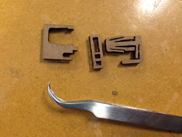
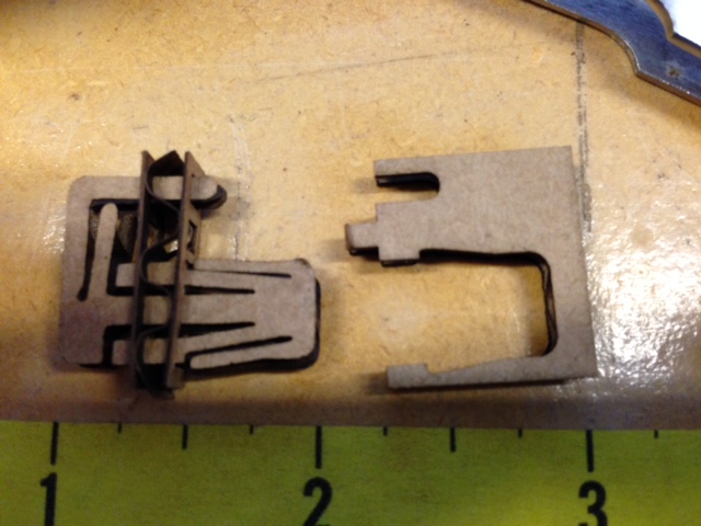
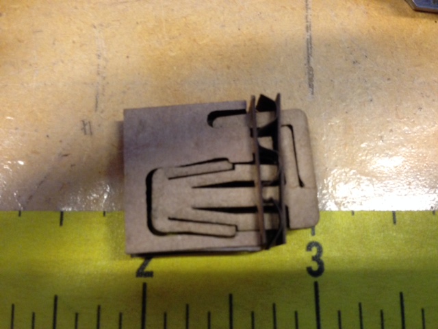
After cutting out the cardboard pieces, I used tweezers to remove a few little pieces of cardboard still filling some of the slots. Then I slid the parts together. This took alittle work since I was using an imperfect scrap of cardboard but in the end I got them together and made by 1" by 1" press fit cardboard structure. |
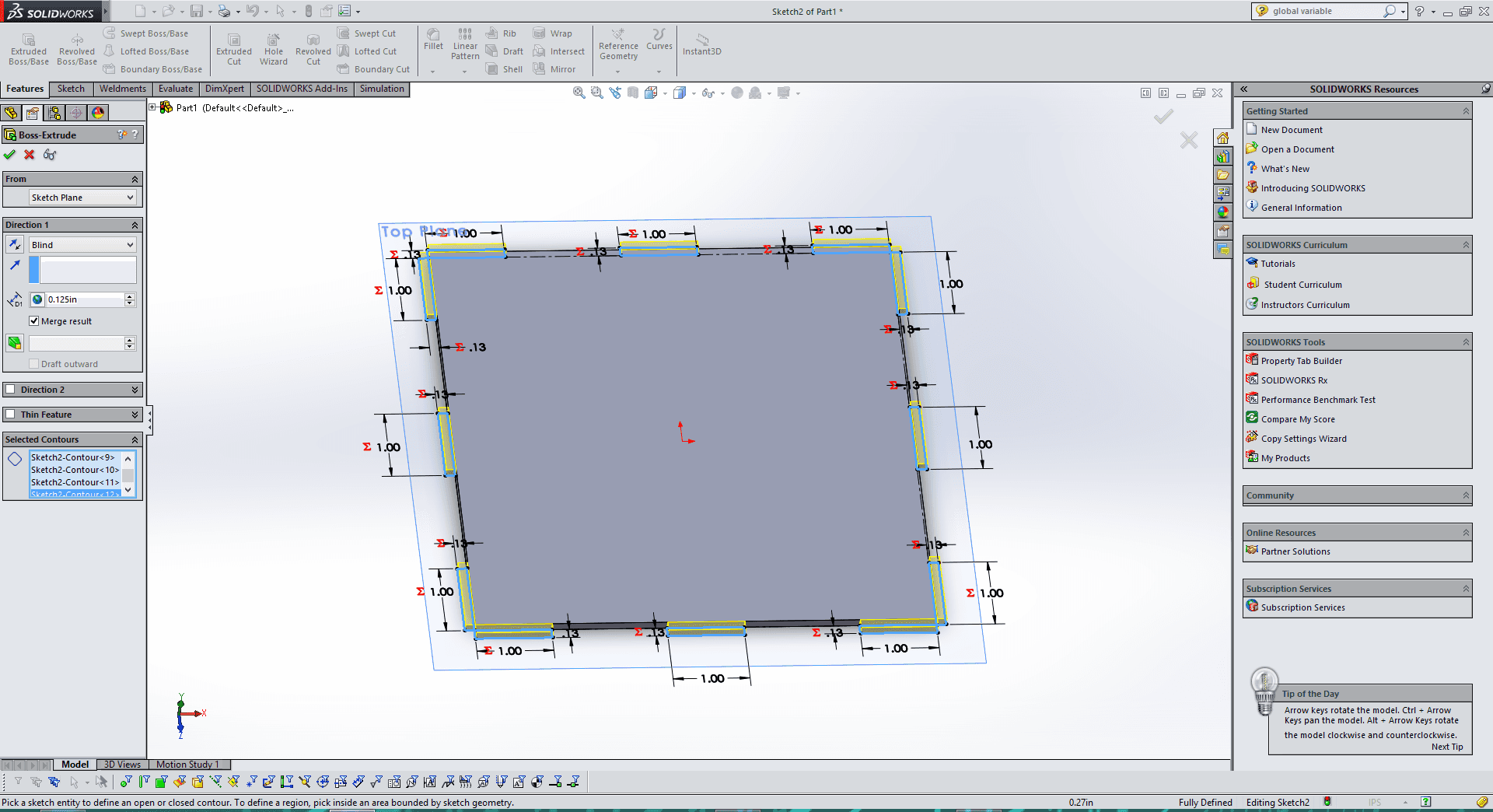
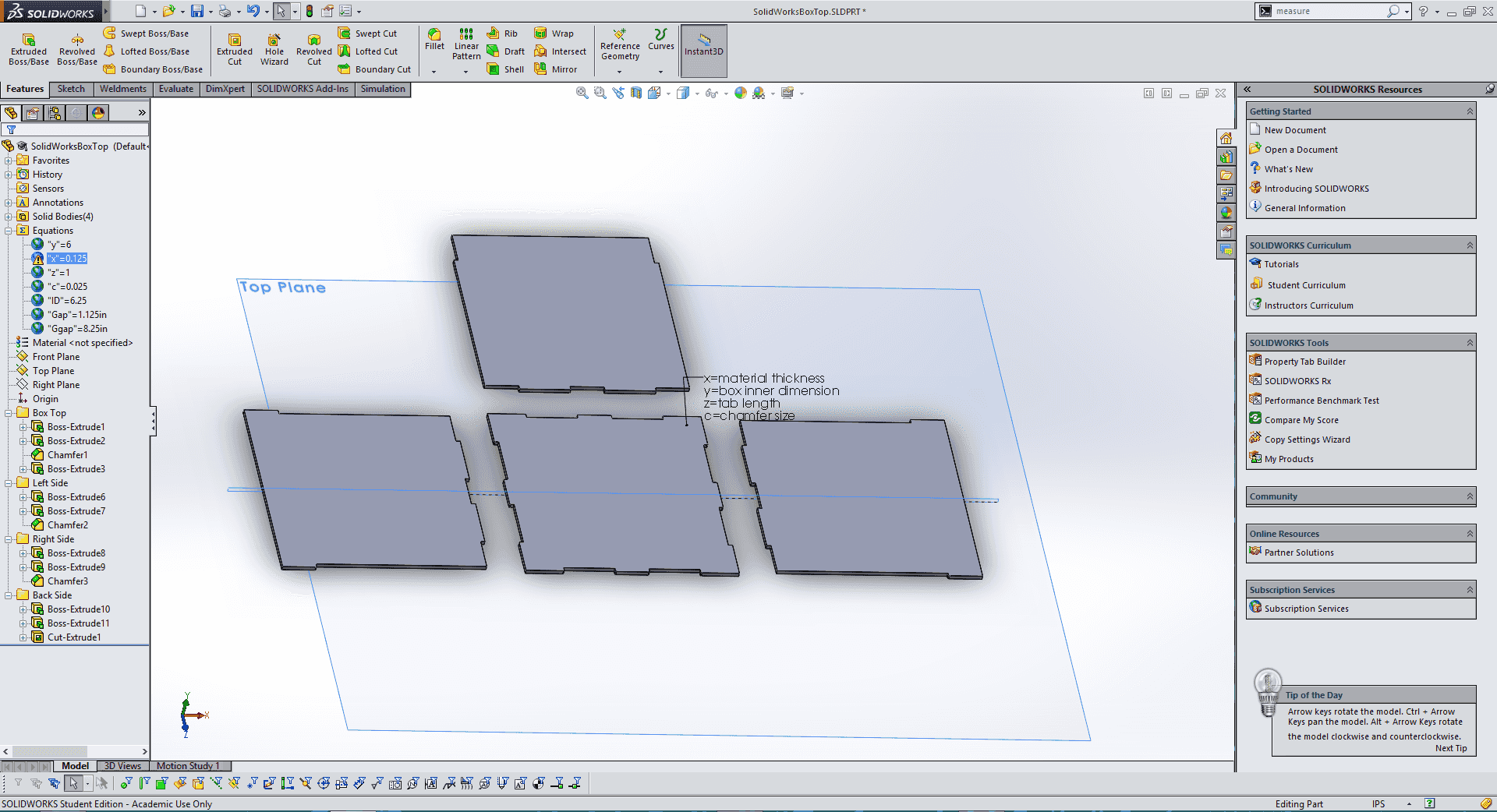
For my next project I decided to create a parametric box design in Solidworks. I wanted to have a file that I could edit for any size material to create any size of box. Here is a link for the Solidworks file for anyone who would like my SolidWorks Parametric Box file. |
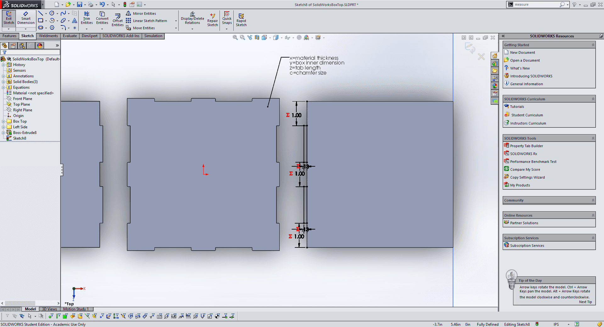
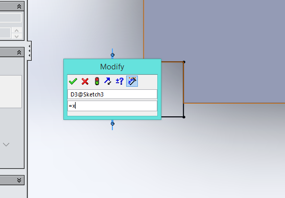
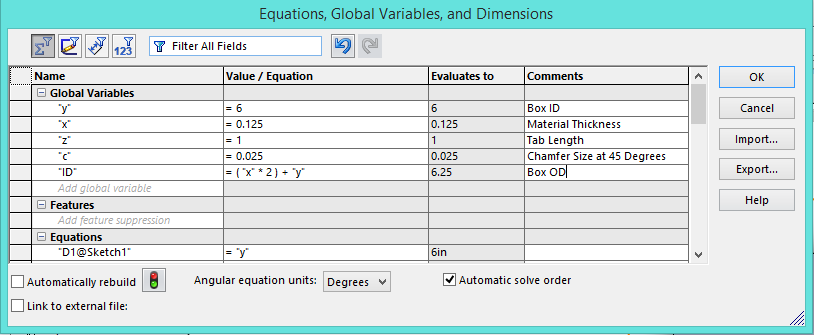
When designing the box I added a number of variables that can be changed to define the box. These global variables are present in all of the sketches that make up the file. Y is the inner dimension of you box. X is the material thickness. Z is the tab length. C is the chamfer size at 45 degrees and just to mix things up ID is the OD or outer dimension of the box. All of these can be modified in the downloadable file in the link above by going to Tools>Edit Varibales. |
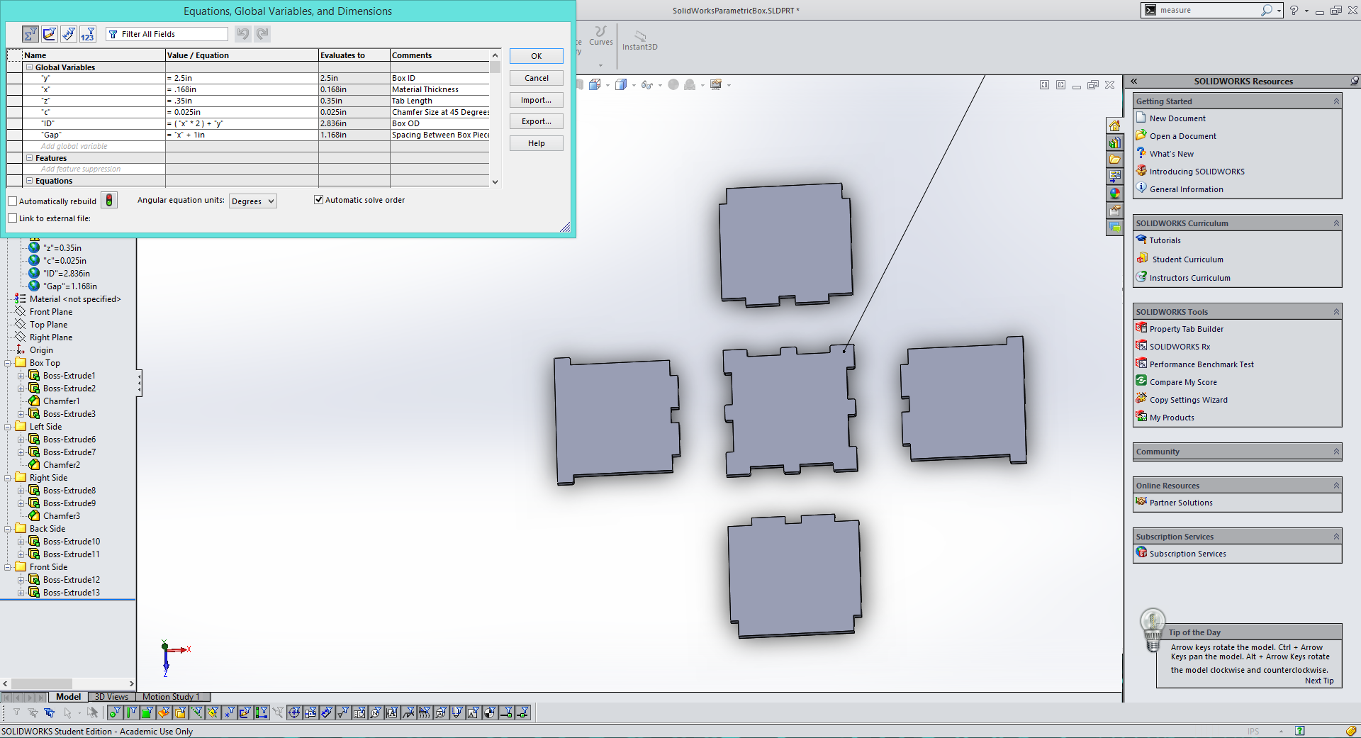
The box has 4 sides, so it has not bottom this is because I am going to use this file to create boxes for my LED cube project that will have its own 3d printed baseplate. I plan to add another file with a completed box for anyone who wants to use it. Once I was done with the box I changed the variables for my cardboard thickness and a 2.5" length/height. |
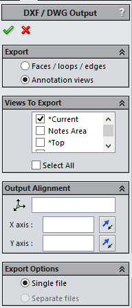
Next, I saved the Solidworks file with the variables set for my cardboard as a .DXF, this can be done by going to File>Save As>.dxf. Solidworks will then give you a menu as seen above, simply select "Top" and then hit the check mark to save the file. |
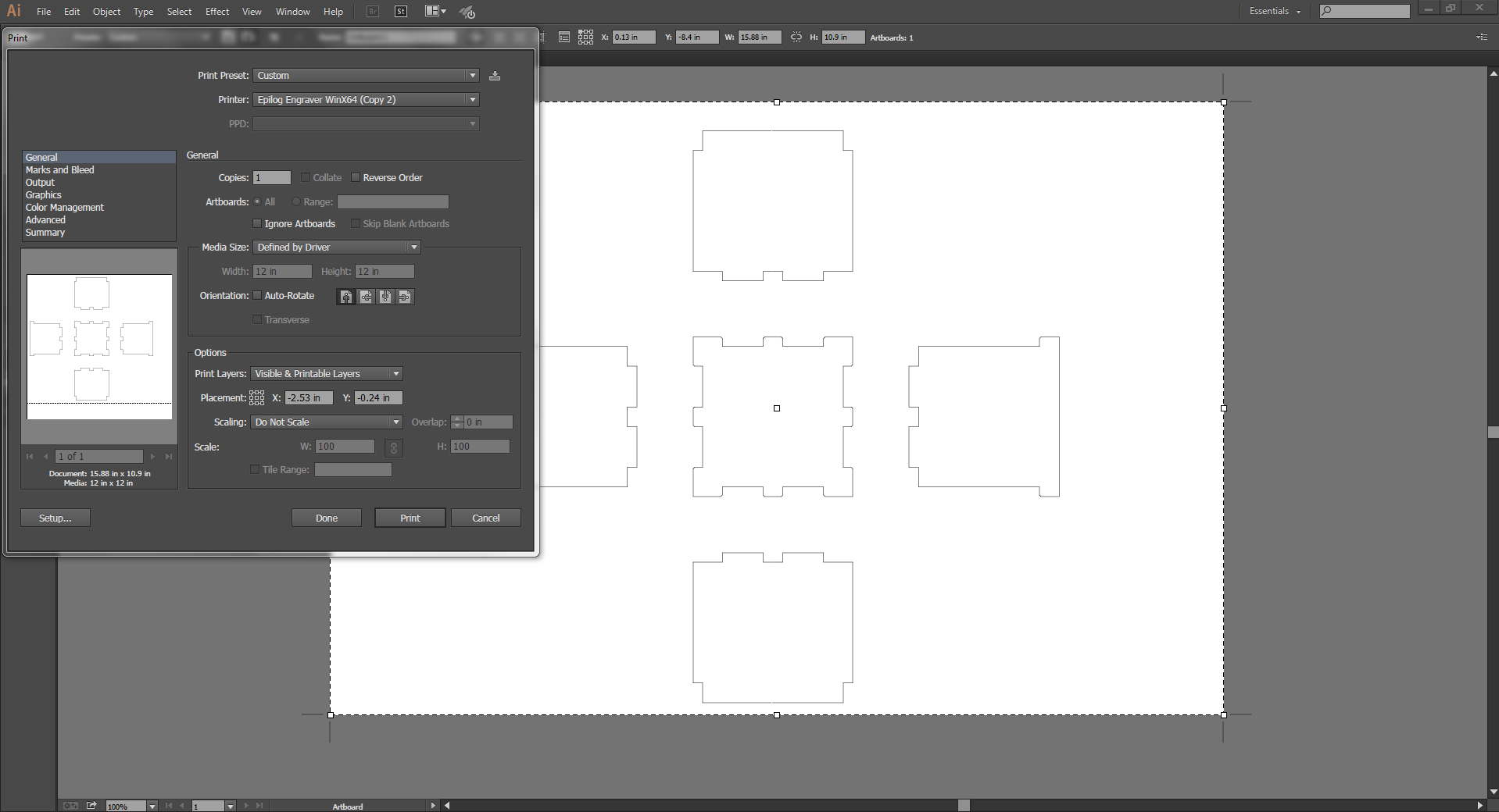
Finally, I opened the .DXF file I exported from SolidWorks in Adobe Illustrator so cut it. I changed the stroke/line thickness to 0.001pt and then hit print. |
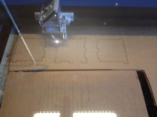
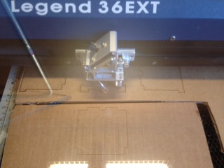
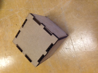
After the Epilog Laser Cutter cut out the pieces I pressed them together and my first press fit box of the class was complete. The only tricky part about cutting is when you are using scrap material, as I was, sometimes you have to spend a little extra time making sure your material lines up. |
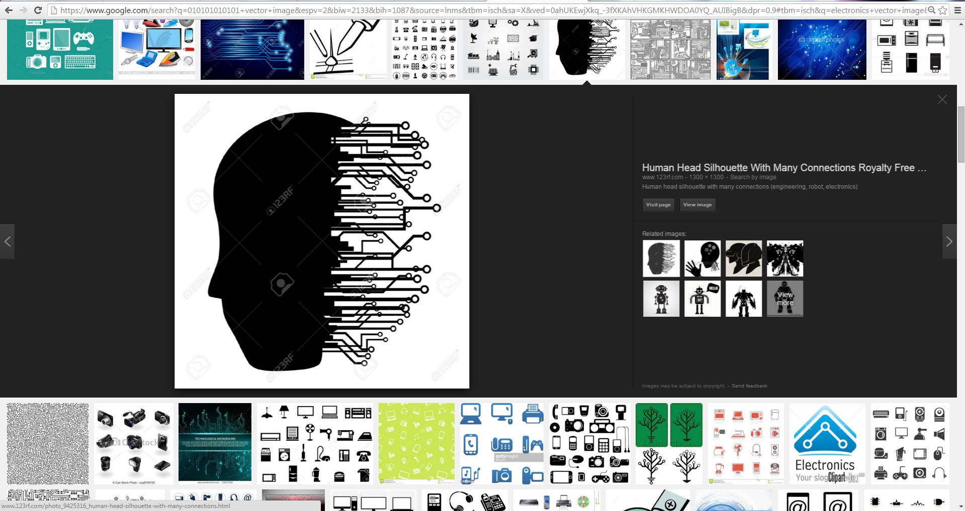
For my vinyl cutting project I found a vector image of a human head with some cool electrical connections attached. |
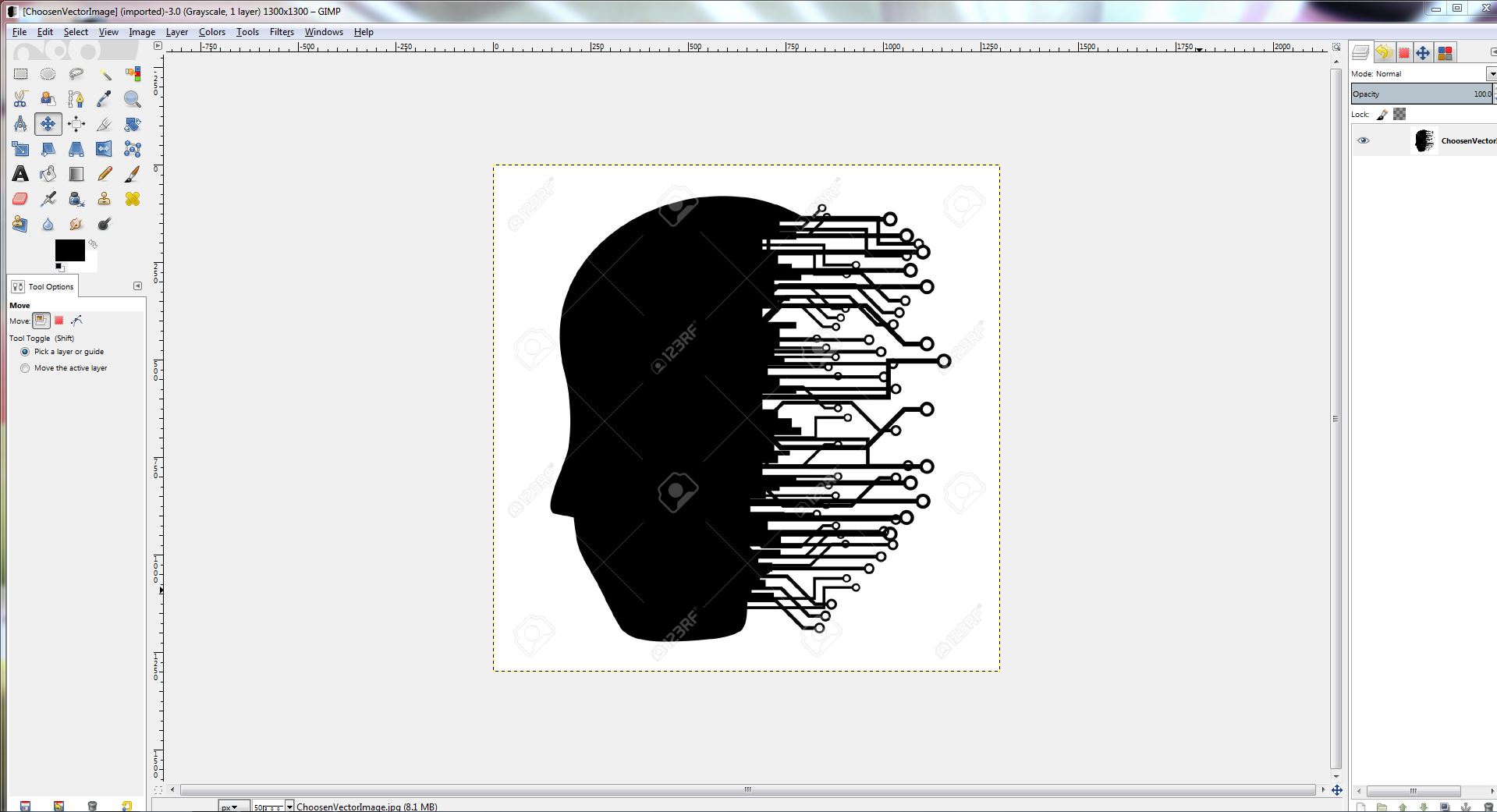
After downloading my vector image, I opened it in Gimp to get ride of the watermark. After that I opened the file in AdobeIllustrator and tracked the image, making sure to change the stroke to 0.001pt. |
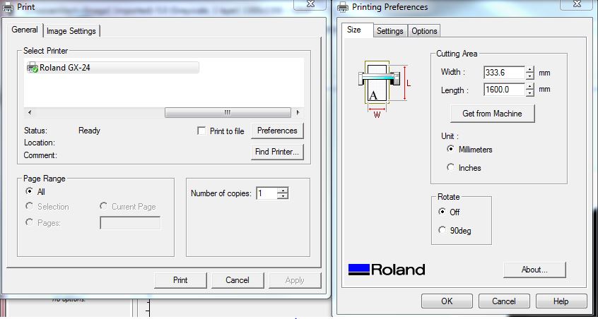
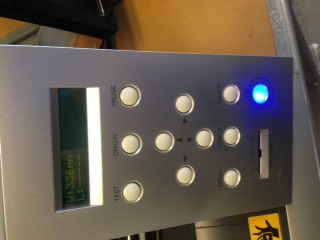
Finaly I hit print in Adobe, and adjusted the prefrences to pull the cut area size from the machine. Before this can be done the vinyl cutter must be turned on, and either Sheet, Role, or Edge selected. The machine will then measure your piece of vinyl. |
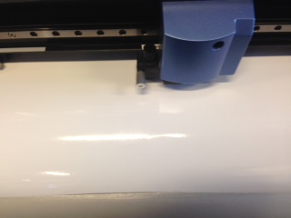
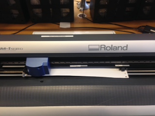
The vinyl cutter then cut out my downloaded design. |
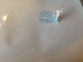
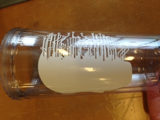
Once my (downloaded)design was cut I began the laborious process of peeling out my design. The process is made much easier by using a pair of tweezers, or simply don't select a design with lots of tiny details. Finaly once I removed my design I stuck it onto a plastic cup that I wanted to sandblast. One note, I decided to peel out my design and use it as a sticker in the sandblasting process instead of using the stencil. This is totally up to whoever is doing it but just keep in mind which area you want textured by the sandblasting. |
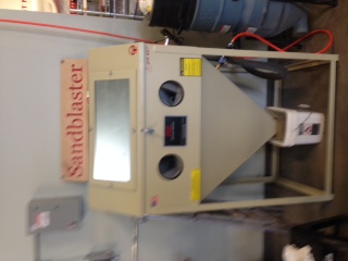
Since I had just finished vinyl cutting it seemed that sandblasting was the next logical thing to do. |
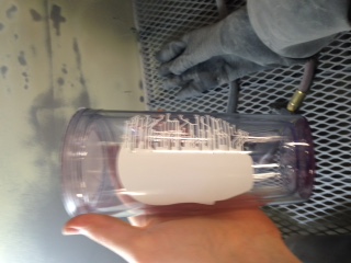
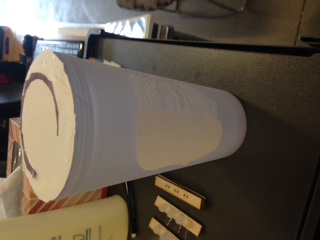
The sandblasting process is relatively simple. I took my plastic cup with the vinyl cut design and put it in the sandblaster. Making sure to close the lid tightly I turned on the light, filter, and air compressor. After that its just a few minutes of work with the sand gun making sure to texture all of the exposed plastic evently. After that I peeled of the vinyl and washing off the excess sand I had a nice new, custom cup. |
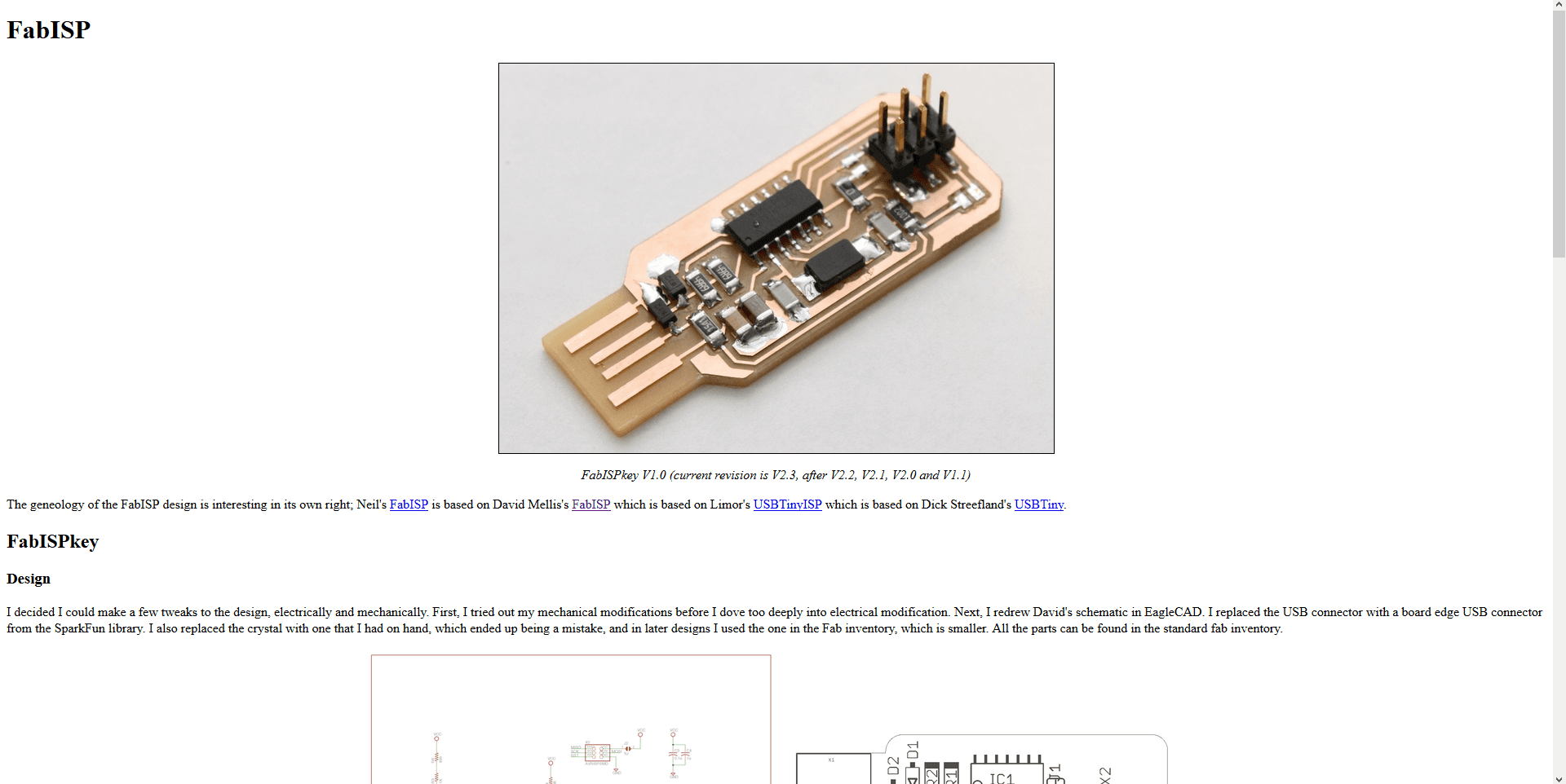
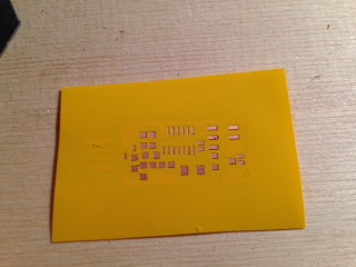
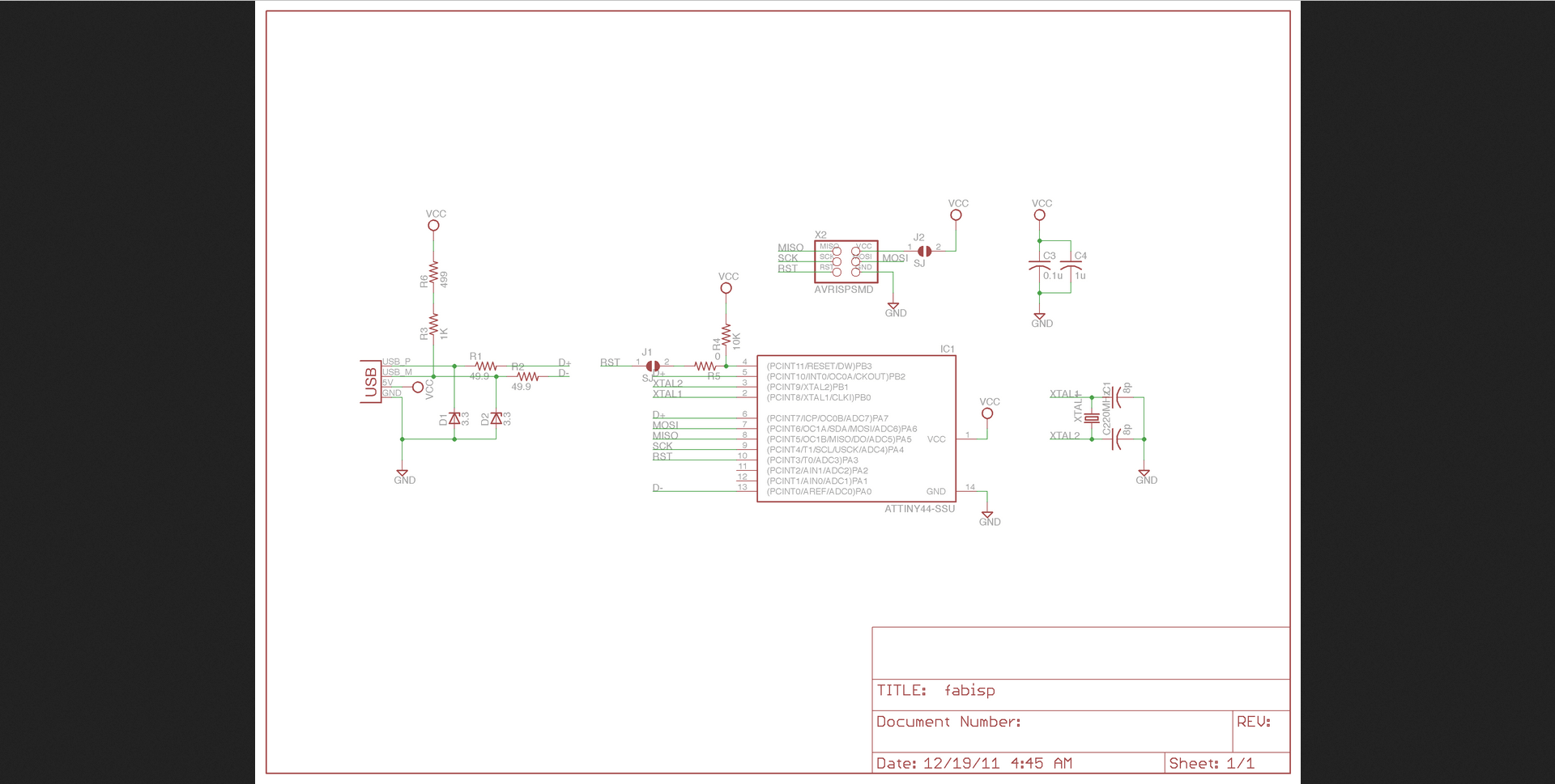
For electronics production I desided it would be fun to make a Fab ISP that could go on a keychain. This has been done before and I found I design online to use to create my first iteration. I downloaded the PNGs for the traces and outline. |
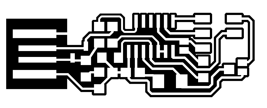
The traces I downloaded looked good, but one thing was missing that I will create myself and add a download link. That is, a stencil for applying solder paste before using a reflow station. |
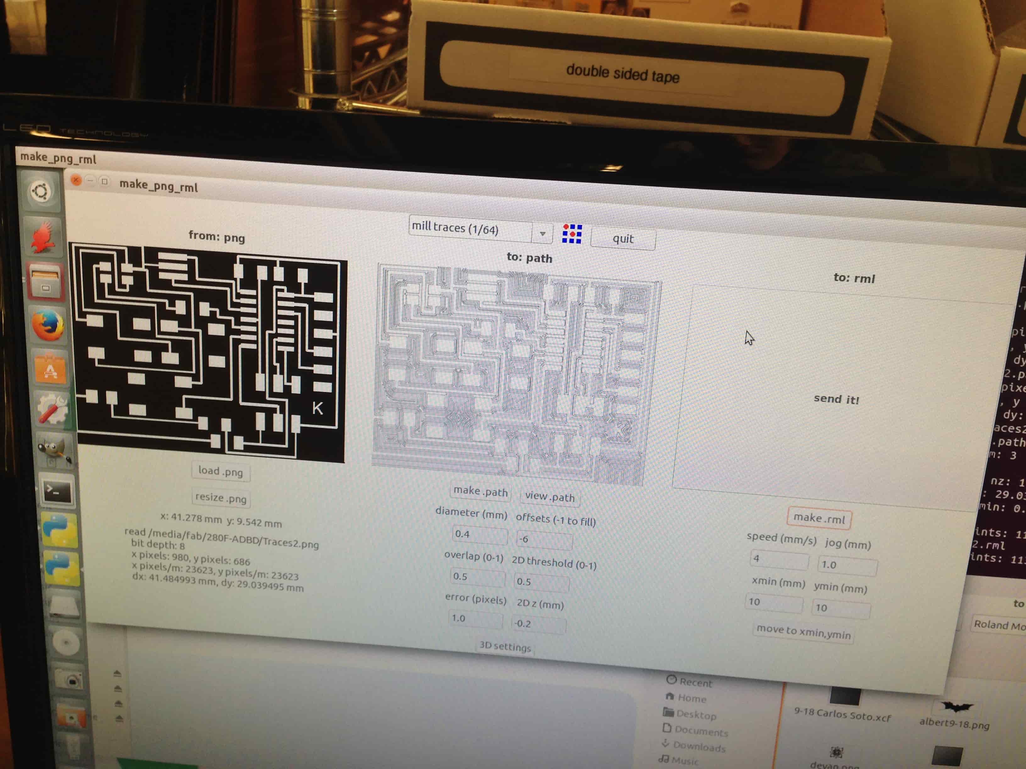
Using the Fab modules I opened the downloaded files for the Fab ISP(traces and outline). |
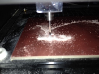
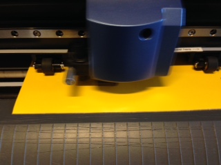
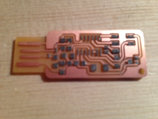
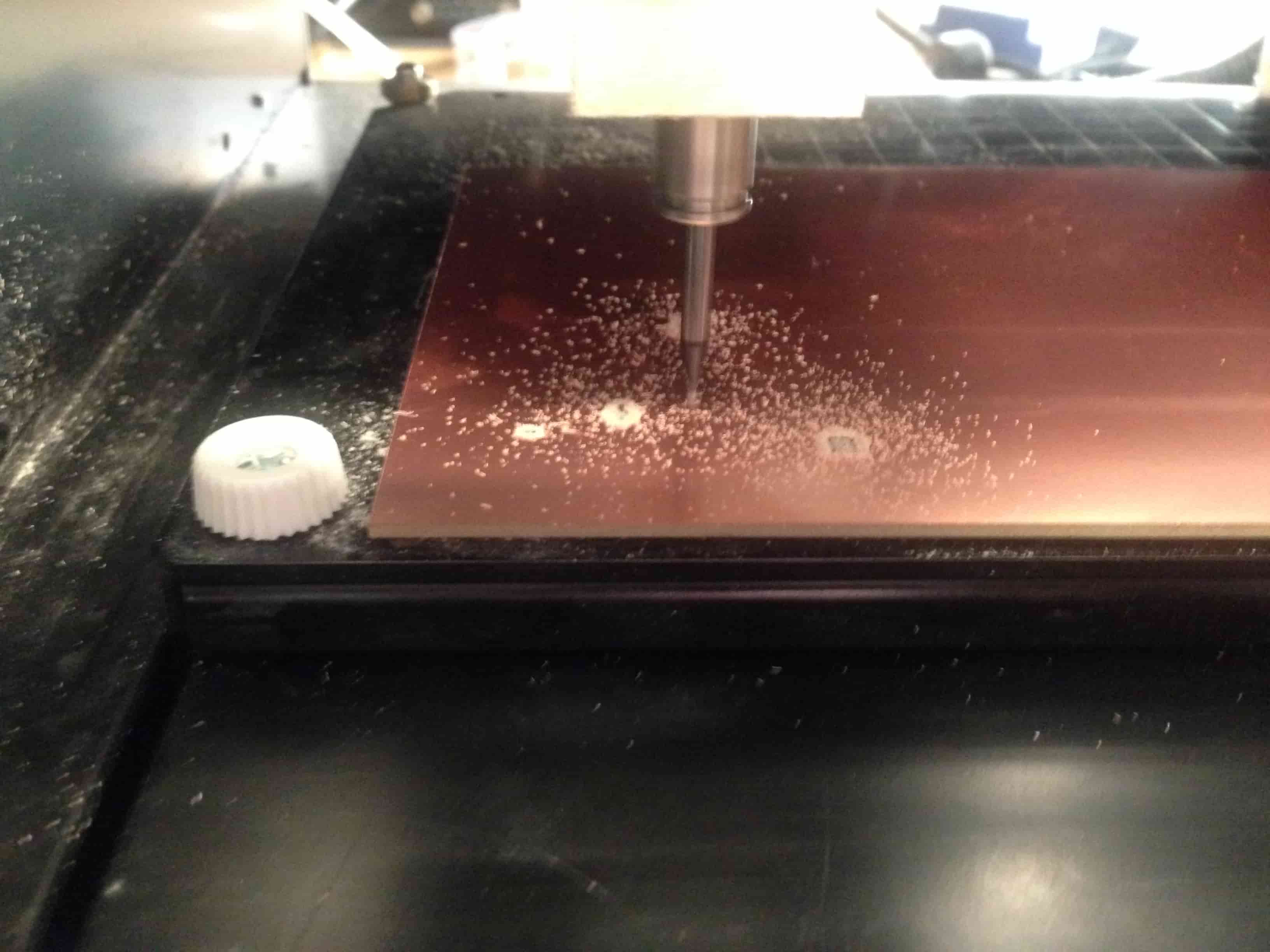
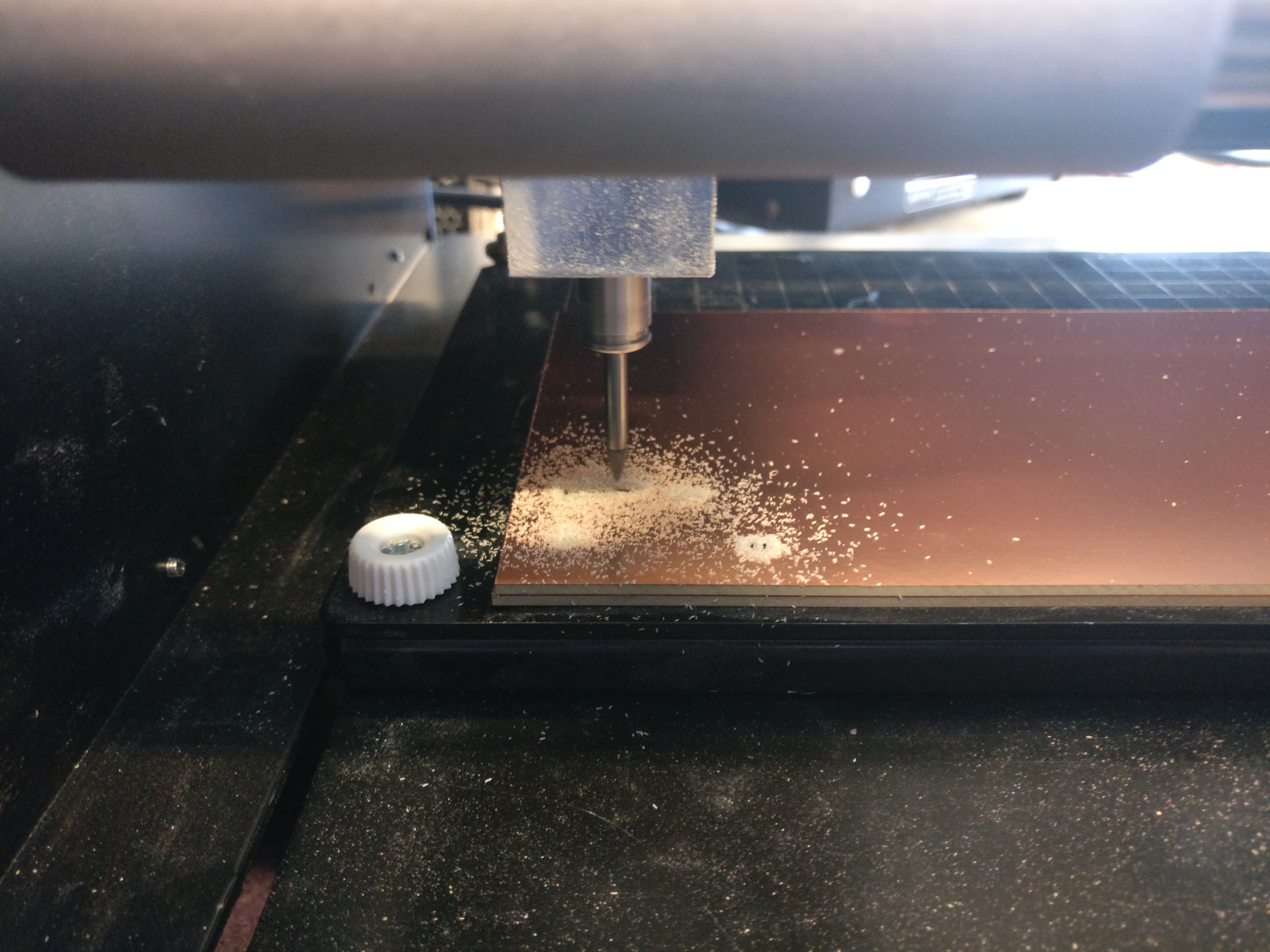
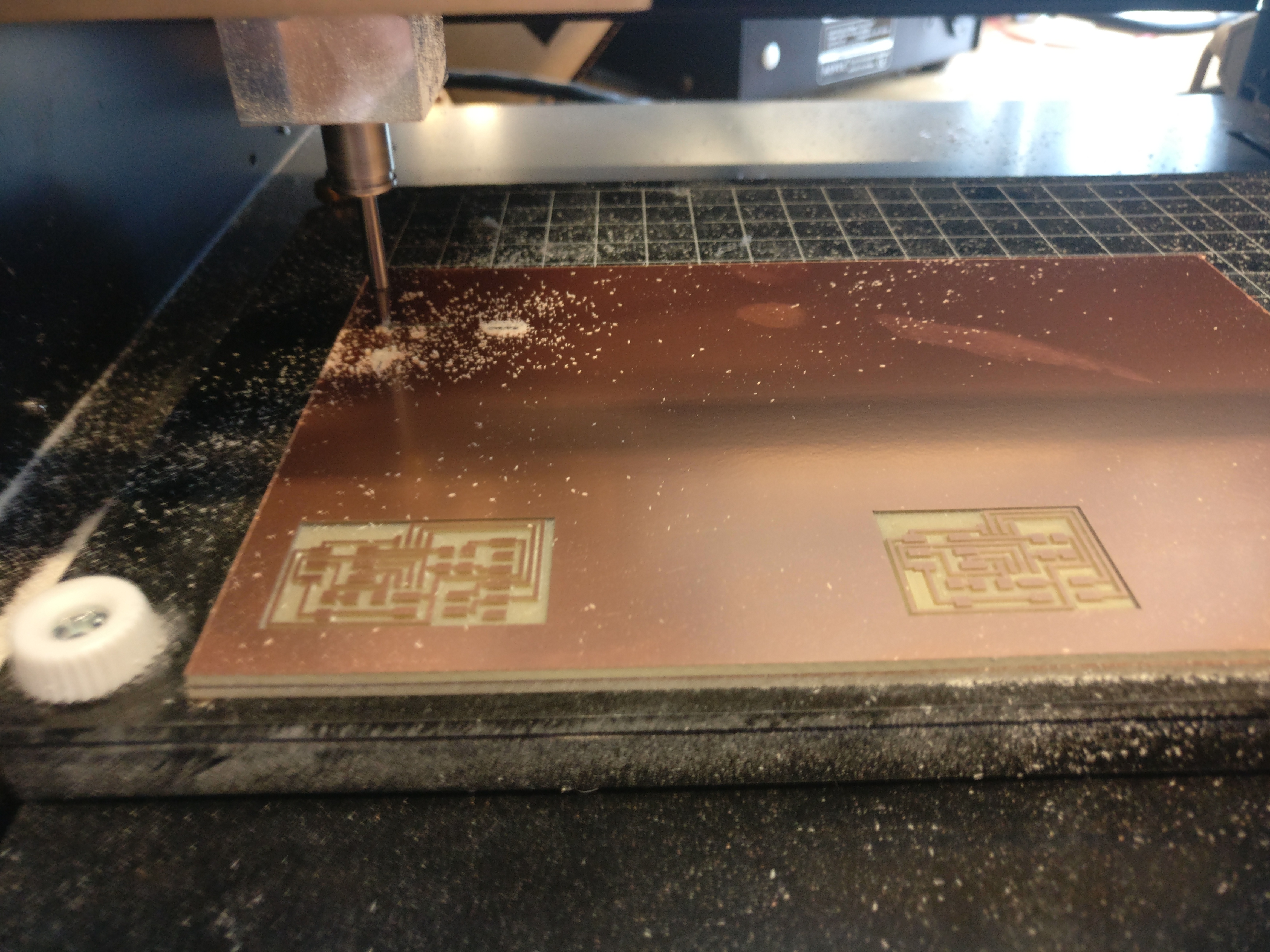
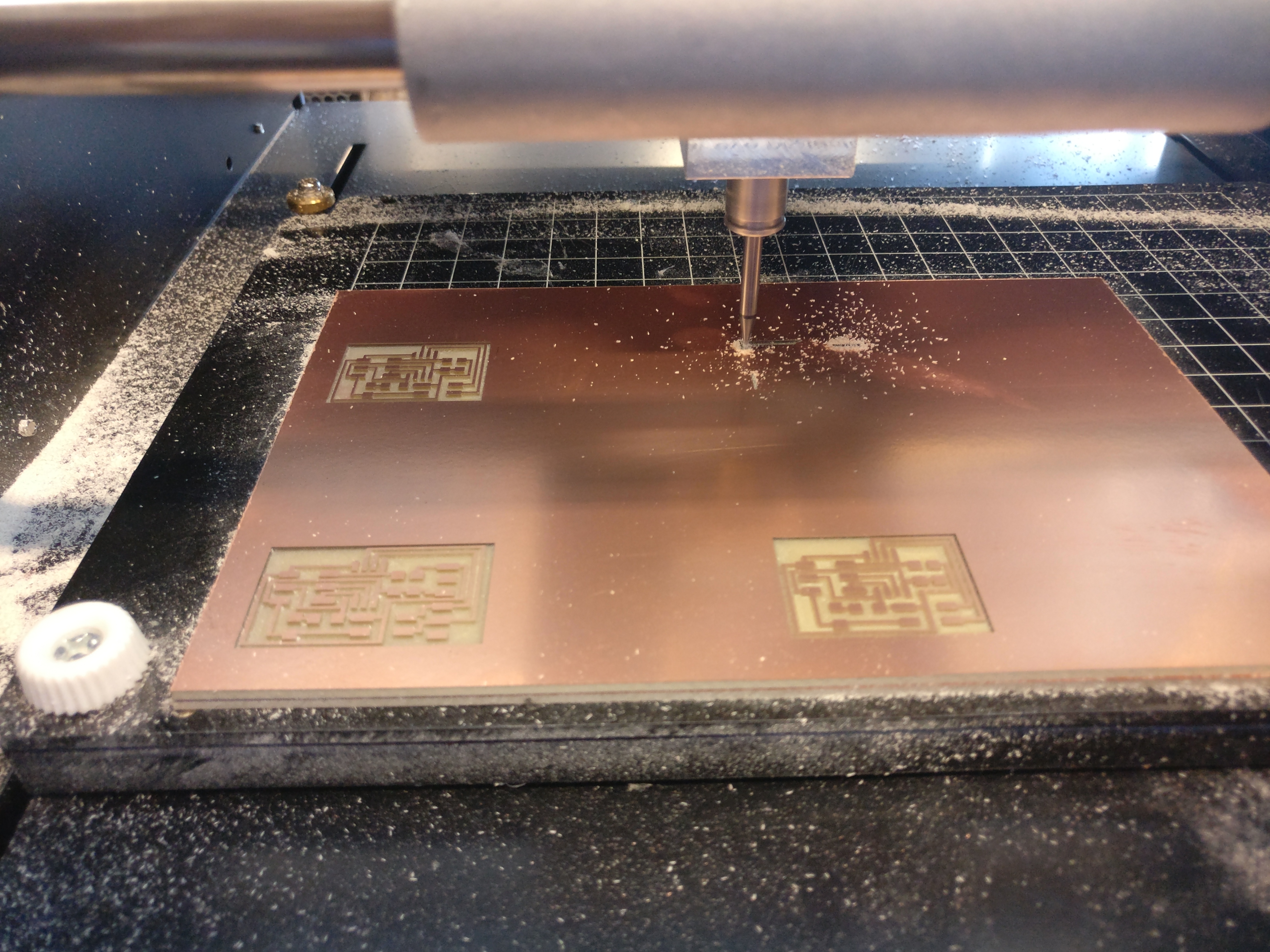
The mini mill is straightfoward. I set the z-axis to the height of my copper board and hit send. I cut the traces with a 1/64 bit and the default Fab module settings and the outline with a 1/32 bit. After the board was complete I noticed one thing. Near the usb port end of the Fab ISP there was excess copper. This I found out after tweeking some settings was an issue with the offset value. I found that for the Fab ISP a number between 4 and 6 works best. |
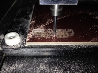
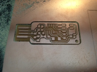
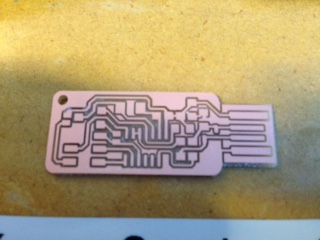
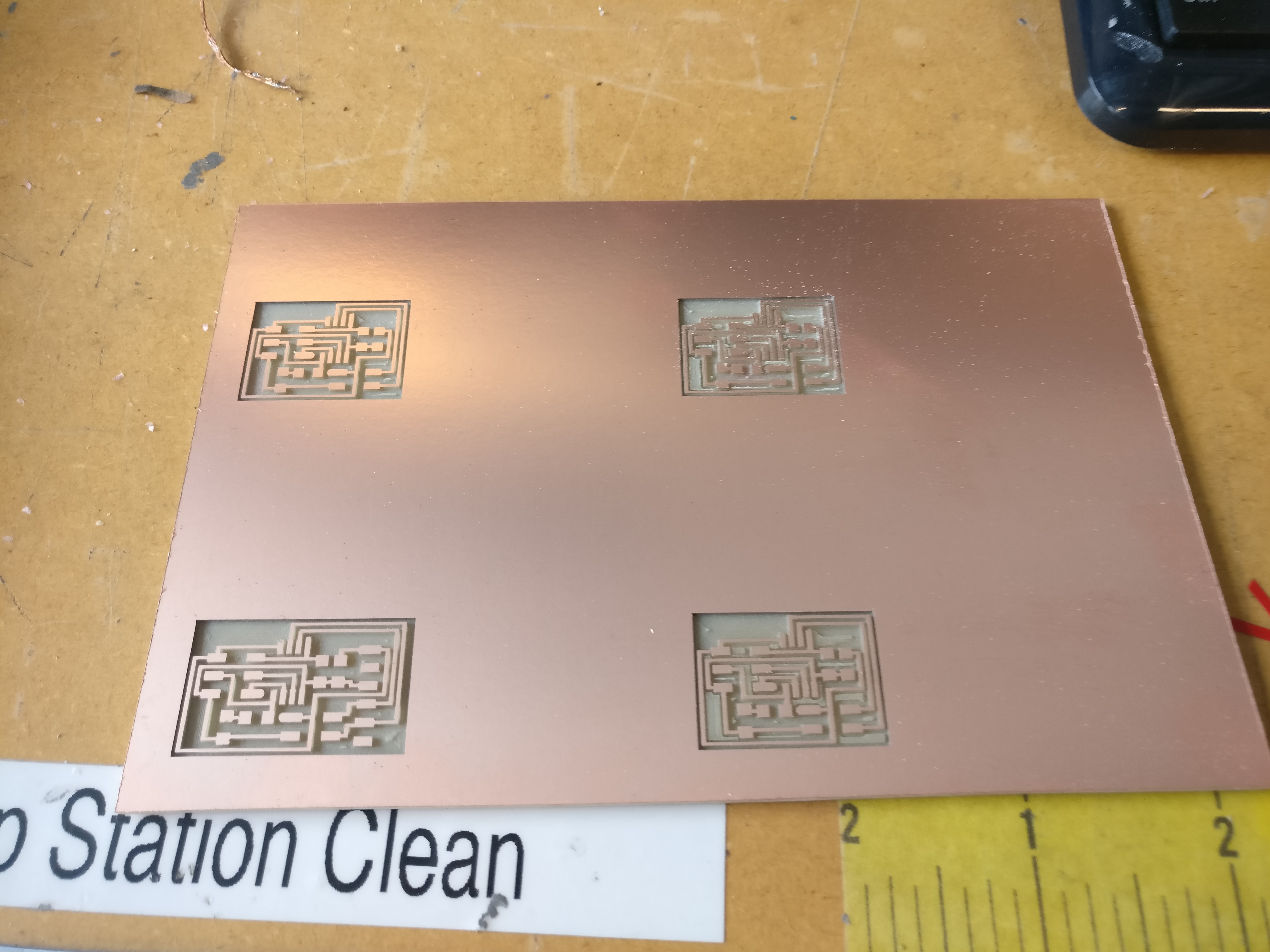
After the settings were adjusted and I cut out the Fab ISP again, it turned out great. |

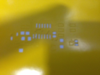
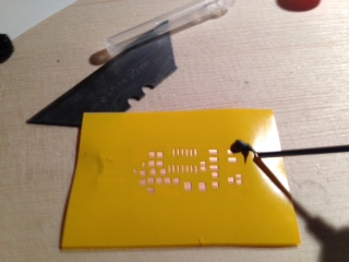
Back to what I was talking about in the beginning of this section, there is one thing that I thought was missing. I decided to make a stencil for the Fab ISP to help apply solder paste. I opened the PNG of the traces in Gimp and removed everything but the pads components will contact.Click here for my solder paste stencil file. |
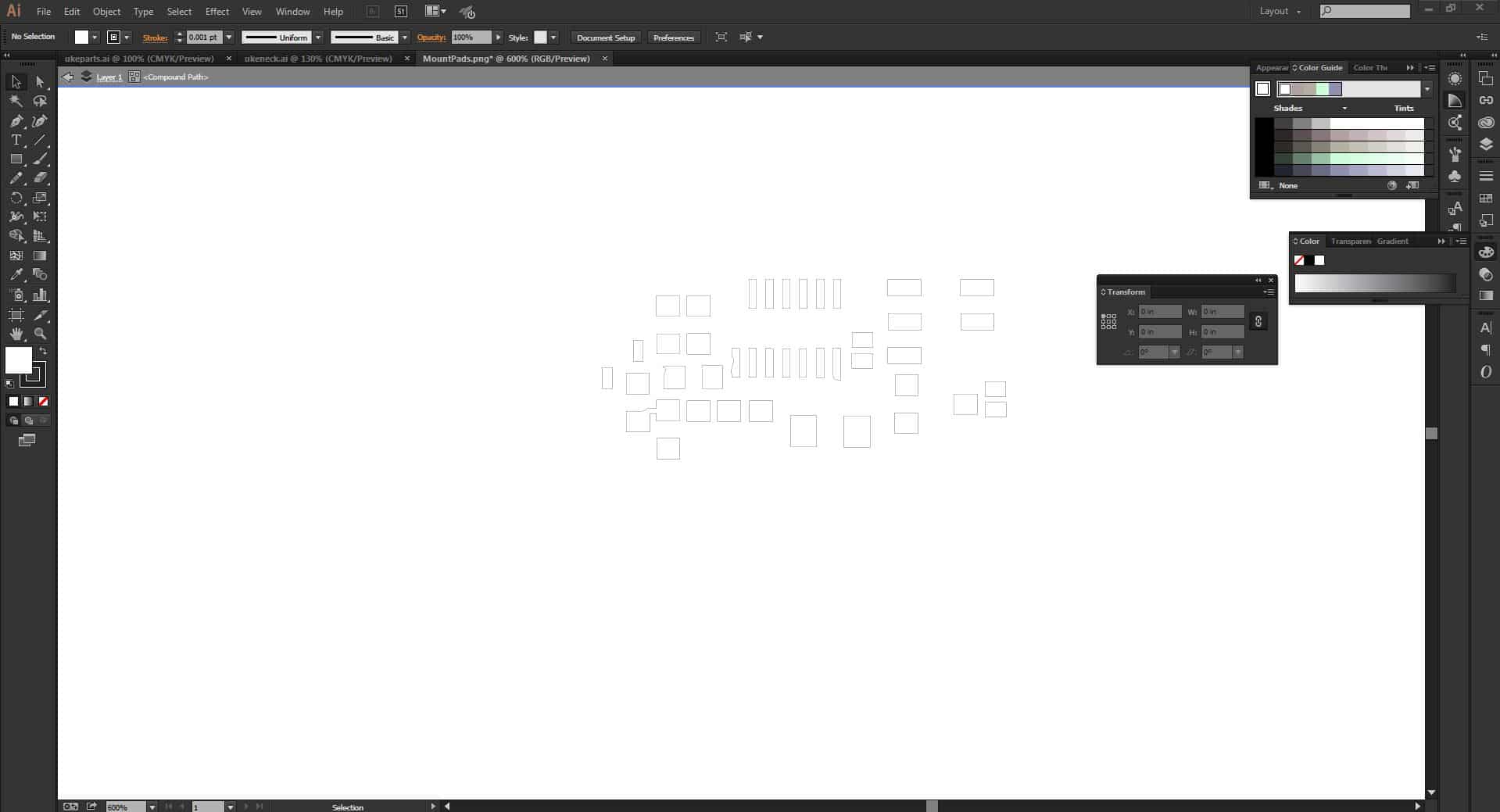
I then opened the file in Adobe Illustrator and traced the image to get a vector outline. From there I made sure to change the stroke to 0.001pt and clicked print to send it to the vinyl cutter. |
The first stencil I cut was alittle to messing. This was because I had the vinyl cutter set to the default cut speed. I found that turning down the vinyl cutter cut speed to the lowest setting in Adobe Illustrator helps give you a clean stencil. |
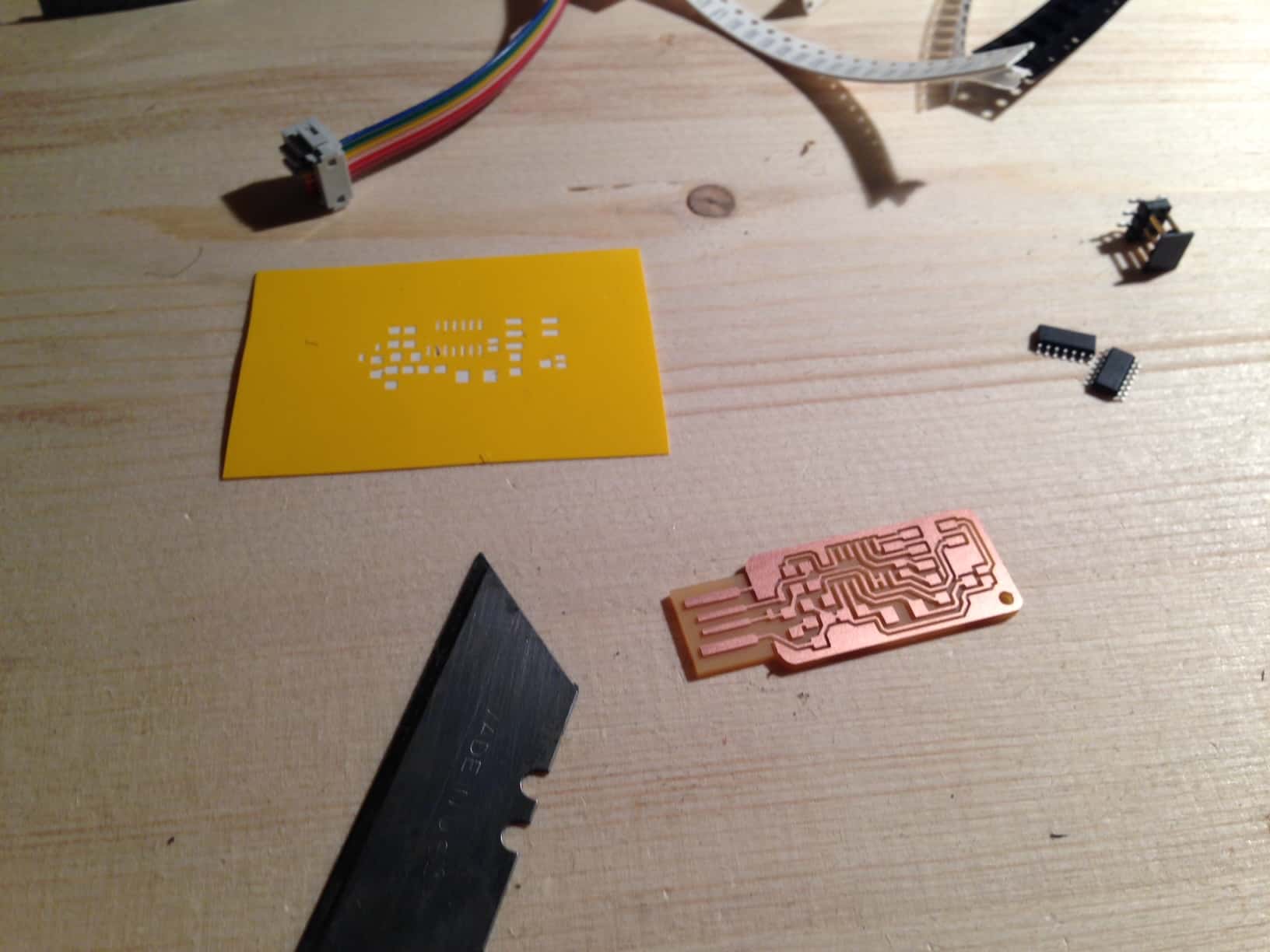
After getting the stencil and board cut out I was ready for assembly. A razor blade is a very handy tool for the next few steps, so make sure to find one. |
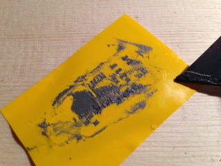
Next I put the vinyl stencil onto the circuit board being careful to line it up as accurately as possible. Then I added a dab of solder paste to the corner of the stencil and spread the paste around with the X-Acto blade. It may not seem like it but a tiny layer, just the thickness of the vinyl, it enough solder to connect your components. Leaving blobs of solder paste will often result in solder bridges and short circuits later in the process. |
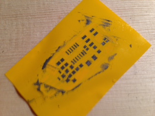
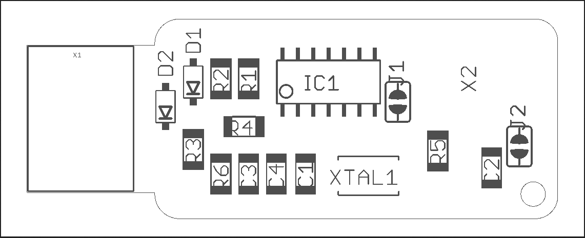
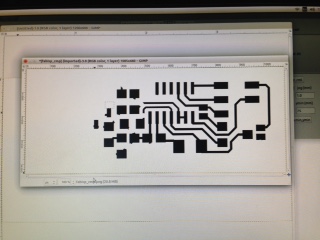
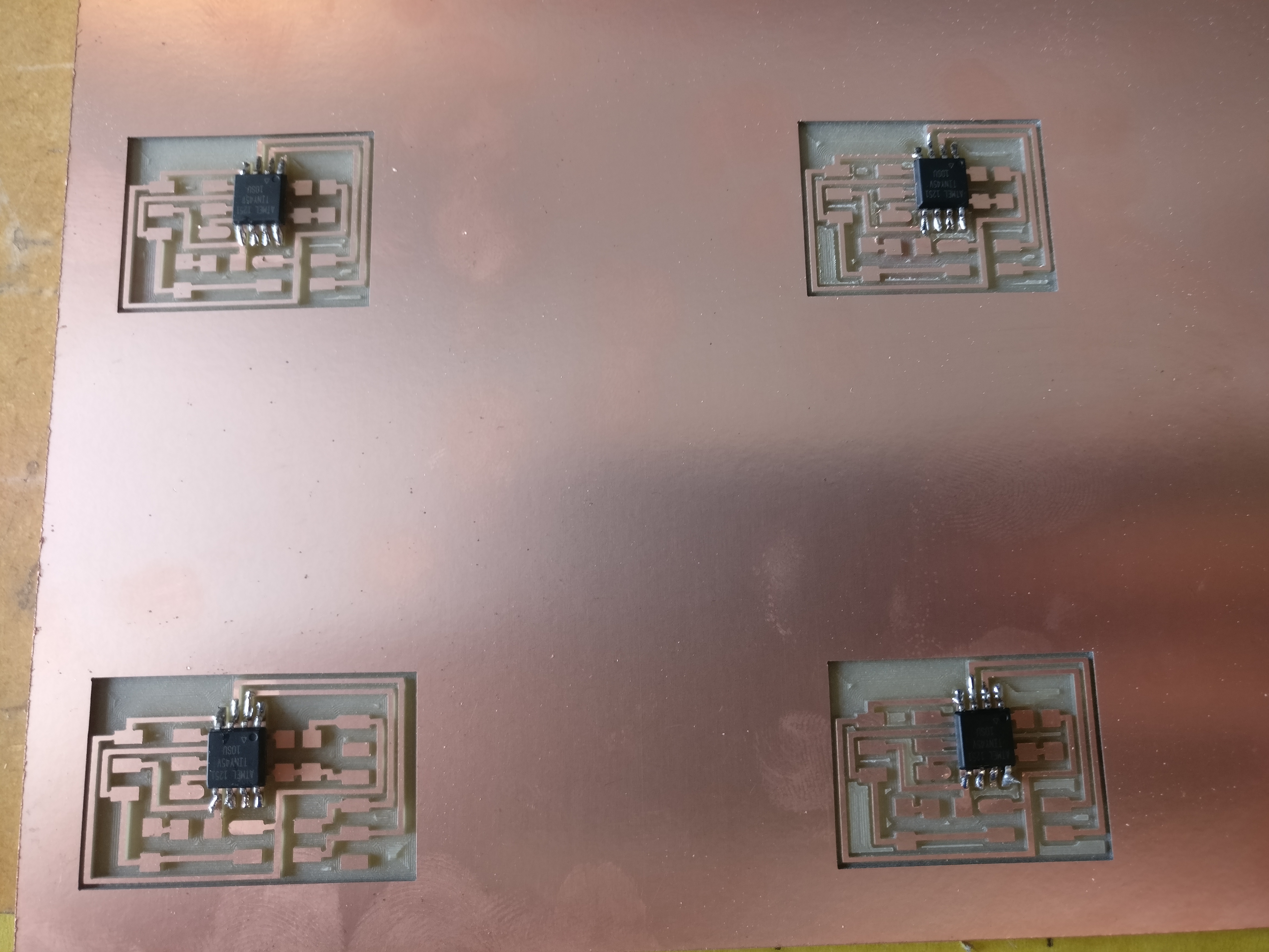
Once I wiped the excess solder paste off of the stencil I peeled it away. Then using ESD steezers(recommended but not totally necessary, regular tweezers work fine) I placed all of the components in their allocated positions on the board. The part numbers on the board layout shown above correspond to this Eagle schematic I downloaded. One thing you will notice when placing your components is that the components that connect to ground(most of the seemingly unused area with no traces in it) do not yet have solder on the side connected to ground because the stencil does not include these locations. Simply place the components and after soldering the sides connecting to the traces, using a re-flow station or soldering iron if you are feeling confindent, place a dab of solder on the ground side and solder the grounds. Just a Note: I would recomend using a hot air reflow station such as the one solder by Sparkfun, I use a temp of ~270 celsius and an airflow of ~2 so that I do not blow the components out of place. |
Don't worry the fun is not over yet. Once all of the components are on and both jumpers are in place(you can make a solder bridge or use a 0 ohm resistor) you are ready to program your new FAB ISP. |
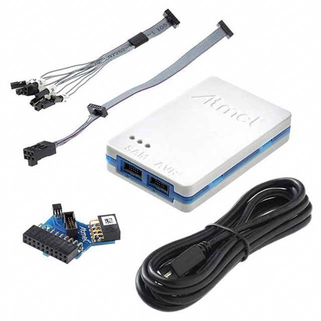
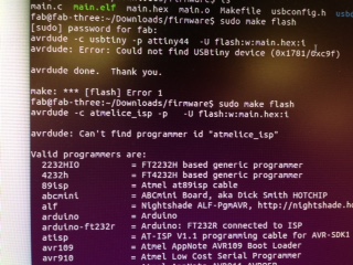
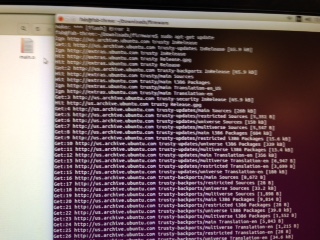
To program my FAB ISP I used Ubuntu, I prefer Linux Mint but Ubuntu works well and that's what we had on the computers in the lab. If you are using a new programmer like the Atmel ICE(which I highly recommend- its available in barebones for $38 or complete kit for $100) avrdude will probably not recognize your device. That meant I had to update AVRDUDE, so in terminal I typed "sudo apt-get update". After the update simply restart your computer to apply the updates and AVRDUDE should recognize the new device, if not simply download the newest version of AVRDUDE using terminal commands. |
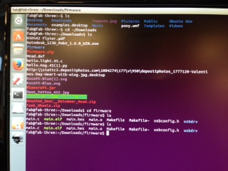
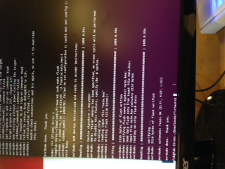
Once AVRDUDE is updated plug your programmer into your computer and connect your FAB ISP to the programmer and a USB port on the computer. Then if you have not already download a Fab ISP make files. This can be done easily with the "wget http://academy.cba.mit.edu/classes/embedded_programming/firmware.zip" command in terminal. Once this is downloaded navigate to the folder in which you just downloaded the files using terminal and unzip the zip file. From there open the make file and change the programmer to your programmer. In my case I was using an Atmel ICE programmer. Note: The Atmel ICE is a programmer and debugger so you must use the name "atmelice_isp" to use it for programming AVR microcontrollers. Finally once you are in the folder containing the make file use these commands. 1. "make clean" 2. "make hex" 3. "sudo make fuse" (if you have not already used a sudo command in your terminal session then it will prompt you for your password if you have one0 4. "sudo make program". If all of the commands work well you are done. I used the command lsusb to check for usb devices afterwords and if everything worked you should be able to see your FAB ISP which will be named something like "Multiple Vendors USBTiny". Finally I unsoldered the solder jumper 1 which is labeled "J1" in the schematic and my ISP was done. |
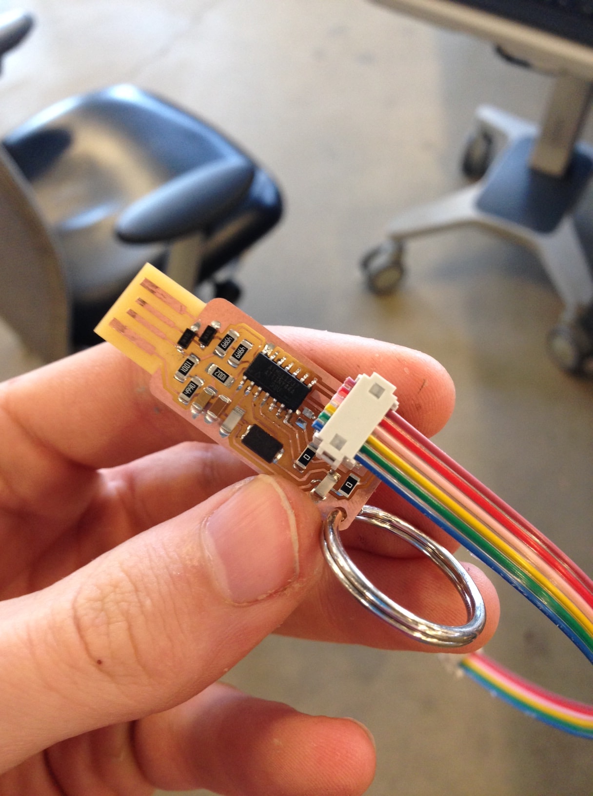
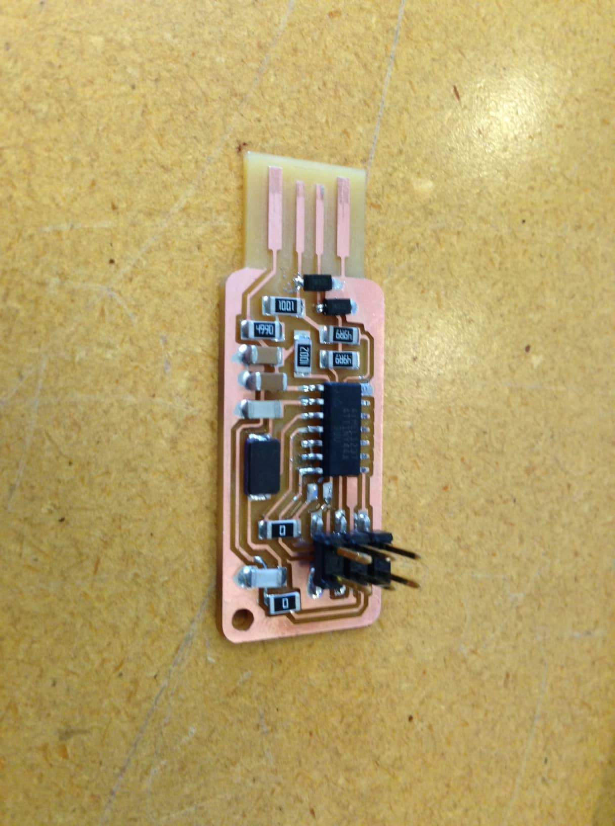
To finish it all of I added a 6 pin ribbon cable I made using a clamp and some cable and plugs to communicate with microprocessors and a key ring to the hole in the side so I could attack it to my wallet or keychain. It is also a good idea to add some tap to the bottom of the USB section and a layer of solder to the top of the USB contacts to ensure good contact with USB ports. |
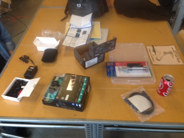
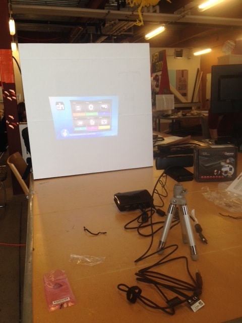
For week 5 I decided that it would be fun to make a structured light scanner for the Fab Lab since we do not currently have one. What we did have was a box labeled "structured light scanner" |
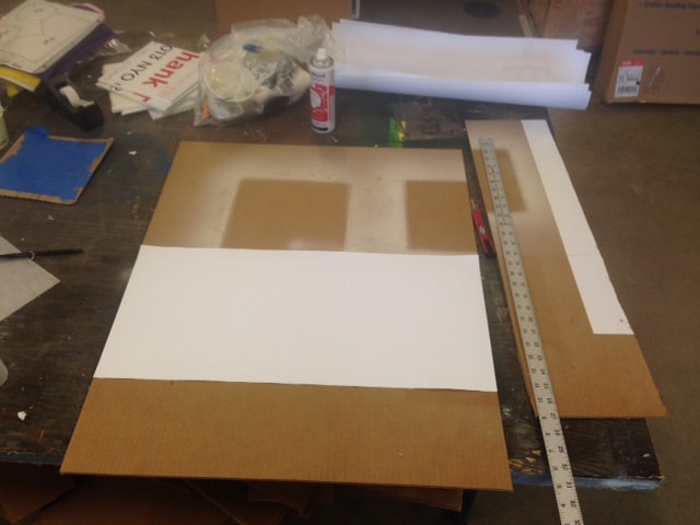
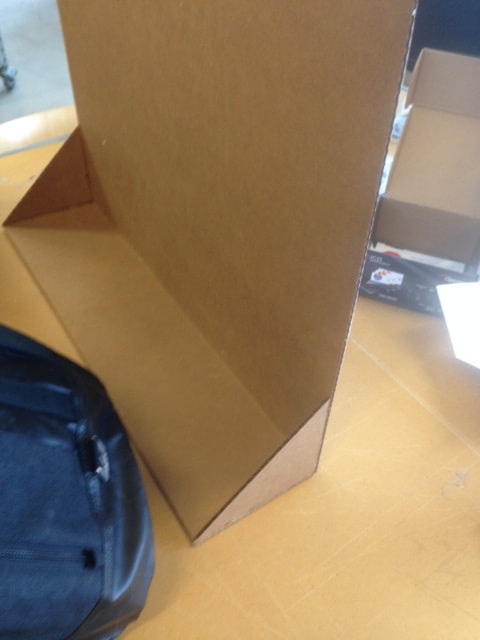
After opening the box I found the following things. A mini Pico Projector, an HD webcam, and a tripod. After opening everything I realized I would need to create a screen of some sort to project on since we do not have a spare here at the Alaska Fab Lab. I used a cardboard square and attached white paper and some supports on the back so it would stand up nicely. |
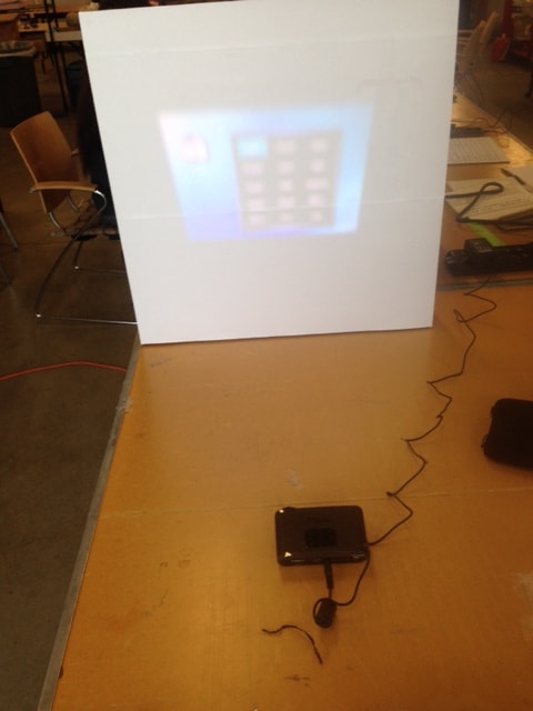
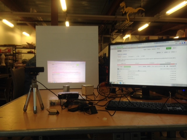
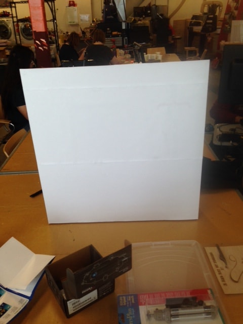
I cleared some space and set up the projector and webcam so that the project was infront of the webcam and projecting onto my newly made screen. Then I set up a computer next to the projector and set up the projector as a second, primary, screen. Note: it has to be the primary screen because when you launch an application and put it into fullscreen mode, which is required in many structured light softwares, it will always display on the primary screen. |
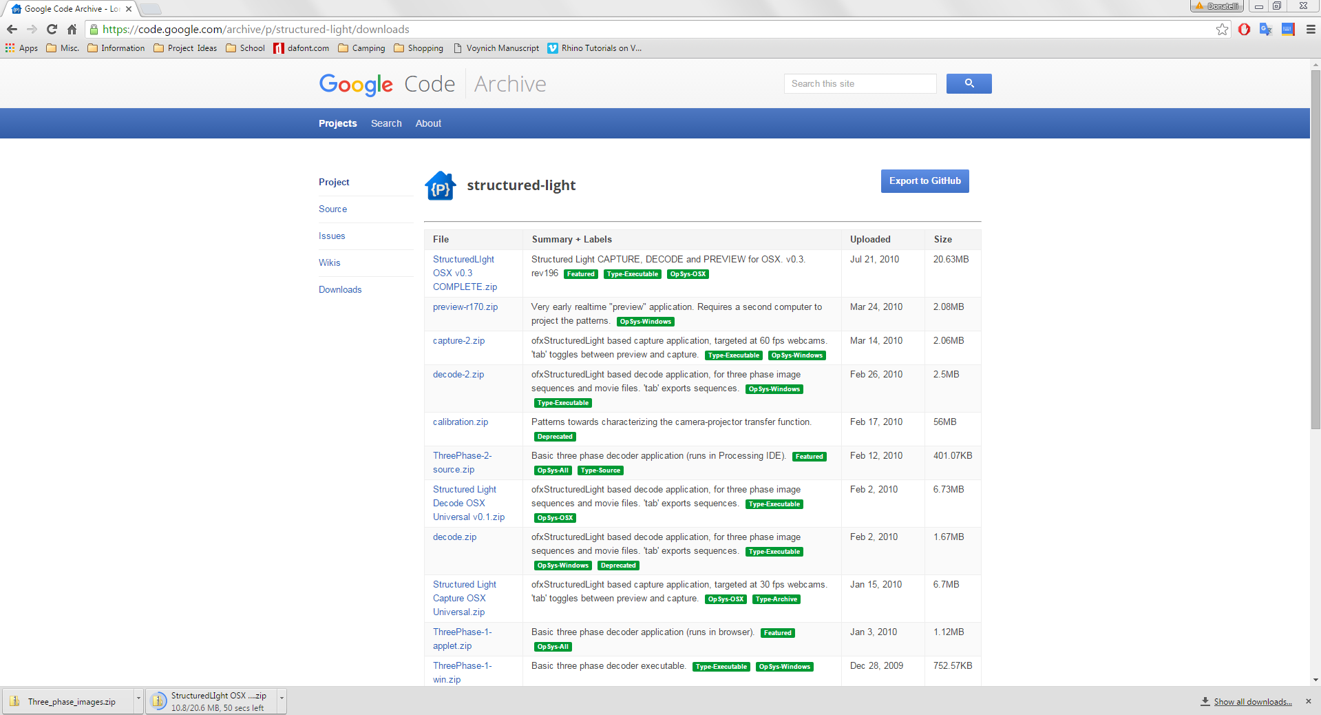
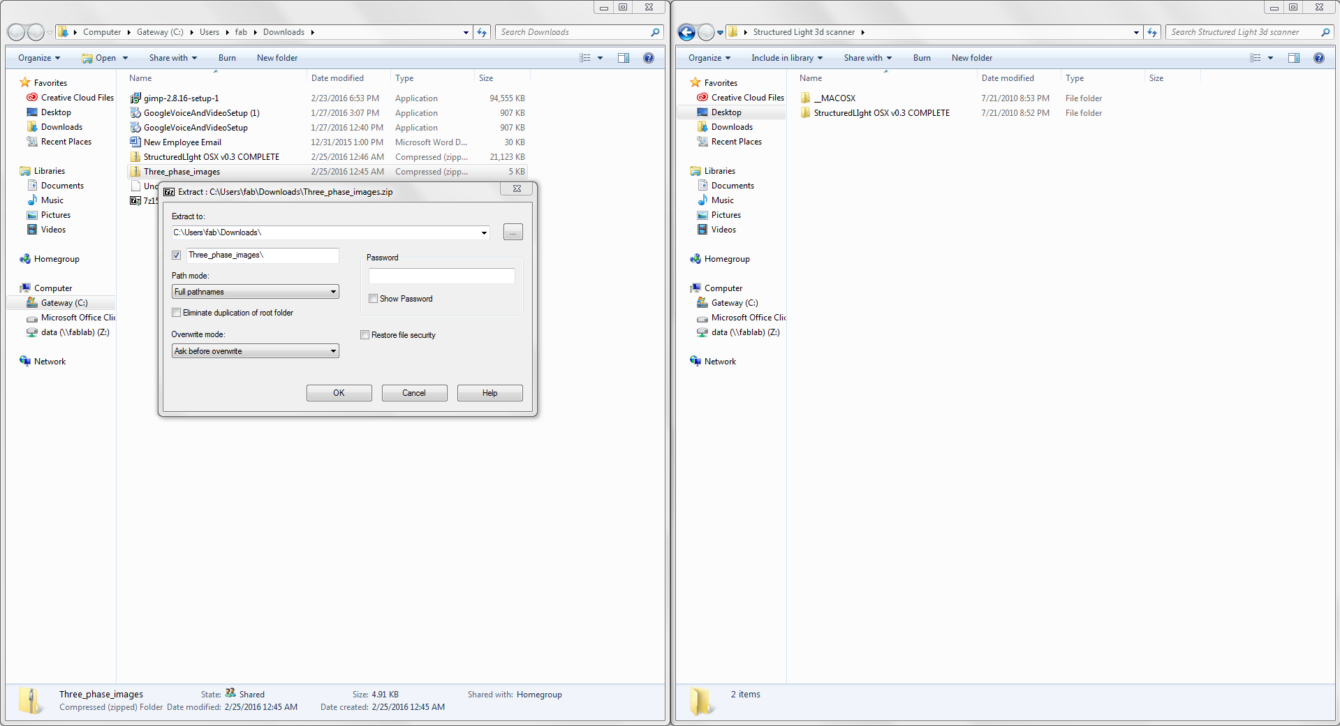
After getting the projector set up I downloaded a structured light software off of Github, unziped the files, and launched the application. |
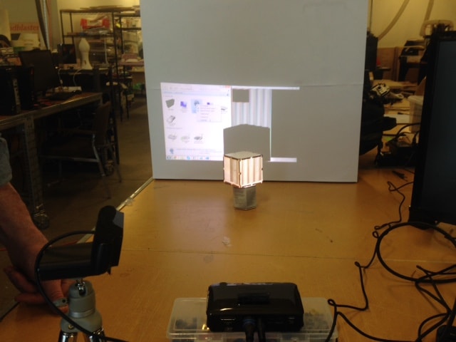
Everything seemed to be working, until I tried to actually take the pictures that would create my 3d model. All of my photos came out as just black images leading me to think that there were no actual pictures being taken. After doing some research I proved myself right, most softwares require a camera linked to the projector via a trigger cable to get precise and accurate photo timing. A web cam only has one usb output and so in most cases it does not work. Since all we have in our Fab Lab are webcams I was not able to actually scan something, but everything is set up for when we get a camera in the future. |
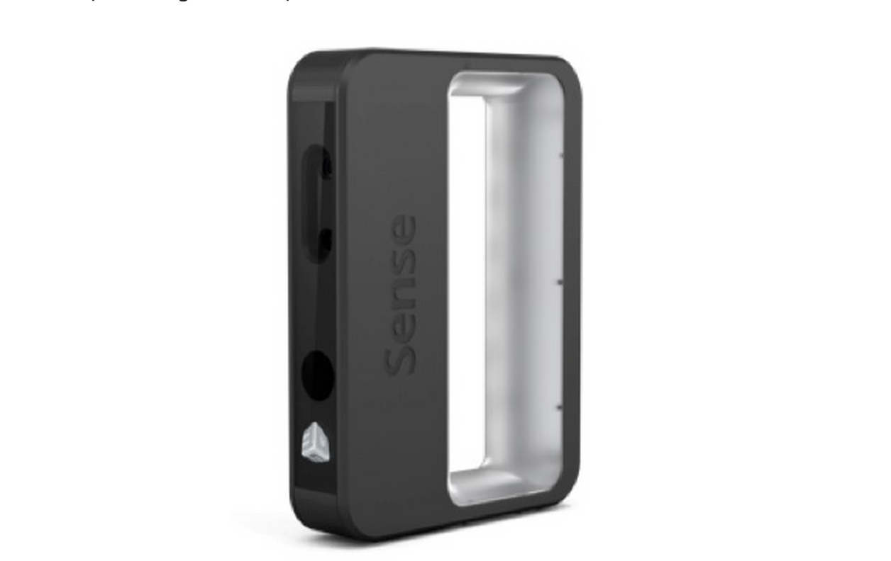
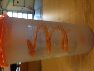
After the structured light scanner I decided to scan myself using a simplified tool, the Sense 3d scanner. The tools has a simple, easy to use interface and produces relatively high quality quick scans. |
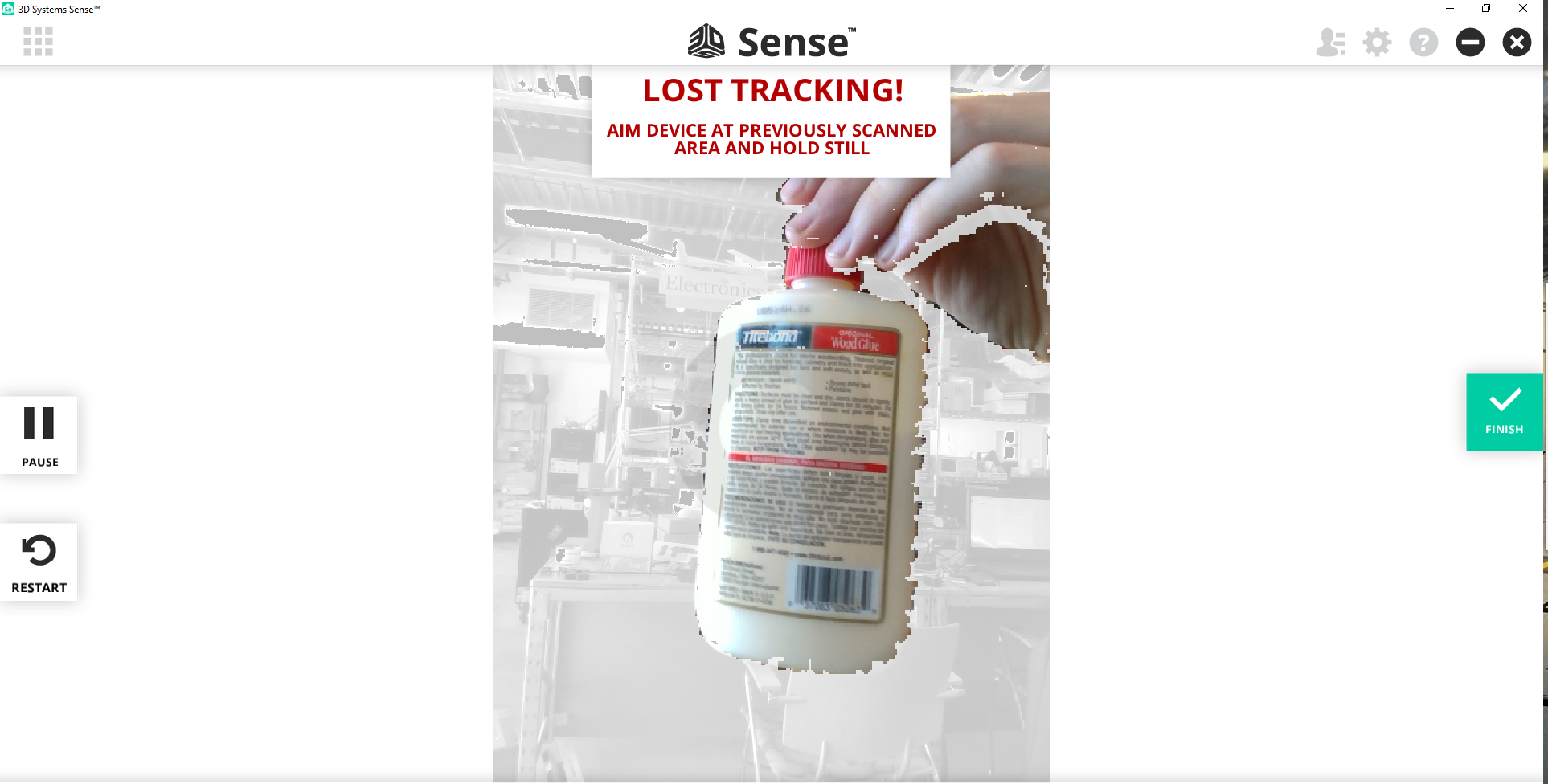
The scanning process is simply. Simply set up the scanner on a tripod or desk and put the object you wish to scan a foot or two away to it becomes highlighted in the scanner window. Then spin the object you are scanning in my case a bottle of glue and then myself 360 degrees slowing. |
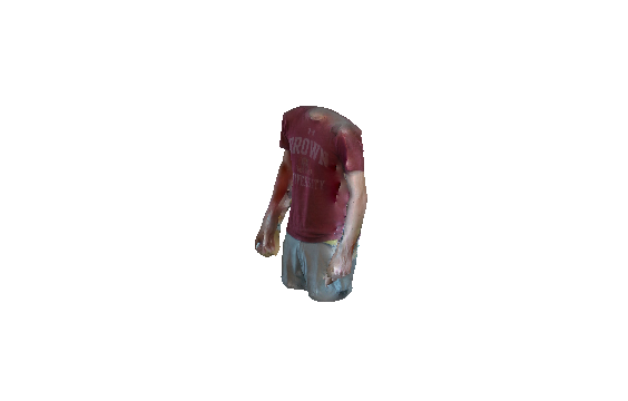
When you click finish the program will automatically generate your 3d scan and you can have the software save the model so you can 3d print your scan. Overall I found the scanner does a good job, allthough the scans are not very accurate. The scanner seems to work best for people, and to do objects with any degree of percision you must have a turntable of some sort to help you smoothly rotate your object. |
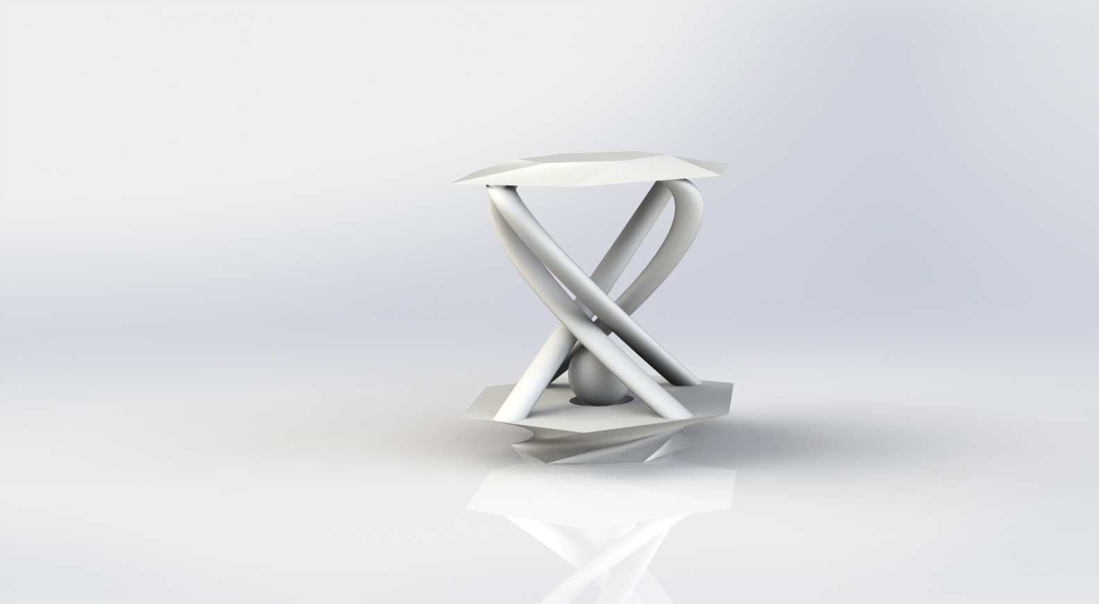
Since I have a pretty good amount of experience with 3D printers and CAD software I decided to make this project tough on the printer. I used Solidworks to quickly design the part above to test the Alaska Fab Lab's Makergear. This object has some pretty steep angles and some a free floating ball in traped in the center so I knew that I would need support material. Click here to download my Solidworks file and try it out on your printer. |
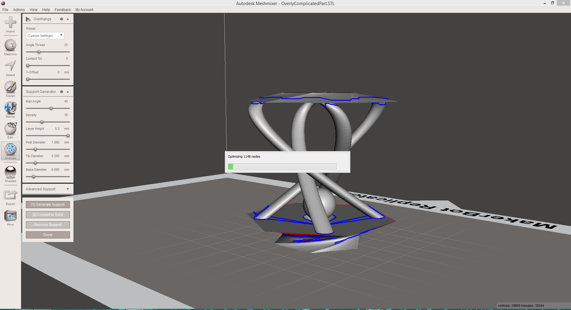
I had heard some good things about Meshmixer and so I decided to download it. It has some structural analysis which is actually pretty good for a free software and will give you a general idea of where you part is weakest. Since I have Solidworks which contains an amazing set of analysis option I was not to excited. What I really wanted to try was the support generation functions. I imported my .stl that I exported from Solidworks and clicked generate support in Meshmixer. Click here to download my model with the support generated in Meshmixer. |
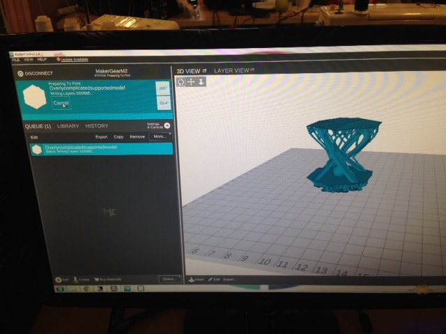
When the support had been generated in Meshmixer I exported the new model as an .stl. I then opened the file in MatterControl, the software we use to run our Makergear, and got the print started. I used the highest accuracty settings in MatterControl and adjusted the external layers to 4, the top and bottom layers to 4, and the infill to 100 percent. When the the print started it missed the first few layers of the support structure, so I stop the print, cleared the print bed, and restarted the print. After two more failed attempts as the support structure on the bottom layer I simply let it continue to print and put down some craft glue to provide a sticky raised area to print and the support structures started taking shape. |
The final result was less than perfect. The print quality was pretty awful even though the printer was set to max quality settings. Ontop of that the model did not finish because the printer stopped half way through the print and never started again. Basically what I learned is that the Makergear might not be up to the task of printing the design I created with the type of support I used. A printer such as a Stratus Systems would be better suited or using more basic grid like support on the Makergear. The support itself that I incorperated using Meshmixer was to complicated for the printer. |
Testing 3d printers can give you alot of insite into the capabilities and appropriate applications of any particular 3d printer. Through the stress testing I found the limitations of single filament 3d printers. I have come to love single filament printers such as the Ultimaker using PLA. This is because of their capabilites and the good smell of PLA:) Though they may seem harder to use at first these high quality yet affordable 3d printers can do alot for you if you know how to use and maintain them. For bigger projects that require ultra high percision or strength it is also good to have access to a printer like a Stratasys Dimension which print with ABS and a support filament. These much more expensive printers can produce parts such as the ones found here in my final project desk. |
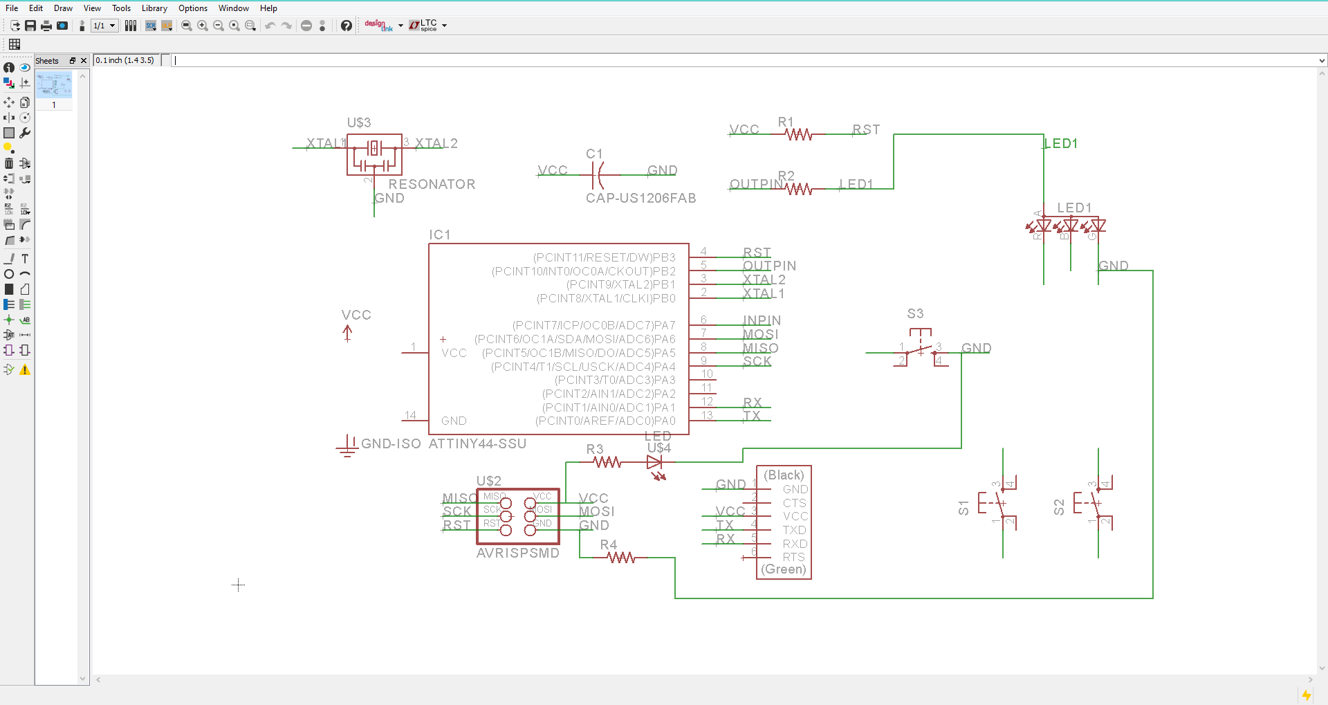
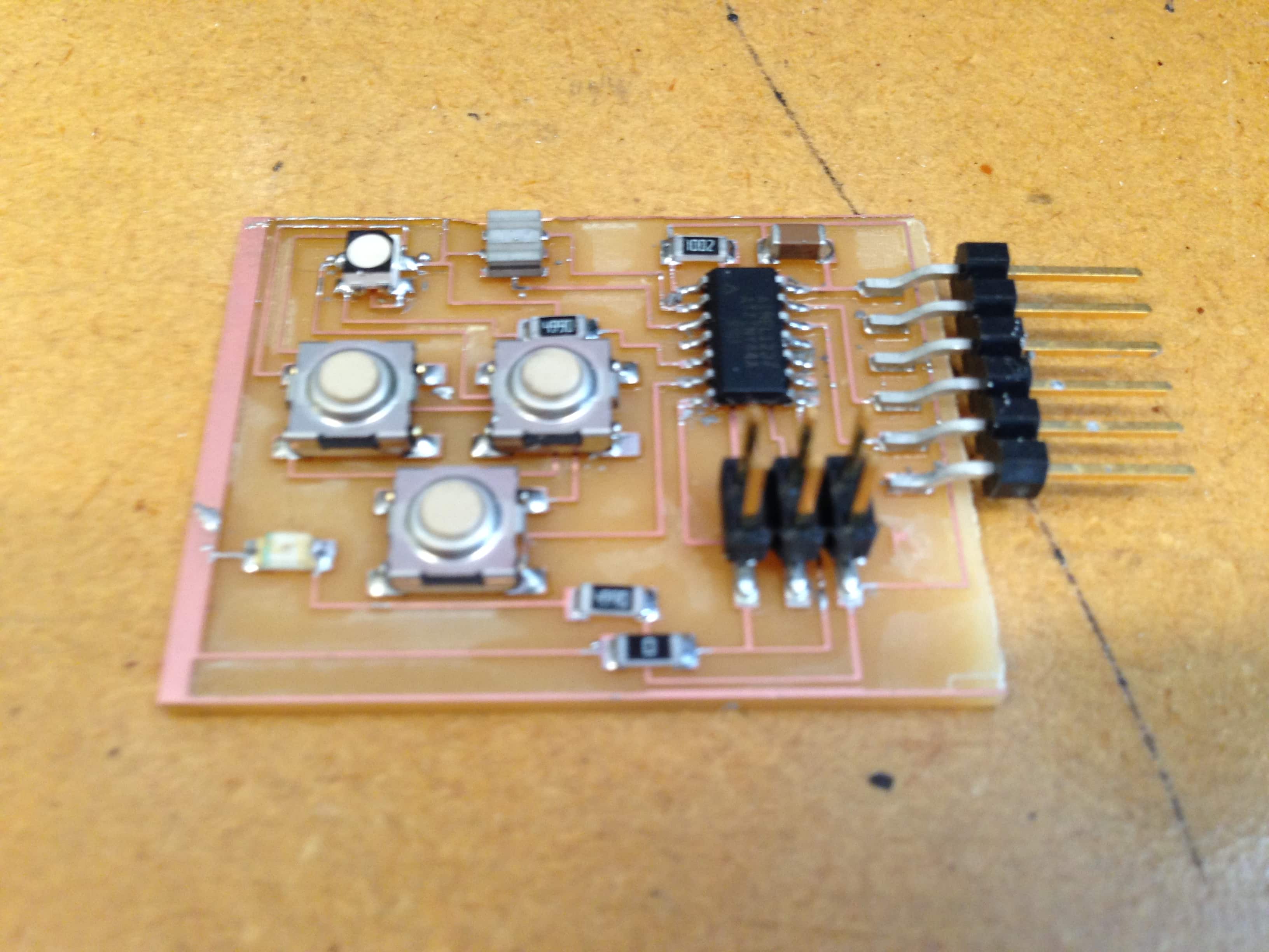
This week I designed a development board of sorts based around the Attiny44. It has 3 buttons an on/off status led and one RGB led. This project was pretty straight forward since I have used Eagle before. In Eagle you incorperate electronic componenets into your schematic through libraries of componenets. Many places like Adafruit and Sparkfun have component libraries available for download. I already had the Fab Lab component library downloaded so I got to skip that step. Then using the add component tool I placed my components and linked the connections between then using the naming tool instead of drawing wires between them all. This makes your schematic look much cleaner. All in all Eagle is a great software for circuit and circuit board design but sometimes finding the part you are looking for can be a huge pain. |
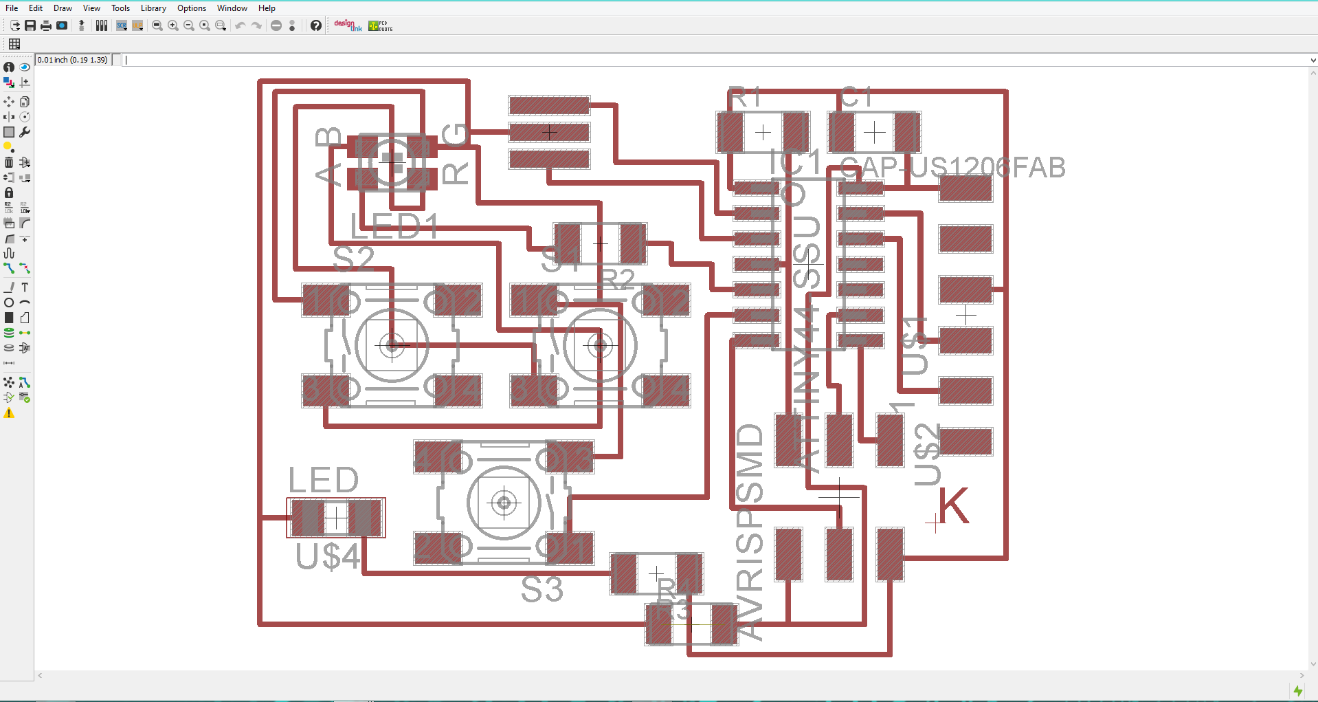
Once I designed my circuit I went on to design the board layout for my circuit. In Eagle this is a pretty straight forward process, but when making a single layer board it can be tricky to make all of your traces neat. Using 0 ohm resistors as jumpers to jump over other traces is a life saving trick. In Eagle all of your components will show up in board view and little yellow lines will connect the components together. Using the traces tool you can draw the connections in the way you would like until you cannot see anymore yellow lines. At this point as long as your circuit is correct you are done designing your circuit board in Eagle. One note, my line thickness was set at 0.016. This turned out to be rather thin and though it did work the traces are fragile. |
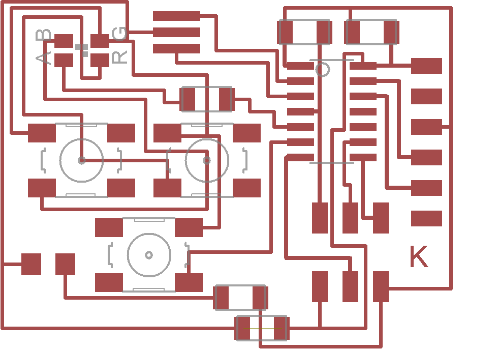
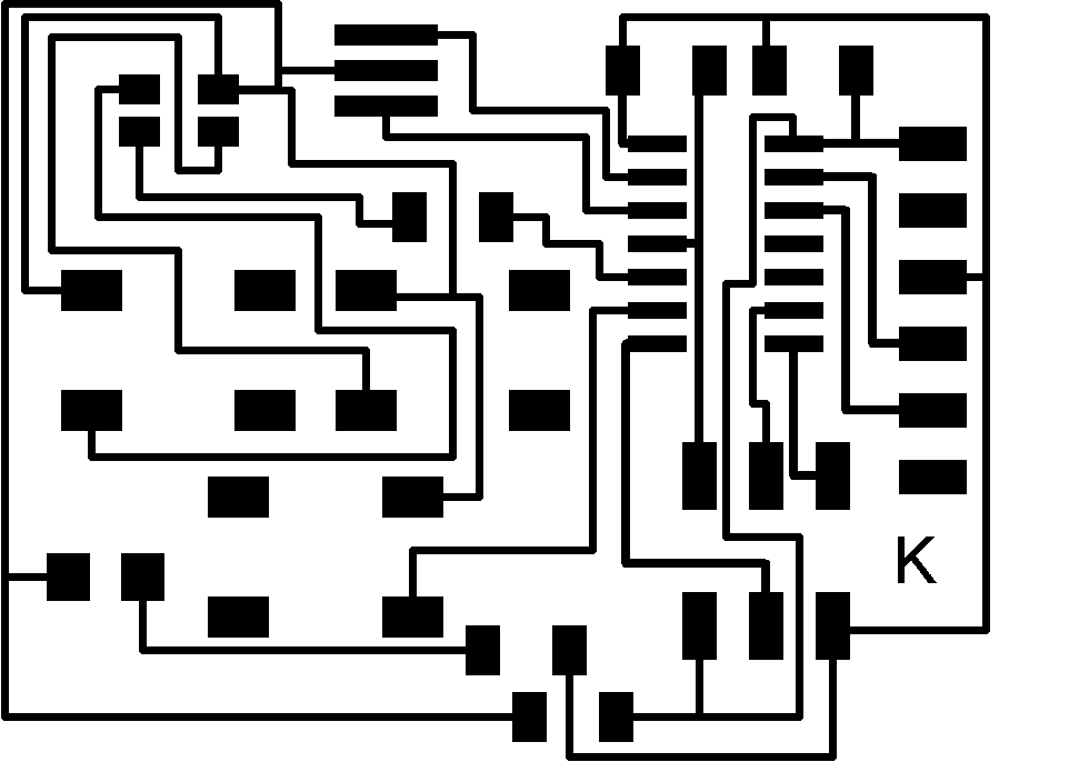
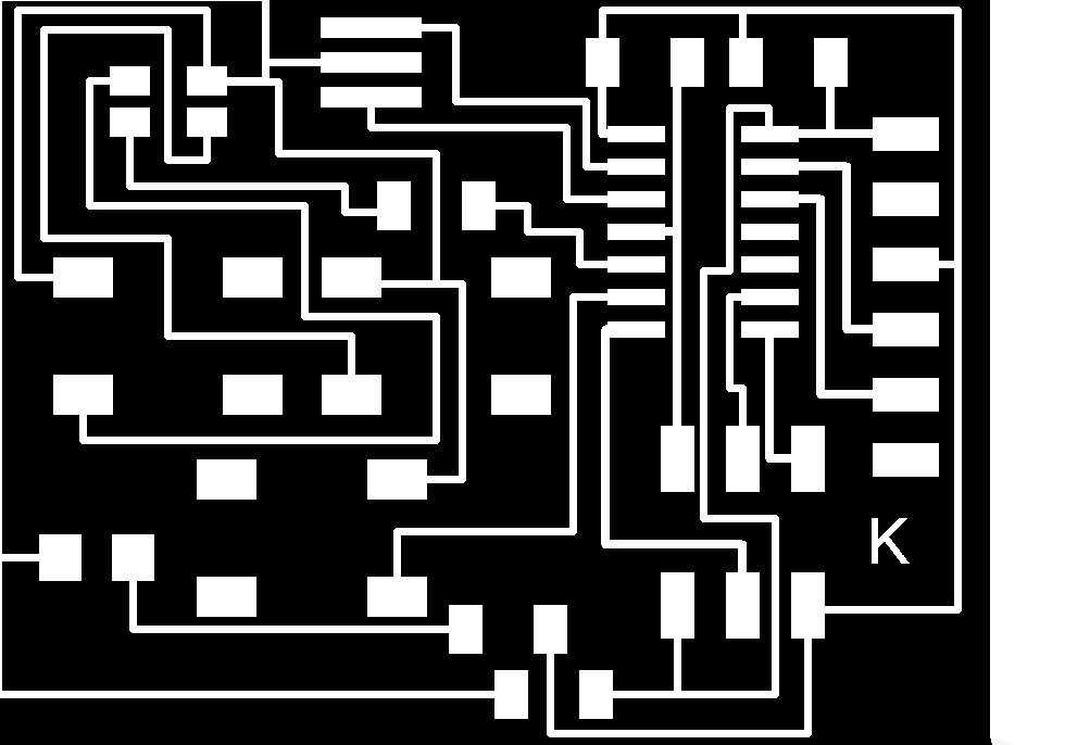
Once my board was done all I needed to do was disable all of the layers except for my traces. This can be done by going to the layers menu in Eagle. I think exported the traces in monochrome. I opened the saved file in Gimp and inverted the colors so the traces and pads were white and the area I wanted to remove was black. |

The next step was simple but very important. I duplicated the file containing the traces, opened it in Adobe Illustrator and drew a rectangle around it. Then I deleted the traces so all that was left was the outline of my board, remember to make sure that the line thickness is at least 1/32 so the mini mill will cut it. |
After all my design work was finished I opened the traces in the Fab Module and set the settings to default except for the fill which I set to -6. Then I hit "send it" and the cut started. See my earlier Fab ISP for a more detailed explanation of using the Modela Mini Mill to cut circuit boards. |

The board took about 15 minutes to mill out. Then I switched to a 1/32 bit and loaded my outline file, again using the defaults for the 1/32 bit. |
Once the board was completely milled out I used tweezers to apply solder paste to the pads where components would be placed. Then I placed the SMT components and used a hot air reflow gun set to 270 degrees to melt and solidify the solder paste. Make sure when using a reflow gun with surface mount components to keep the airflow very low so you do not blow your components out of allignment. |

But when your done don't forget the Fablab tradition of Fabbercise. I decided to take it to the next level with some outdoor moutain biking adventures here in Anchorage, Alaska for my weekly dose of fabbercise. |
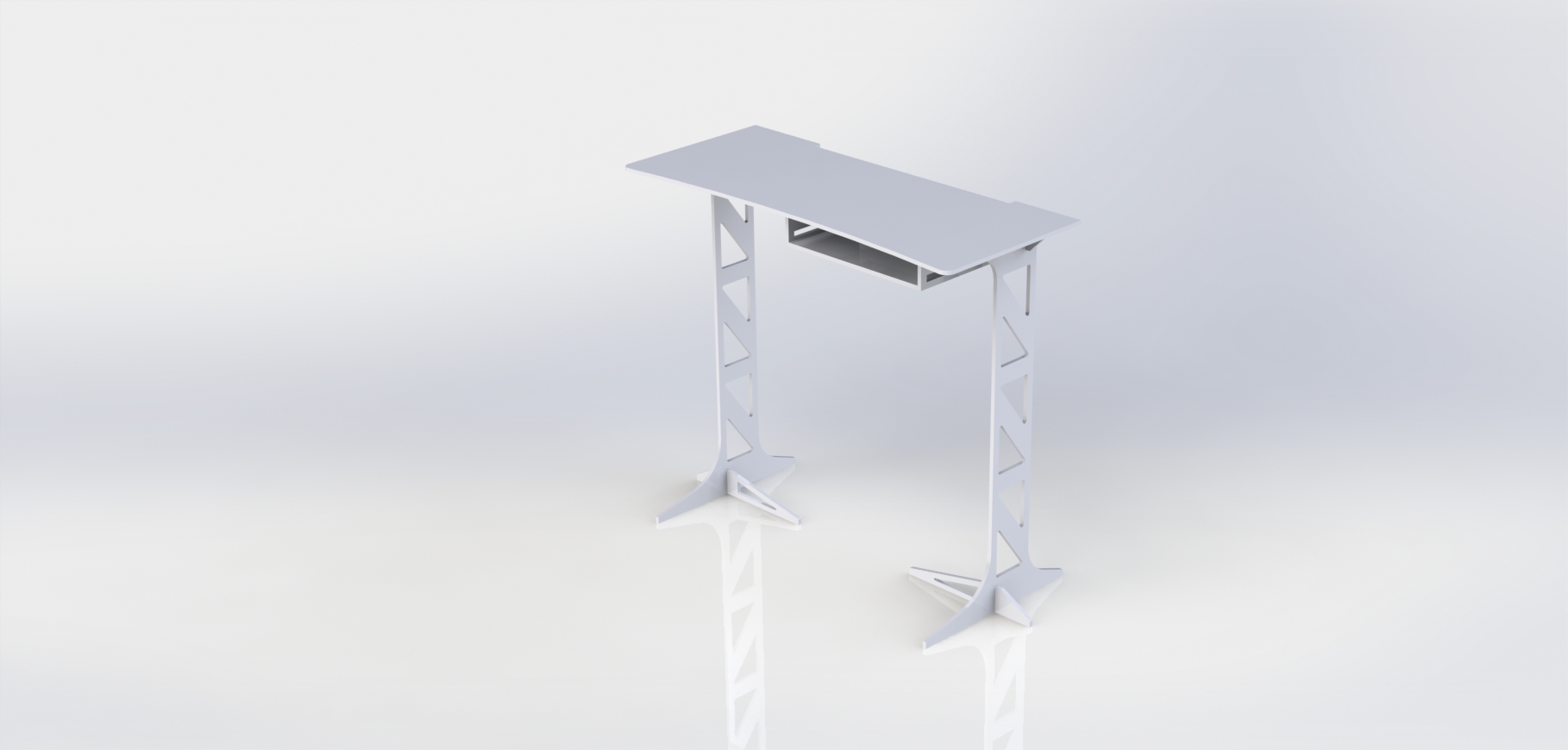
For this week I choose to make a quick and simple standup desk. I wanted to be able to work standing up infront of the living room window in my house. All I had on hand was one piece of 1/2" plywood so I jumped into Solidworks and started designing my new desk. One note. The render above from Solidworks has one component that I didn't end up attaching to the physical desk, it is the draw like piece below the desk surface. This is for a laptop or desktop computer if someone wants to use an external monitor and keyboard ontop of the desk and have the actual computer under the desk surface. |
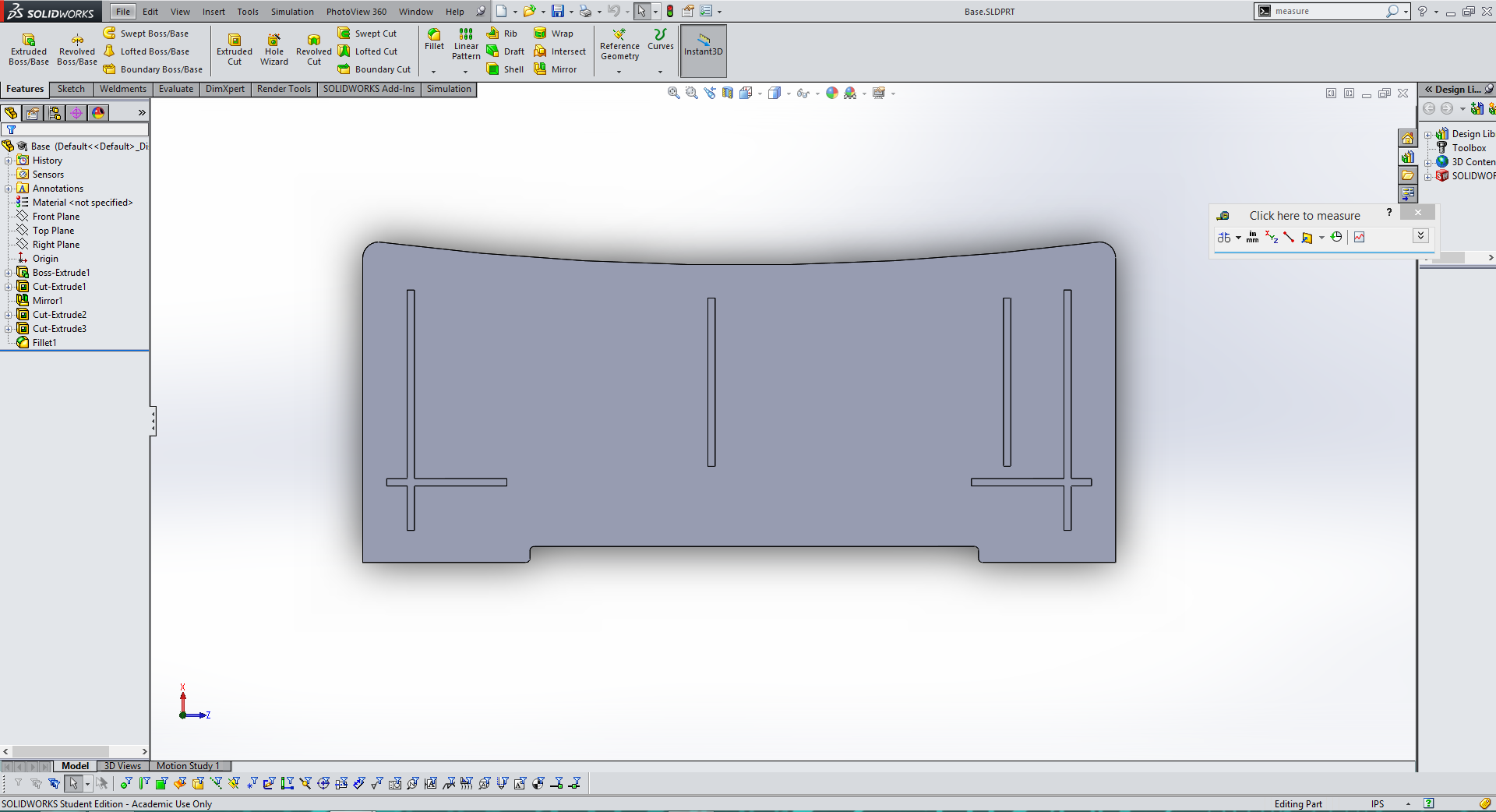
I started by designing the top surface of the desk. Since I was going to cut the desk with a 3 axis CNC machine I only made cuts from one side of the desk top, the bottom. I put in notches for the legs and supports as well as a cut out in the back for cables to run down the bottom of my desk without being squished between the wall and the desk. Finally for a finishing touch I added a slight indent to the front of the desk. |
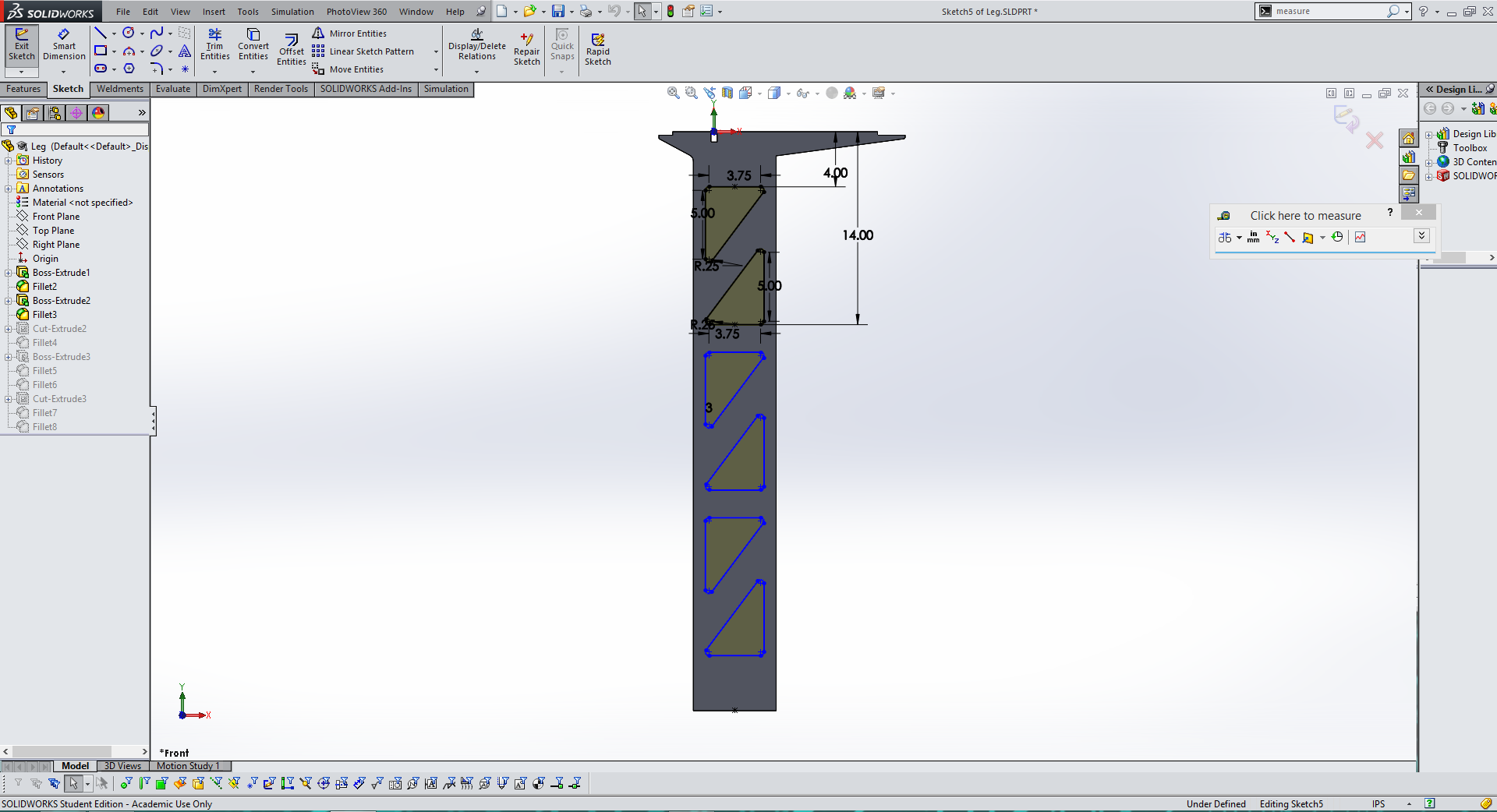
The next step was designing the leg of the desk. Again, I desking it all from one side so it could be cut out on the 3 axis ShopBot. I added an extruded section at the top to fit into the notch and cut out holes in the side of the legs to make the design more sleek. Finally I cut notches in the top and bottom for the additional supports that will run perpindicular to the legs. |
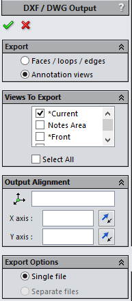
After I designed all of my parts I exported them as line images from Solidworks by going to "Save As" and then selecting .dxf. Then I used Solidwork's export tool to select the view I wanted as seen above. |
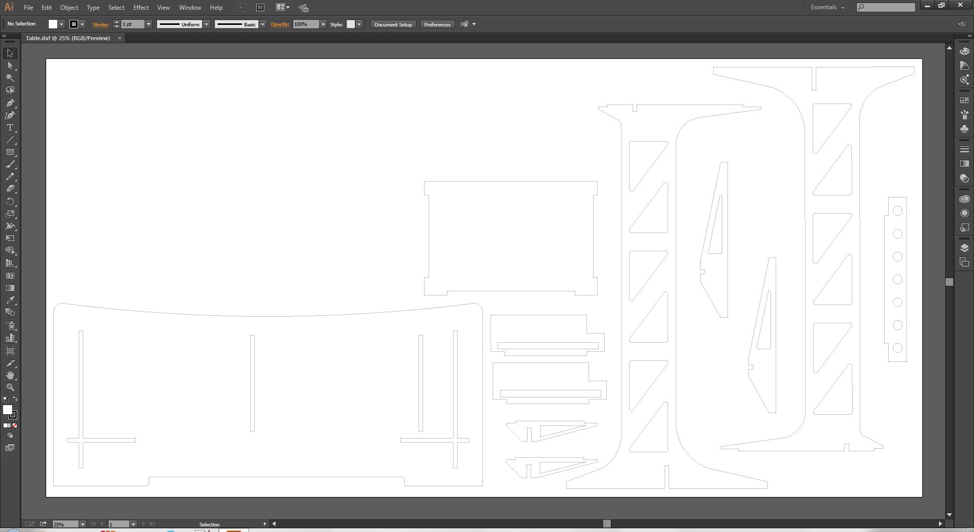
Next I create a 4' by 8' artboard in Adobe Illustrator to arrange my parts for cutting on the ShopBot. I made sure to space the parts far enough apart to that the 1/4" cutting bit had room to cut between parts. Finally I exported the new layout as a .dxf so that I could design the toolpaths in Aspire. |
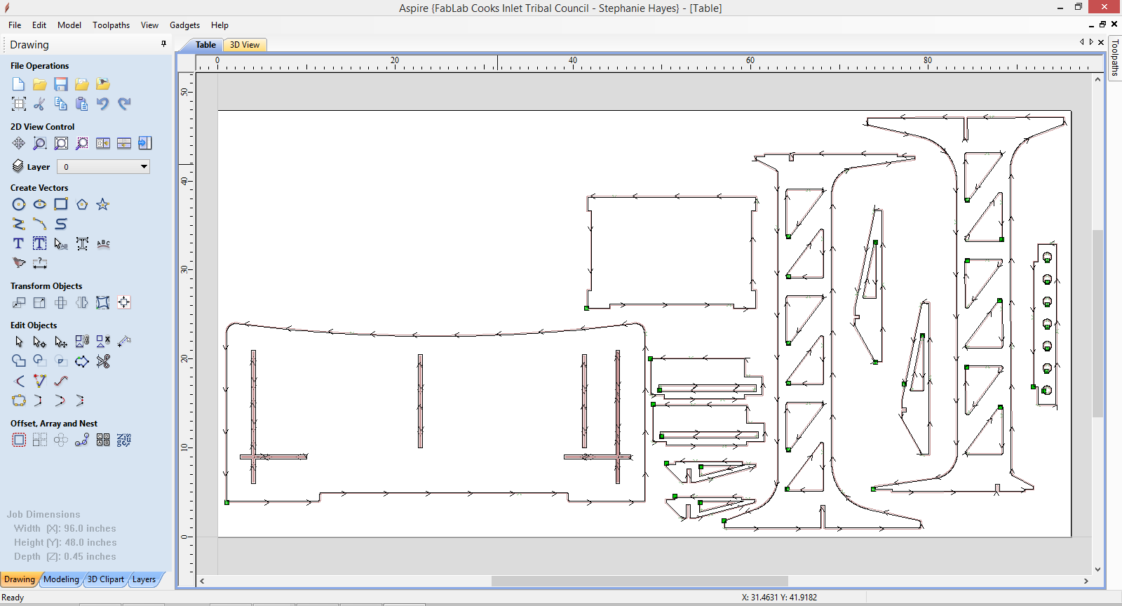
I opened the .dxf file in Aspire and used its toolpath tools to create my three toolpaths. One for the pockets that had to be milled 1/4" into the material. Another for the interal cuts and a final one for the exterior cuts. I used Aspire's tools for creating tabs to hold the cut parts onto the sheet of cardboard during the cut process. Tabs are often better than screws because you do not have to guess where to place the screws before you start cutting and tabs eliminate unnecessary holes in the plywood. |
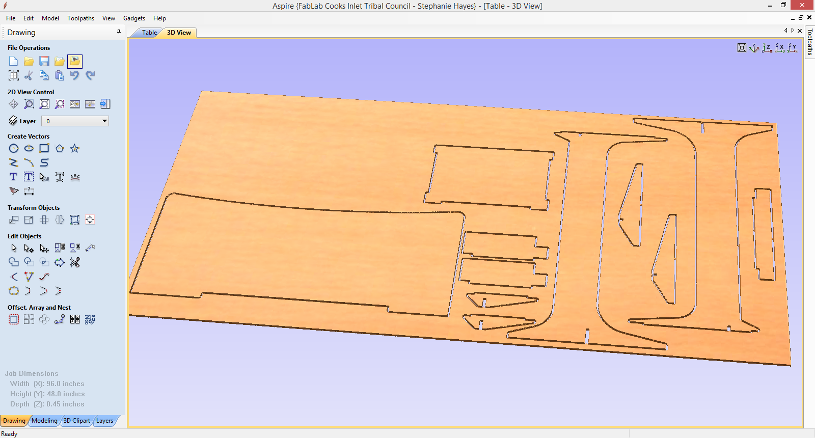
Aspire also has a convenient tool for previewing your toolspaths so that you can make sure they are all correct before you cut. As you can see above the cutouts in the leg sections of the desk are not included in a toolpath yet. |
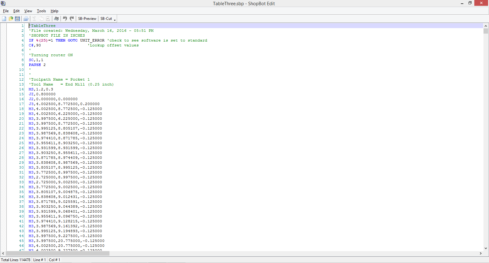
Finally I exported my toolpaths as G code so that the Shopbot could cut my design. |
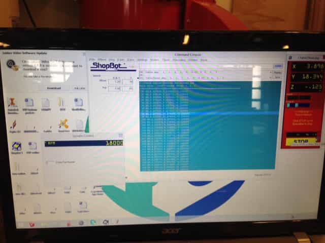
All of the rest is done through the Shopbot software. It is important to remember to do the spindle warmup routine if the Shopbot hasn't been run recently. Next the cut file can be loaded into the program. Another key thing to remember is once you hit cut and start the spindle movement, but before you have the machine start cutting the file open the manual spindle speed tool in the Shopbot software. You will often see that even though you set the spindle speed to a certain number in the cut paths settings in Aspire the spindle speed will be different in real life. Simply manually type in the desired spindle speed and you will hear the speed adjust on the machine. Then you can tell the machine to start actually cutting out your design. |
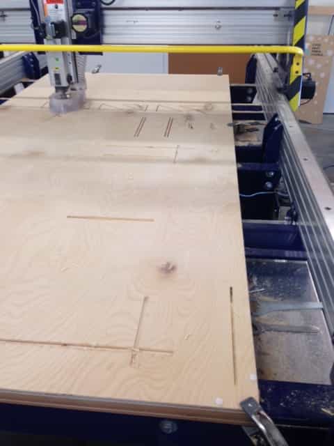
Here you can see the Shopbot cutting out my standup table design. Make sure you don't lean on the rails of the Shopbot while it is cutting because the linear gears for 2d movement are below those rails and you could easily get a finger or clothing caught while the machine is moving. |
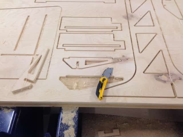
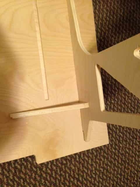
Once I am done cutting something on the Shopbot I like to use a razor blade to cut the tabs and free the parts from the original piece of plywood. Then I used a file and sandpaper to remove the parts of the tabs still left on the parts. Next I press fit the joints together. I used a mallet and in some cases found it helpful to round the edges of parts being fitted into notches so that the finished layer of the plywood didn't peel. All in all the table went together smoothly though. |
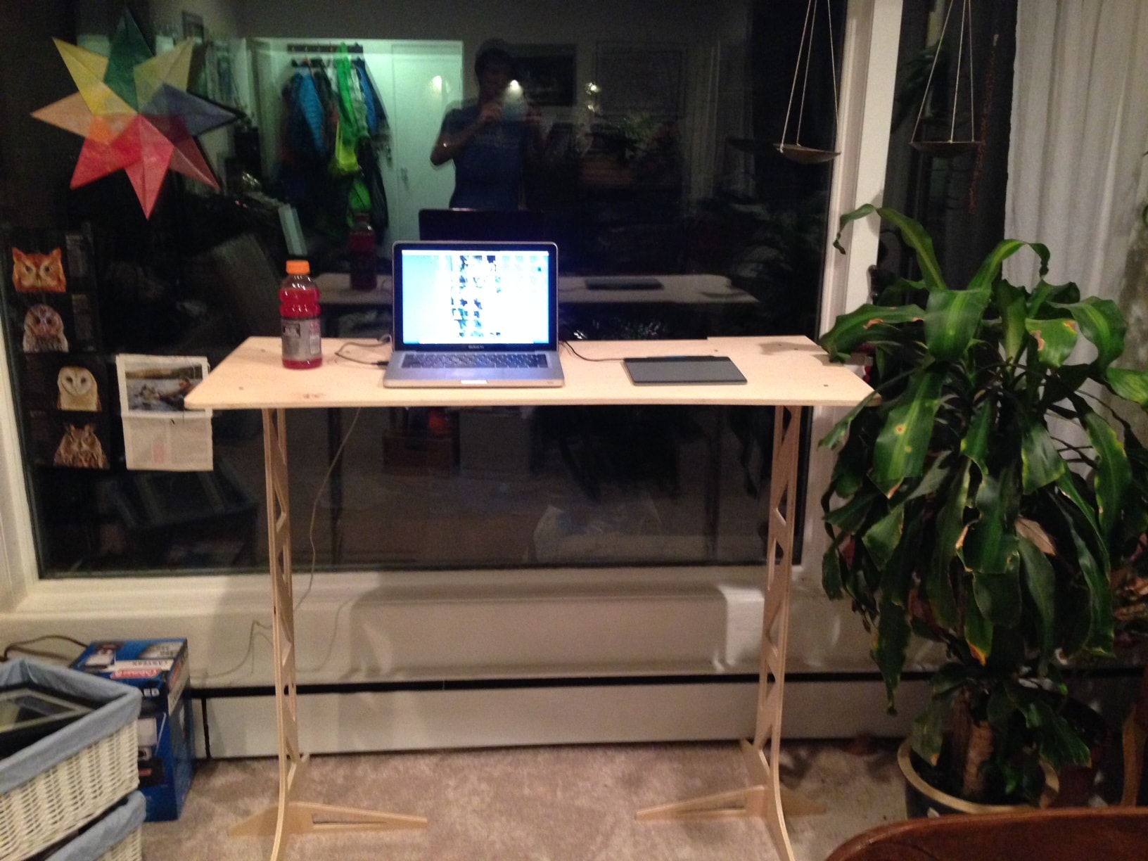
Once I finished I set up the desk infront of the window in my living room like I planned and hooked up a laptop to work at the desk. All in all I liked the process and really enjoy working standing up. For anyone else want to make a stand up desk you can download my Solidworks file here. I would recommend using slightly thicker plywood especially for the legs to reduce wobble in the desk. I would also recommend increasing the size of the leg supports both on the top and bottom to again decrease wobble. For my final project which at this point will probably be some sort of height adjusting standup desk I plan to use milled alluminum for the legs to completely eliminate wobble in the desk. Another cheaper, more simple solution is to use two vertical pieces for each leg that are both vertical, but are perpindicular to each other. This would give the desk more strength left to right, and eliminate wobble. |
This week I will go through how to program AVR micro controllers through Linux. I am using Linux Mint and will assume you are to, though most of these steps should work for other Linux distributions. On Linux the process is suprisingly simple and straightforward. |
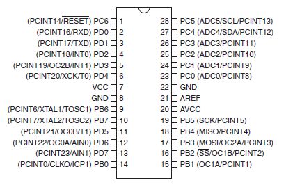
One very important step before you program a microcontroller is looking at it's datasheet. The most important pieces of information a microcontroller datasheet will give you include pinouts, operating voltage, clock, memory, and more. It is also good to keep an image of the pinouts of the microcontroller you are working with close by for reference. |

Most of the work will be done in terminal through AVRDUDE and a GCC compiler. If you have not used your computer to program AVR micro controllers before and are just getting started the first step is to set up teh toolchain for programming. Simple type the following command into terminal. |
sudo apt-get install avrdude avrdude-doc binutils-avr avr-libc gcc-avr gdb-avr |
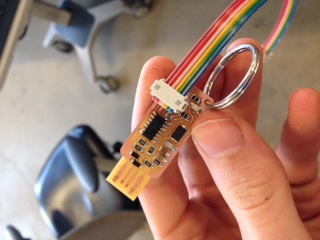
Next get an AVR programmer of your choice. I like to use the Fab ISP as well as the Atmel ICE programmers. Plug the programmer into your computer and into you circuit. |
Once that is setup check that your computer recognizes your programmer (you can use the command lsusb to check for usb devices in Linux). Then type the following command into terminal. |
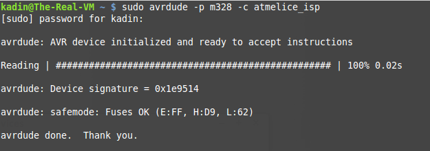
sudo avrdude -p m328 -c atmelice_isp |
If you are not using the Atmega 328 and an Atmel ICE programmer you can simply change the 328 to your chip (ex. Atmega168p would be m168p) and the atmelice_isp to your programmer (ex. usbtiny). If all goes well you should see the same response as in the image above. |

The next step is navigating to the folder that contains your makefile and software. You can use cd ... to move into folders and ls to view what each folder or directory contains. Here is a generic makefile that I have customized to meet my needs. Feel free to use this one just remember to change the programmer and processor in the makefile if you are using different ones than me. |
Now onto the final step. Once you are in the folder that has your code and makefile simple type the following command into terminal. |
make flash |
hopefully you get a similar response to the one above. After this step is done your file should have successfuly been pushed to your micro processor. |
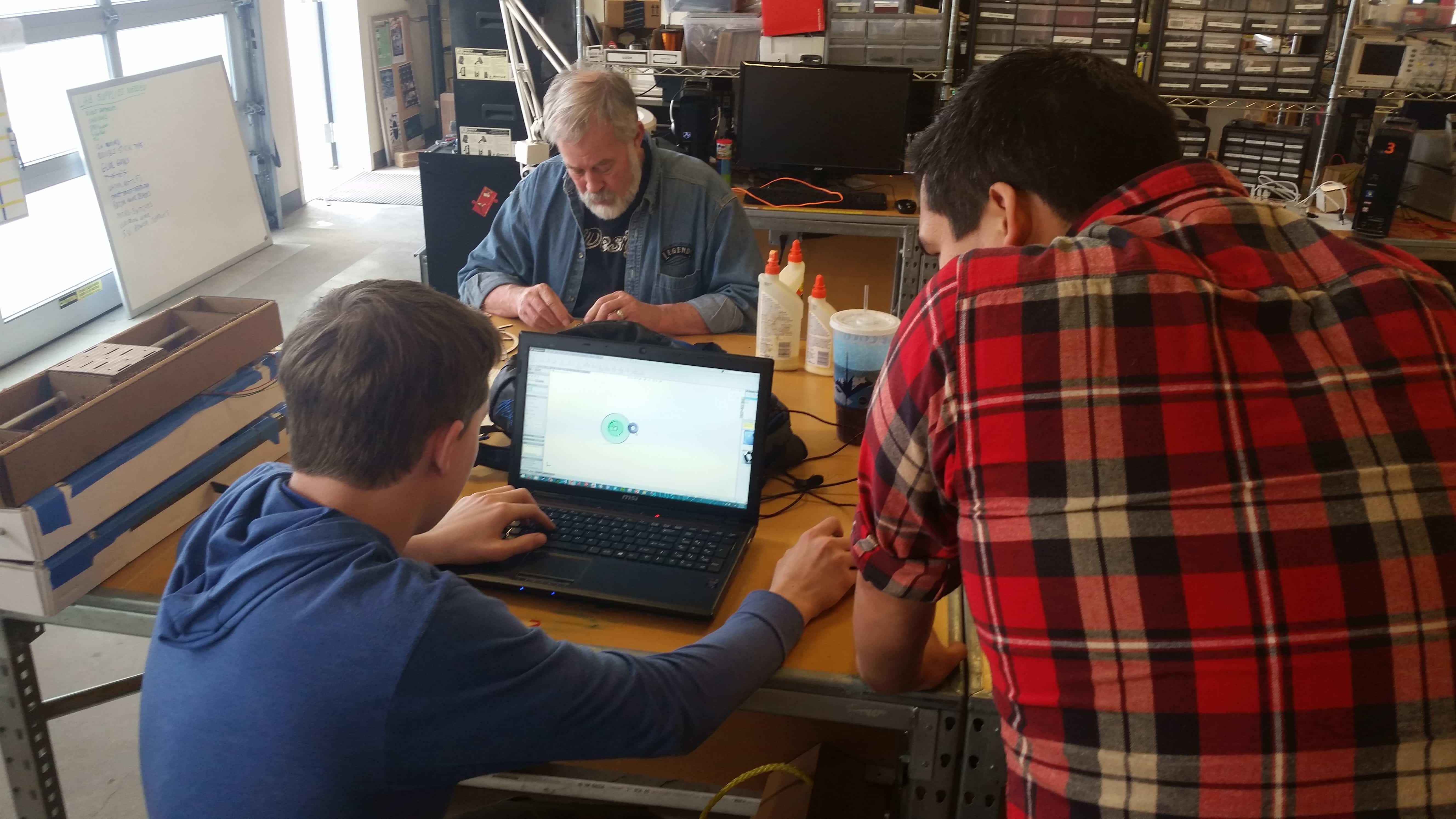
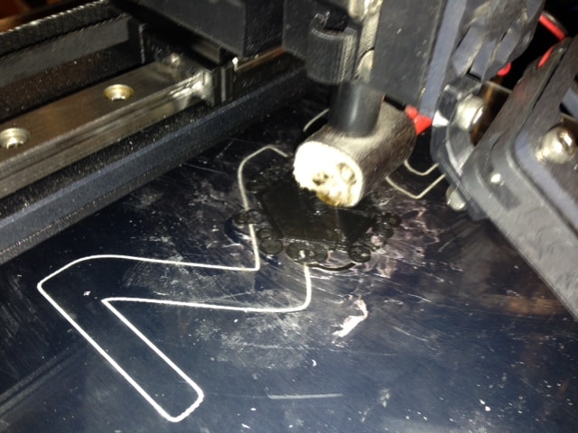
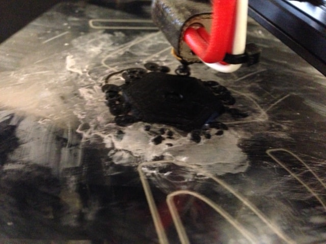
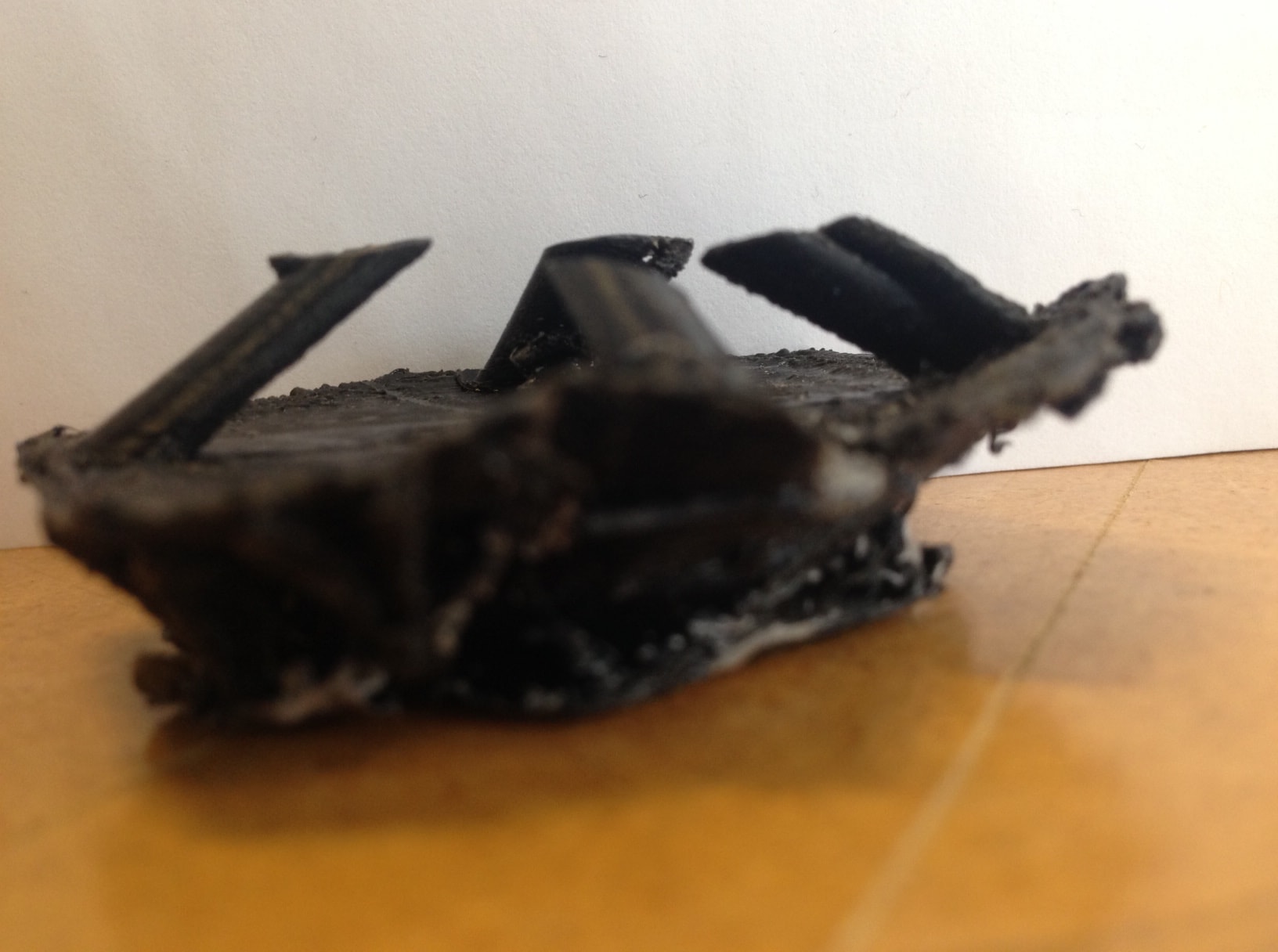
This week I am working with the rest of the students in the Fab Lab to create a machine of some sort. We finally decided that we wanted to do something unique and fun, not just a 3d printer or cnc machine of some sort. We thought a unique machine could create something edible which would make it fun and new. Our finaly decision was a pancake printer that would make fun, edible designs. |
Due to my experience using Solidworks I, along with another classmate Sam was assigned to do the extruder design for the project. My main brainstorming challenge ended up being what type of extruder to use to accuratly extrude a viscous material. |
My first design used a worm gear extrusion system to extrude two different types/colors of pancake batter. This system seemed ideal at first but had two flaws. There was no viable way to ensure gravity did not push batter out when the worms were not spinning and second we only had one stepper motor to use for the extrusion system and therefor we could not have a dual extruder using this design. |
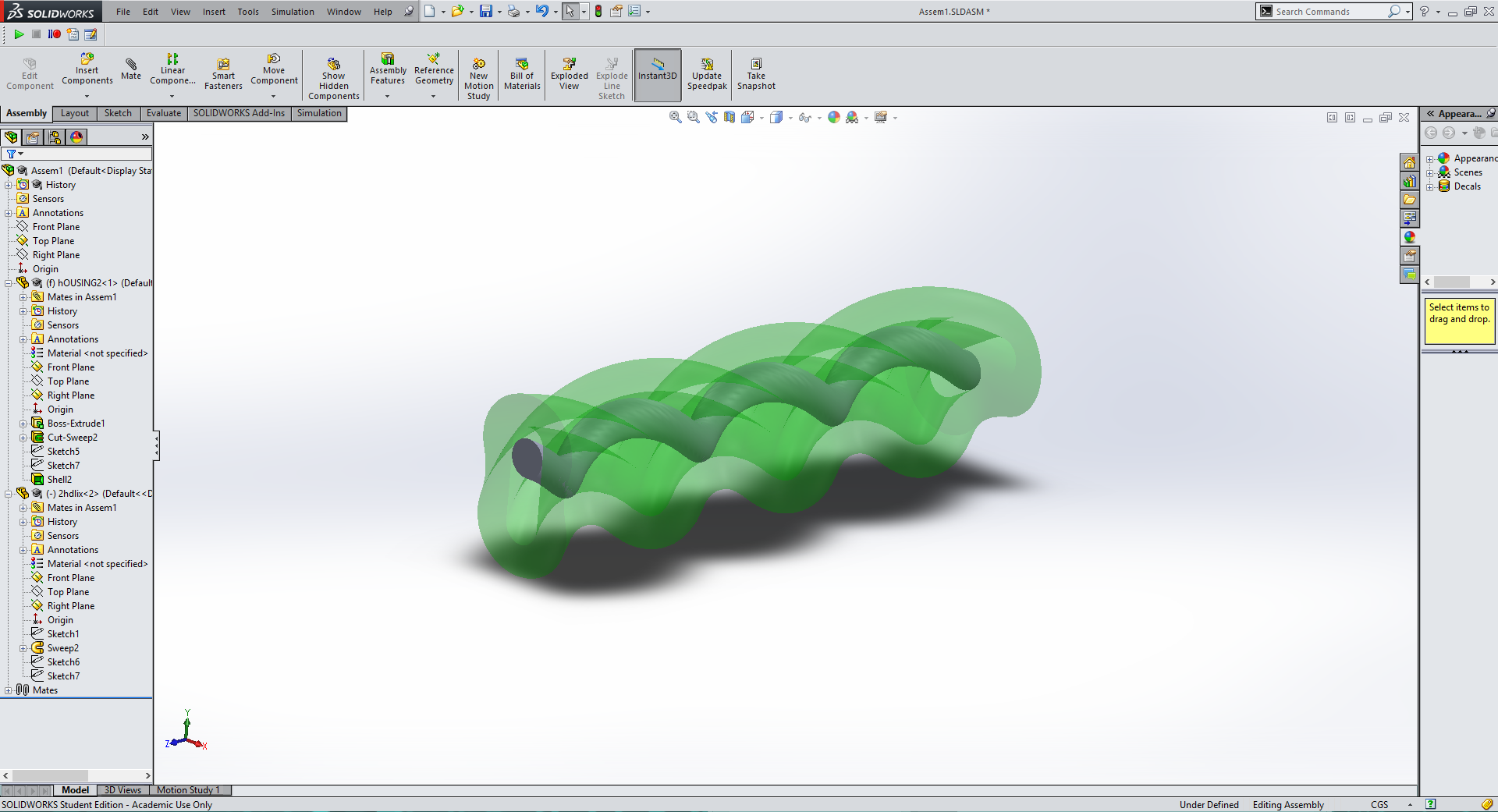
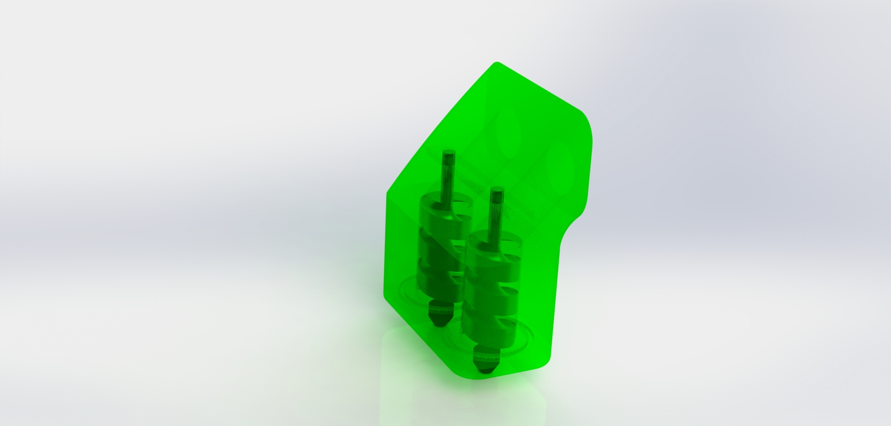
To create a more realiable extrusion system I did some research. I found that progressive cavity pumps, also known as moineau pumps are a very effective method for creating an extruder or pump for viscous liquid. There was little to no information online on designing such a pump so I had to start from scratch in Solidworks to try to design such a pump. After much trial and error here is what I found. Start with the size of shaft you want for the interior of your pump(in grey above) use this to extrude a helix of the desired length, making sure to define the pitch. Next create the stator or housing(green in above photo). Extrude a cylinder and make a slot in one end that had the same with as the diameter of your rotor, and double the high of your rotor. Use another helix of the same length, but DOUBLE the pitch to create an extruded cut. The rotor will fit inside of this cut and form a progressive cavity pump. You can use the shell command in Solidworks to make is look pretty just like in the picture above. |
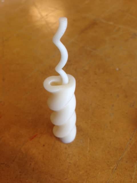
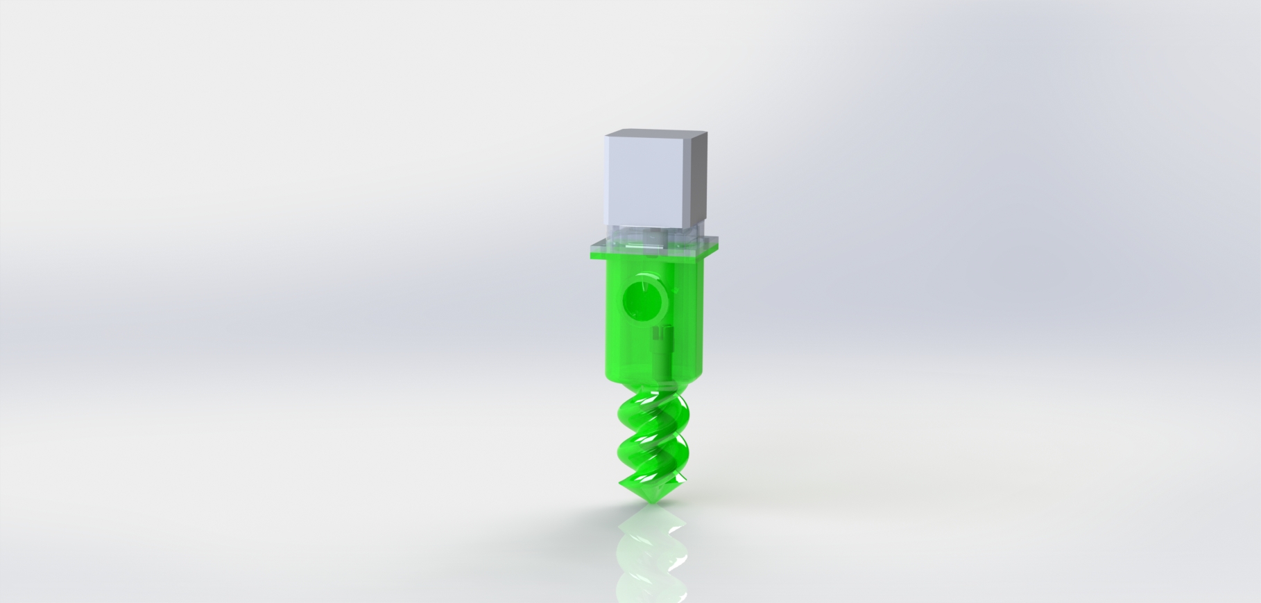
With my prototype progressive cavity pump printed and tested it was time to move onto my final design. I increased the diameter of the rotor and housing to work for pancake batter and added mounting for a stepper motor using simple joints so as the rotor moved left to right while spinning it would not break because a centered stepper motor is driving it. I also added mounting holes for the stepper motor and an hole in the side of the assemble for the pancake batter to feed into. |
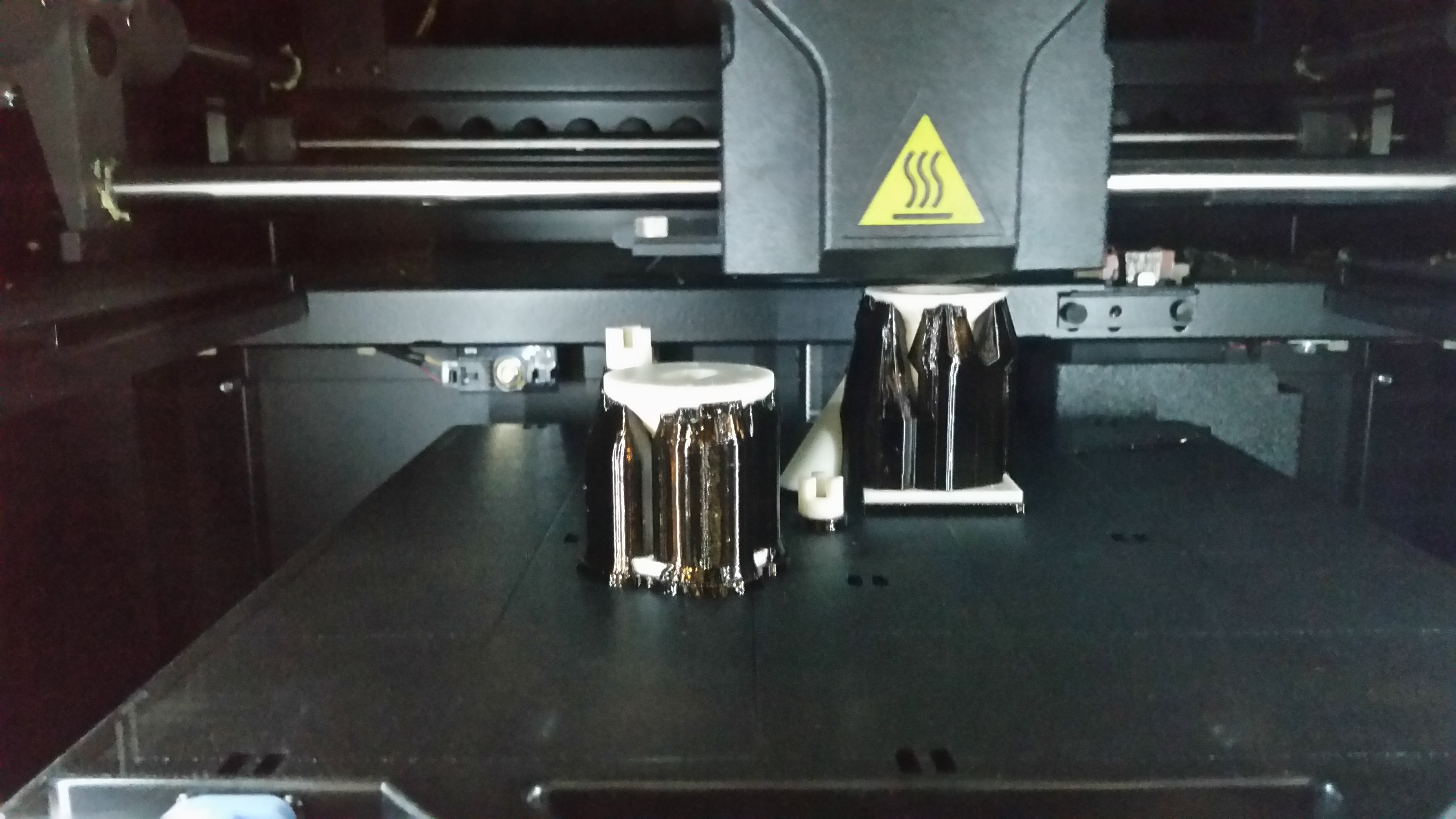
Finally once my design was complete is was time to print all of the parts and assemble them for the machine. |
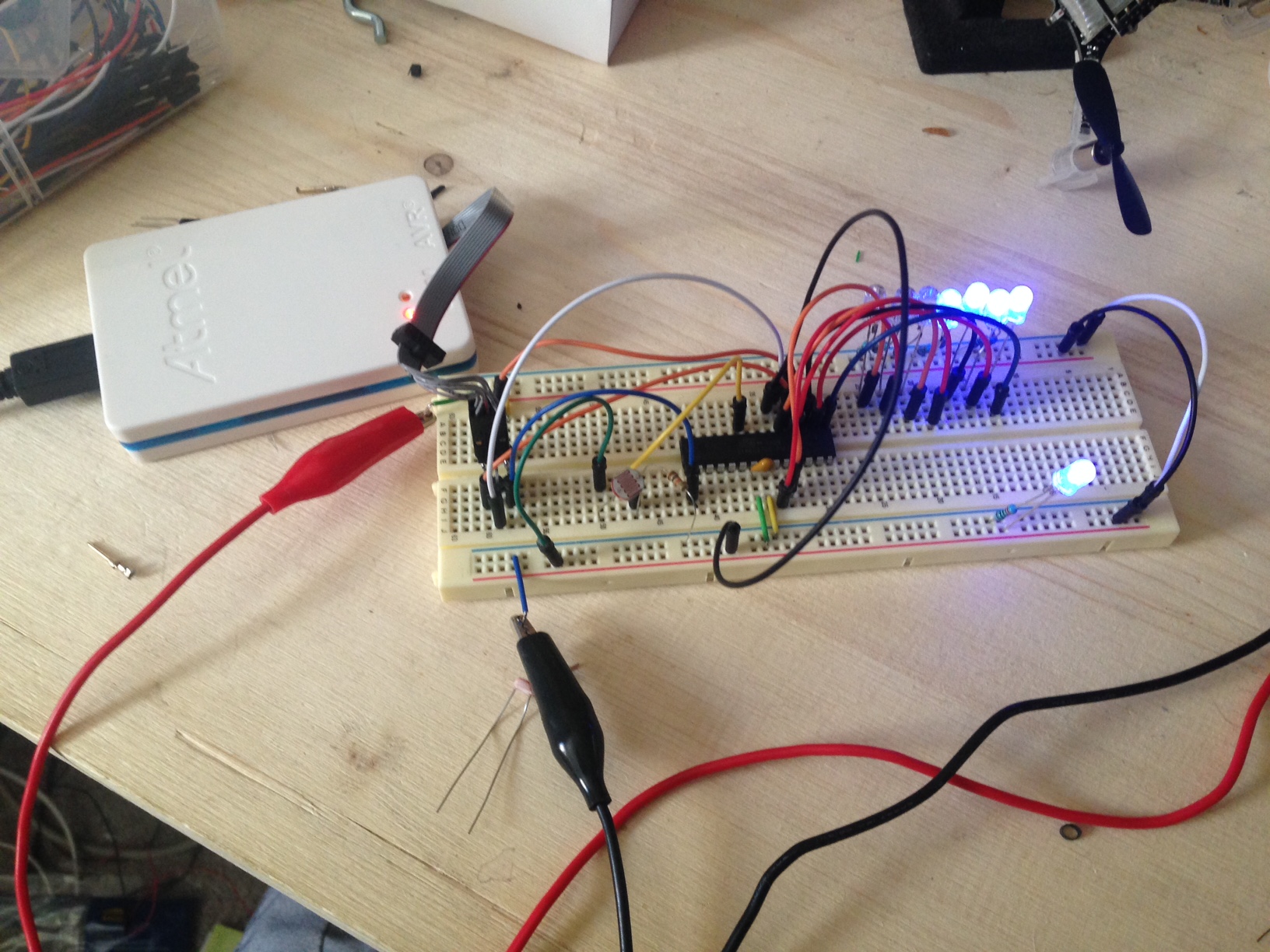
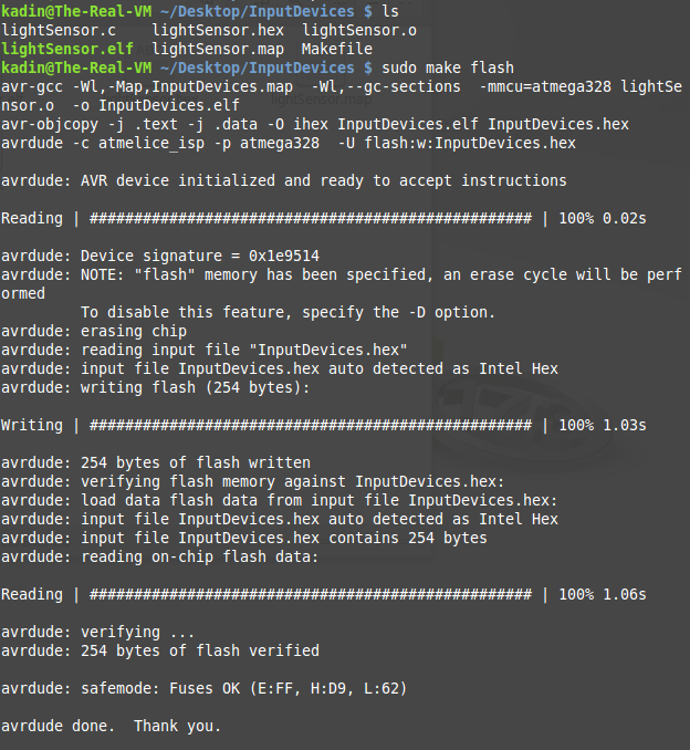
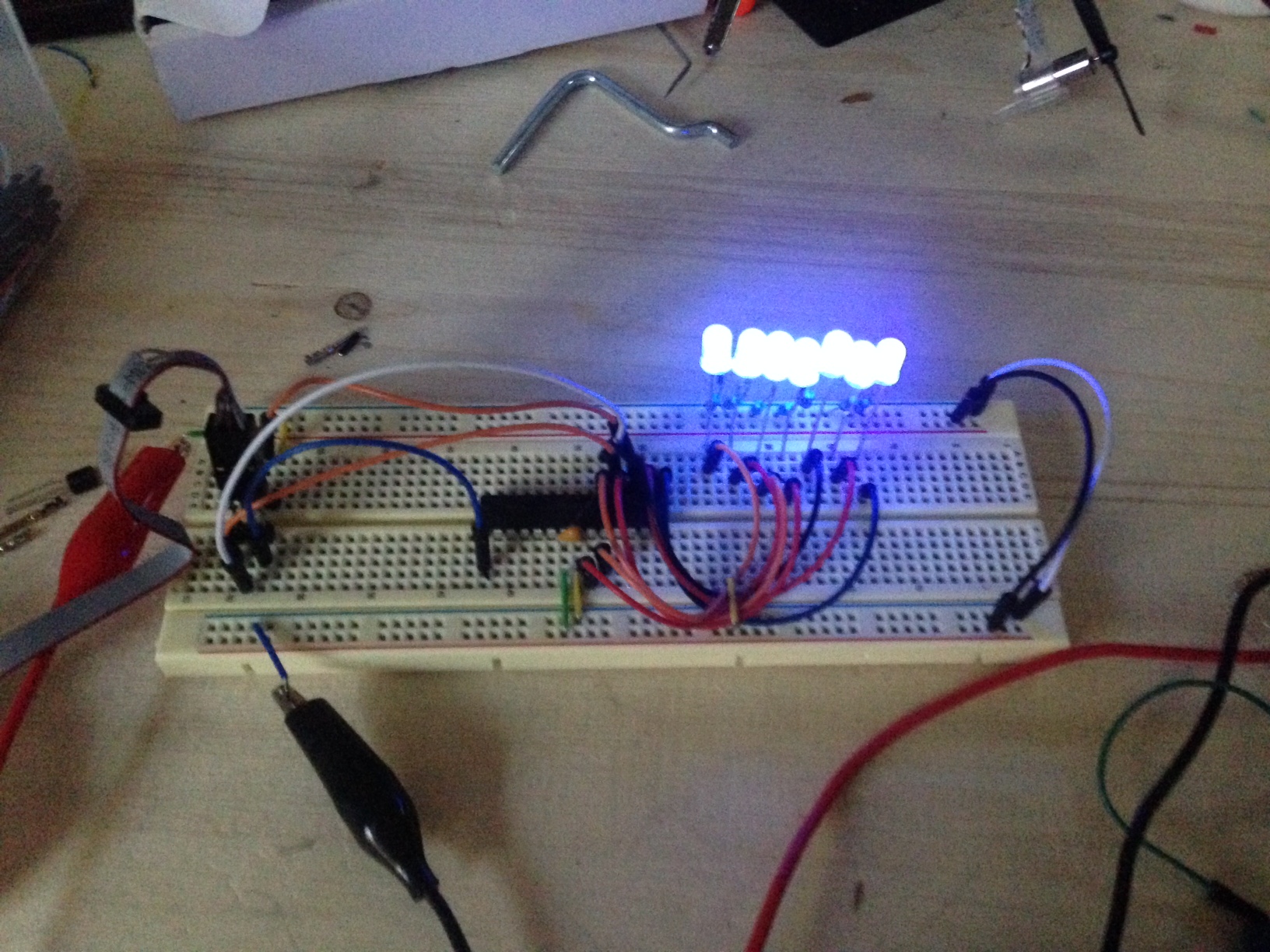
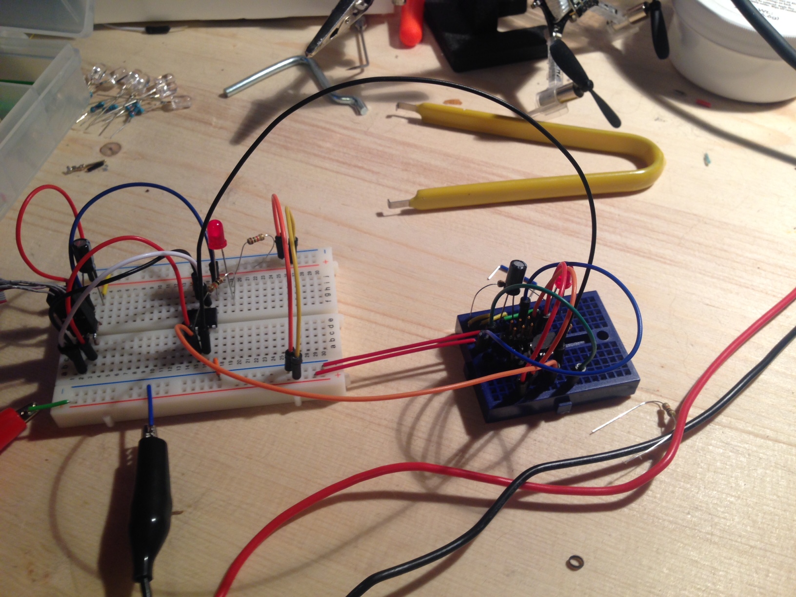
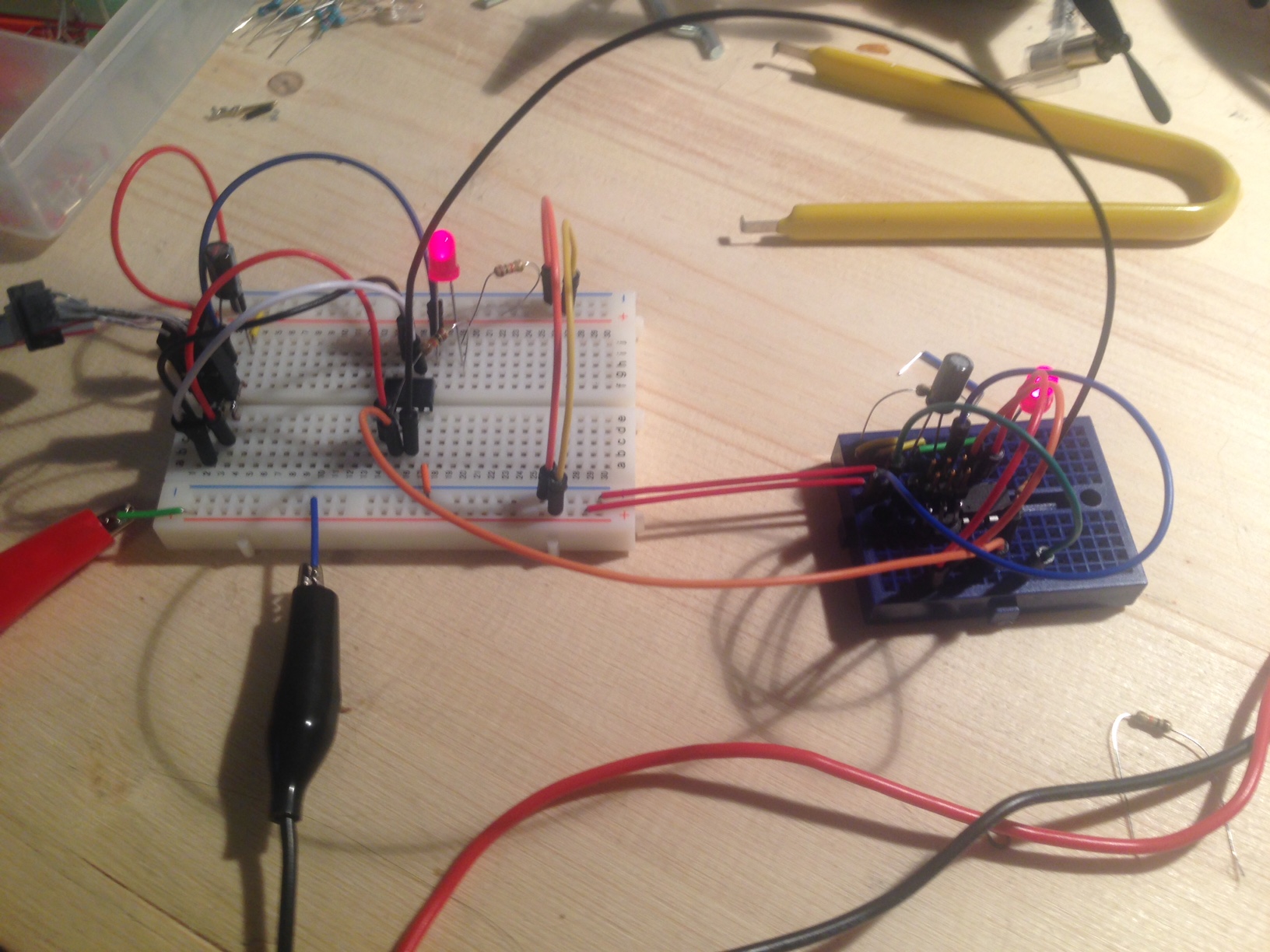
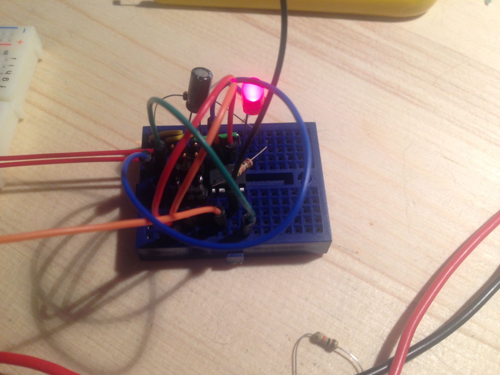
For input devices I decided to create a fun device using a light sensor. My circuit as seen above uses the light sensor/resistor to measure the amount of light and displays a general reading using a bargraph of LEDs. I would recommend checking out the microcontroller datasheet like I talked about earlier to find the operating voltage, clock, memory capacity, and pinouts for your microcontroller. It is also a good idea to keep a picture of the pinouts for the microcontroller you are using. |

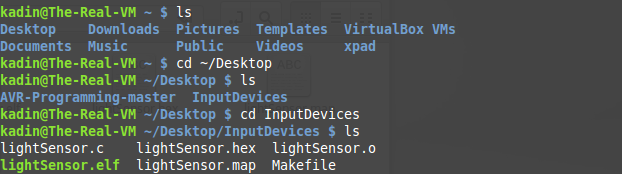

As before, to program the processor in Linux simply, check your programmer is communicating with the chip, navigate to the location of your software and make file, and finally flash the software to the processor. |
This is the result. Above is the product of my input devices circuit and software. As you can see the bargraph changes as the light changes as intended. You can get the code for this here. And the makefile here. |
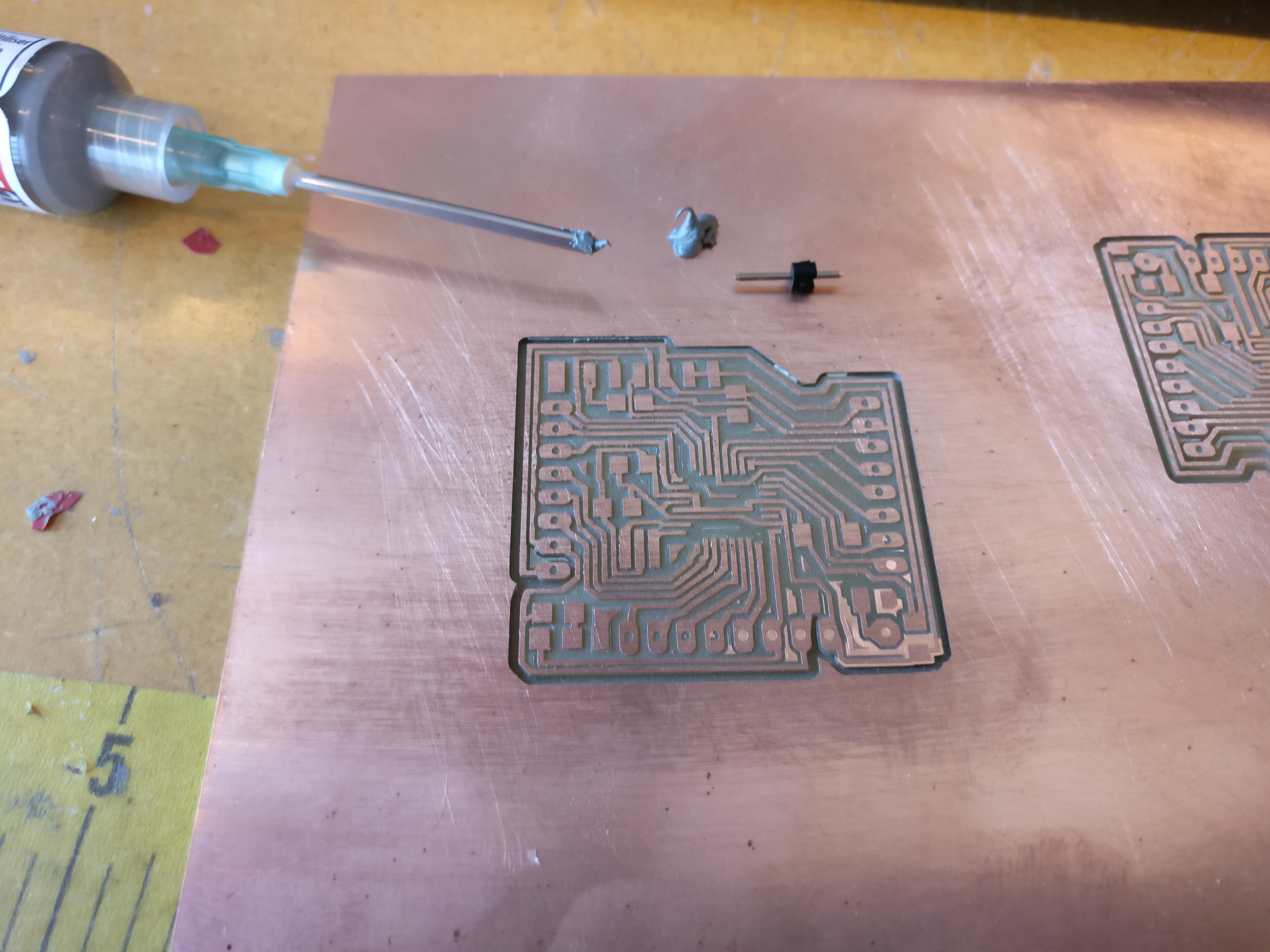
Then, once I had the project completed on a breadboard, I started cutting the pcb that I designed so I could recreate the project using a milled board. |
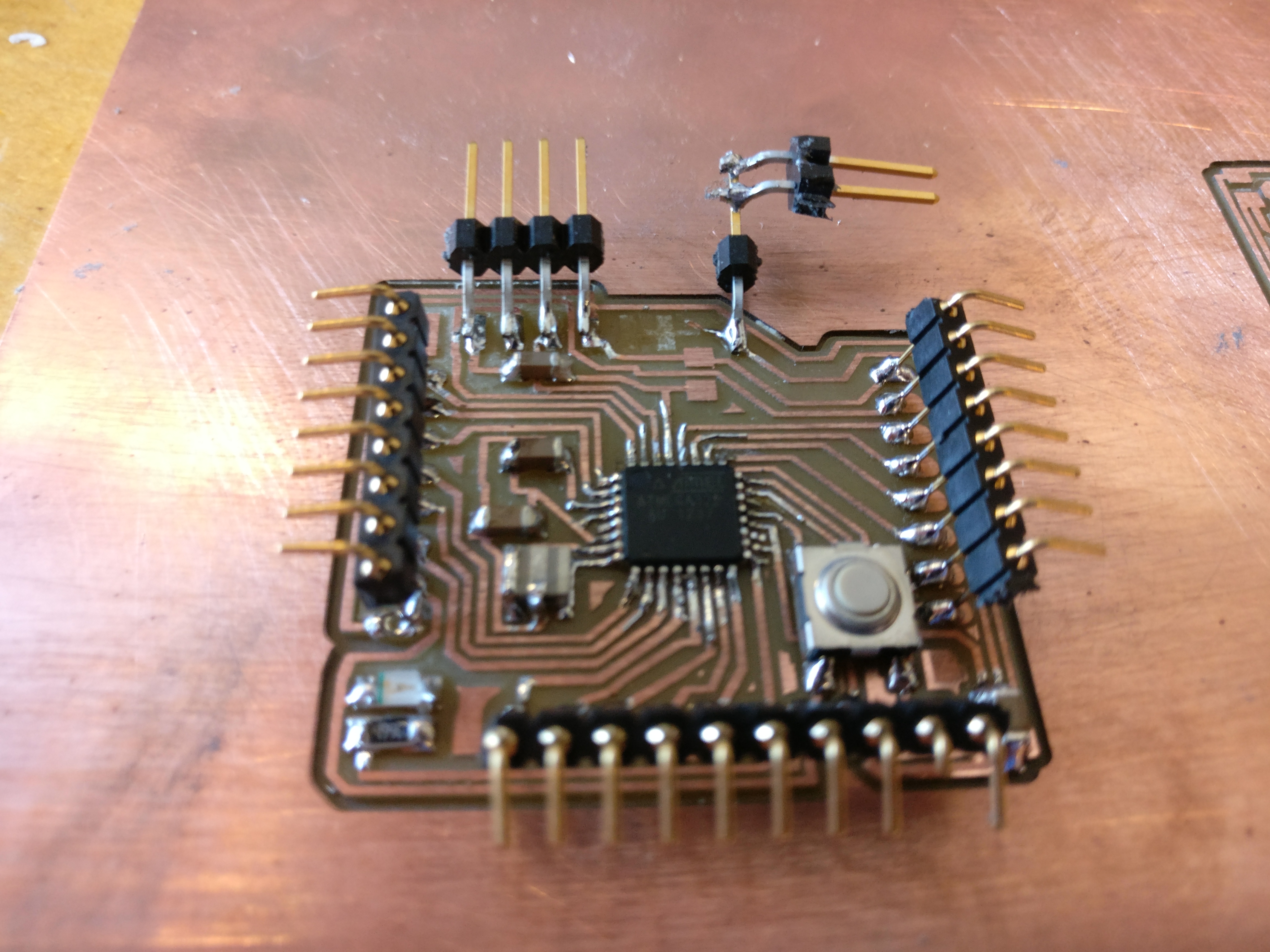
Once the board was soldered together I used it to recreate the project I had just done on the breadboard. Then I set the pcb aside for output devices. |
For this week, 3d molding and casting, I decided to focus on the process of creating a proffessional mold using a generic part to demonstrate the process. I used the Solidworks molding a casting tools to create a tutorial on making a mold in Solidworks while at the same time increasing my knowledge about Solidwork's capabilities and molding tools. You can download all of the completed files for this tutorial here. |
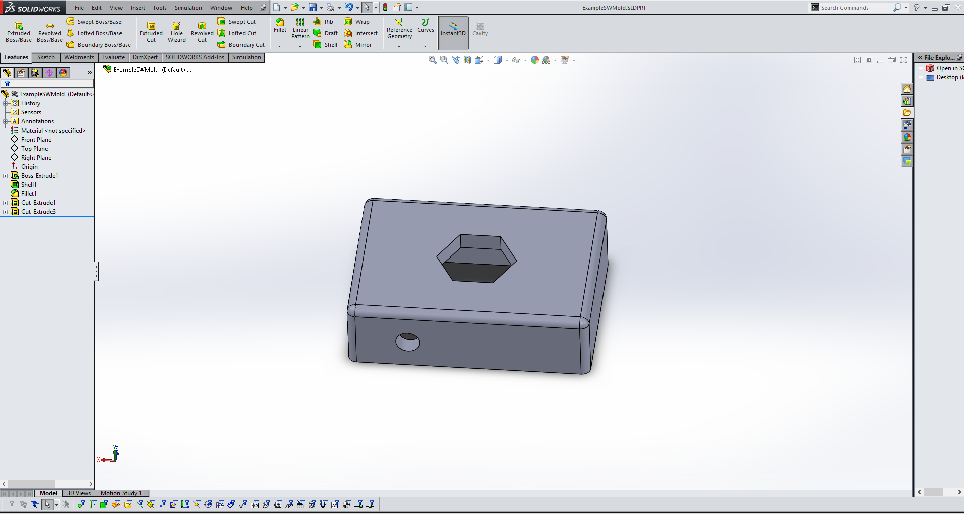
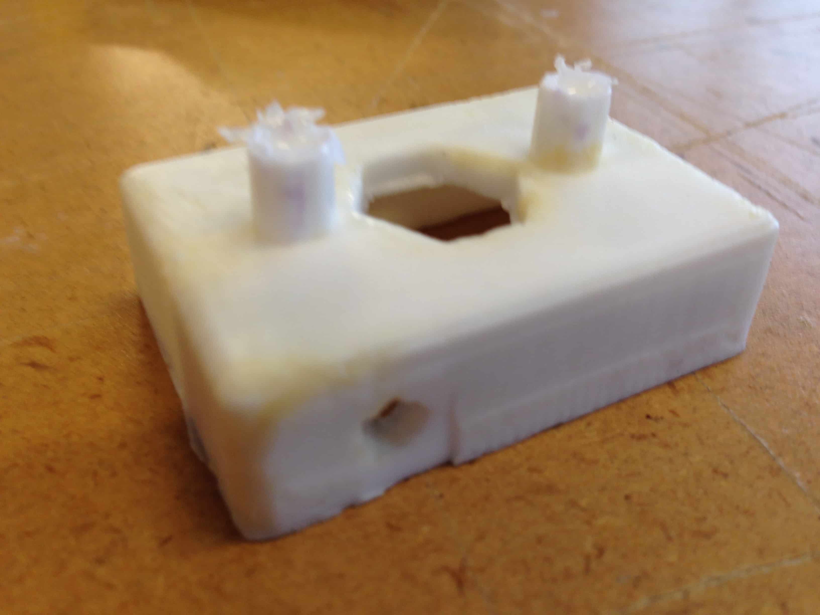
For this tutorial/project I used a very simple design to show the process. This same steps as I am going through here apply to most parts in Solidworks that you might design. My part is a simple hollow box with no bottom and two holes, one on top and one on the front. |
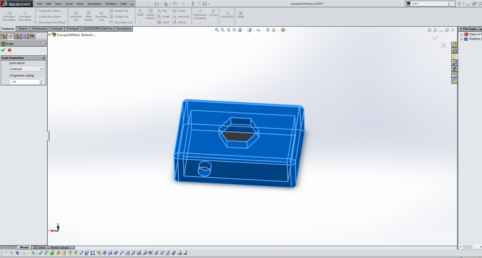
Before starting to make the mold for your part it is important to scale your part. This is important because most materials will shrink when they are cooling after being caste. This will vary based on what materials you are using, but for this project I increased by part in size by 5%. Simply use the scale tool and enter 1.05 to achieve this scaling. This 5% is a good scale for smooth cast which, according to their documentation, shrinks between 3 and 6%. |
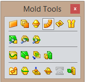
For the rest of the steps the molding toolbox in Solidworks will be used often. You can access this toolbox by searching "molding" and dragging the toolbox to any desired place on your screen. |
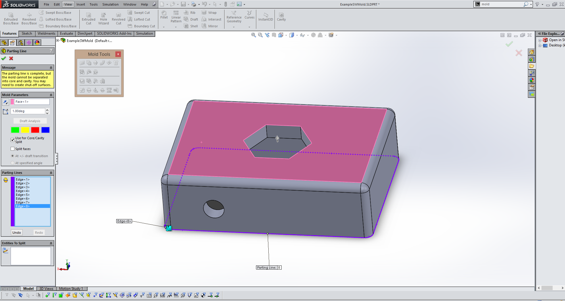
The next step is to create a parting line. This is the line/place where your mold will seperate. Simply use the Parting Line tool in the molding toolbox and select a surface parallel with your desired parting line(in pink above) and then if Solidworks does not identify a parting line(in purple above) for you select one manually. |
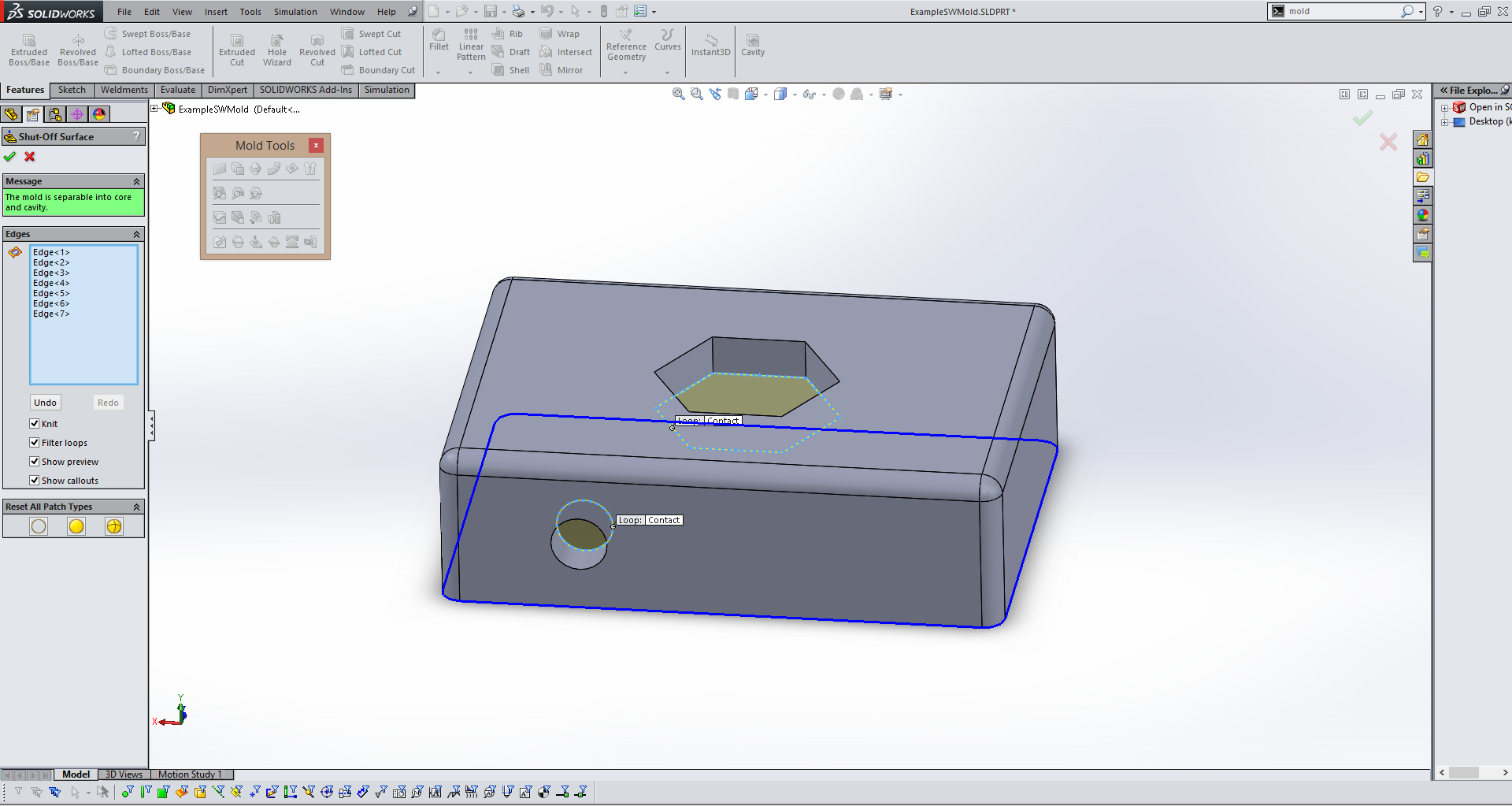
The next step utilizes the Shut Off Surfaces tool in the molding menu. This tool allows you to identify any holes in your model(in yellow above) that need to be "shut off" during the molding process. Again, Solidworks will try to identify them for you, but check to make sure it does not miss any. |
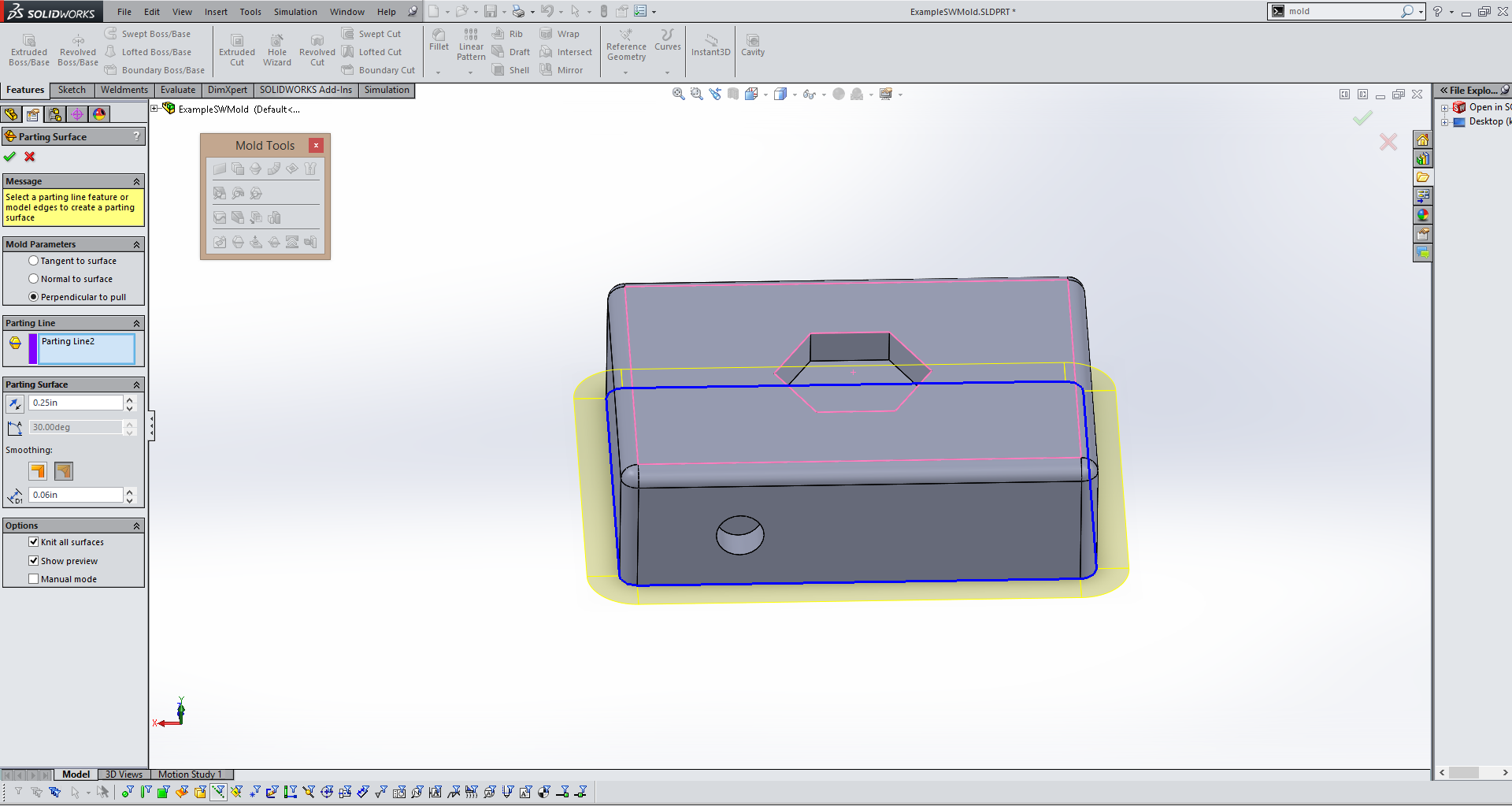
The next step is using the Parting Surface tool to define the surface where the mold will seperate. Solidworks will automatically identify the parting line and all you have to define is the size of the parting surface. I used 0.25" any value similar should be fine for this. |
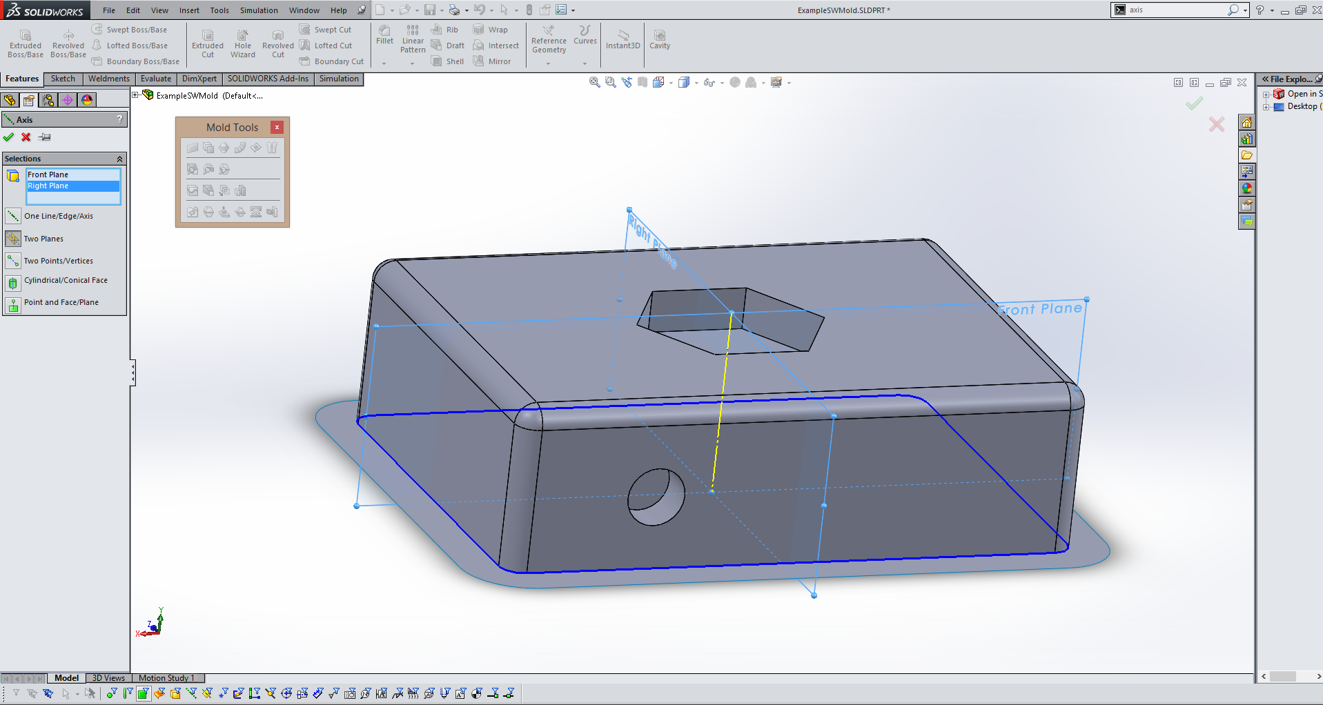
For some of the following steps we will need a reference axis. Using the axis tool create an axis(in yellow above) running perpendicular to your parting surface using two planes as refrences. |
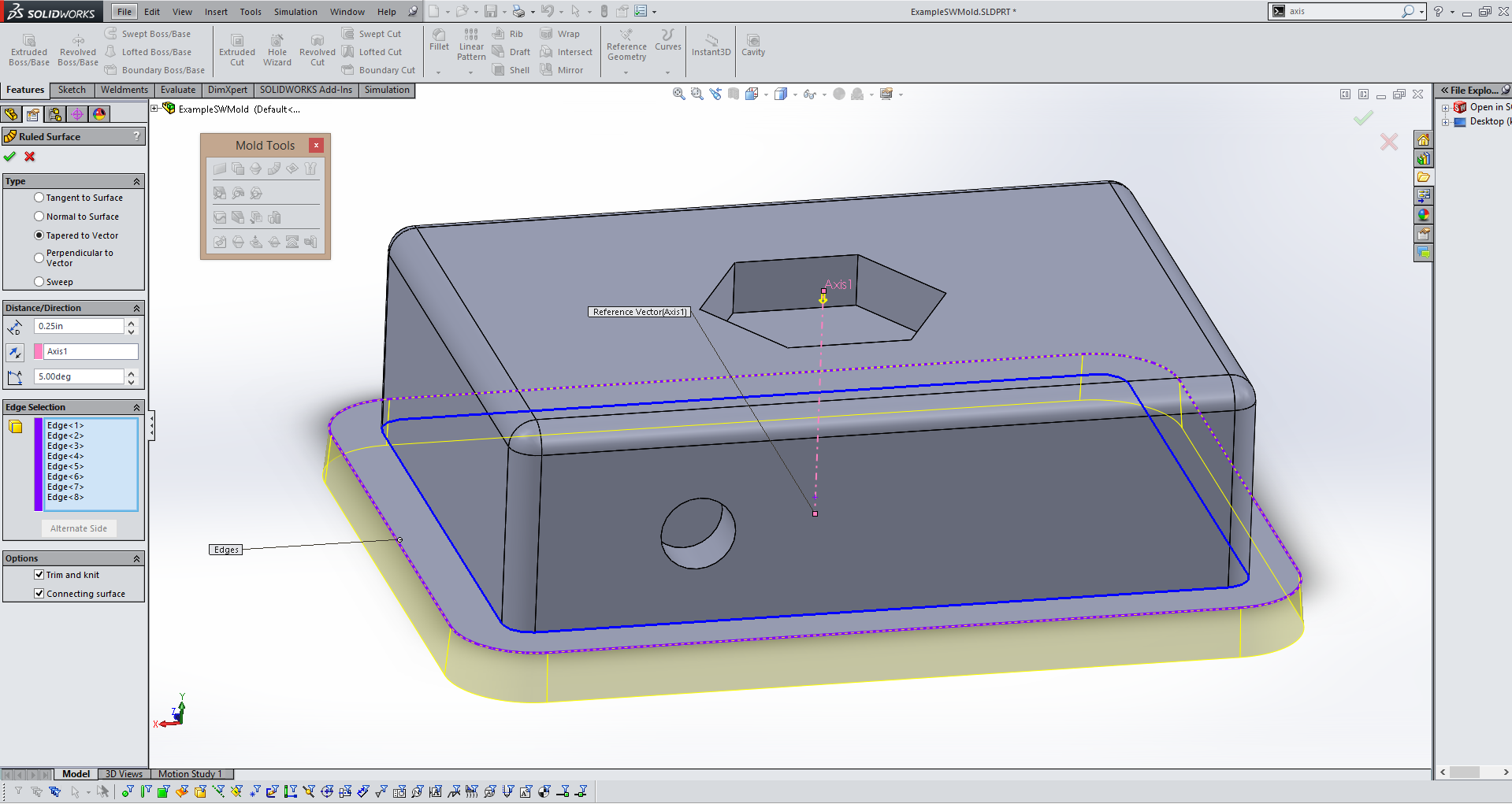
Next use the Ruled Surface tool to create a surface(in yellow above) that will help align the two halves of the mold and keep them in position during casting. Use the reference axis from the previous step to define direction and I like to use a 5 degree offset angle. Finally add a desired length, for this mold I use 0.25" to keep things simple. |
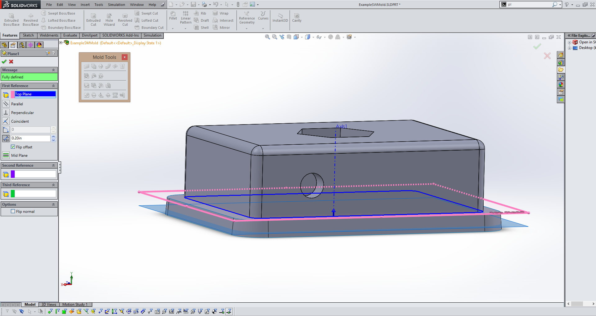
In the next step you will need to create a surface that will act as the bottom section of this mold. In order to do that you need to create a plane. Use the plane tool and the plane your part is built ontop of as a reference plan. Define an offset distance so that your new plane(in blue above) is cutting through the ruled surface you made in the last step. Since I made my ruled surface 0.25" and offset at 5 degrees I offset my plane just under 0.25" from the reference plane. |
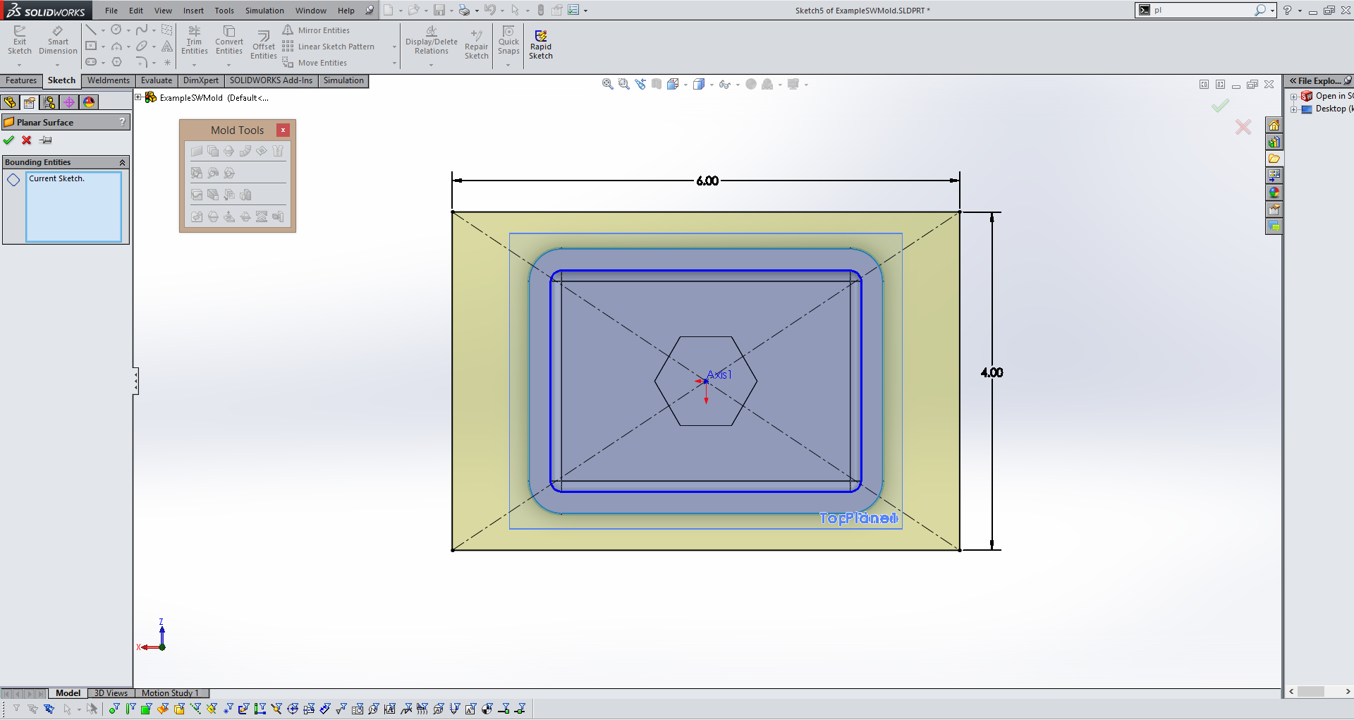
Then create a sketch on the plane you made in the last step and make a rectangle(in yellow above). Make sure it is bigger than you part, this rectangle will become the base of your core side of the mold. Use the Planer Surface tool to make a flat solid out of your sketch. |
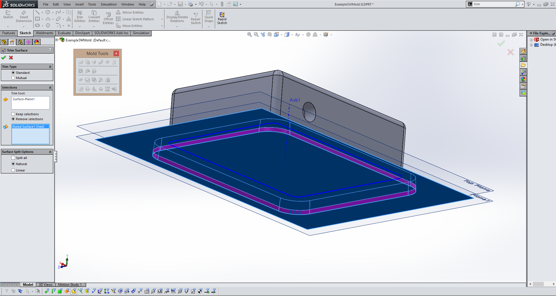
After you've create the planer surface that will serve as the base of your core side of the mold use the trim surface tool to remove the excess of the ruled surface(in purple above) that is extending past your newly created planer surface(in blue above). |
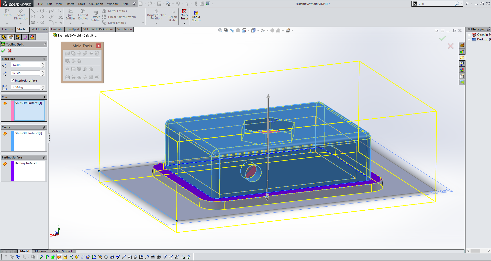
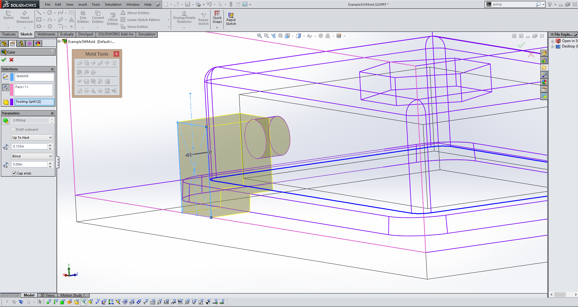
The next step is creating the two halfs of the actual mold. You do this using the Tool Split tool. First it will prompt you to create a sketch, I recommend using the plane created for the planer surface and simply using the exact same sketch as the planer surface by converting it using the Convert Entity tool. Then exit the sketch and Solidworks will automatically select the core and cavity, as well as your parting surface based on the previous steps. Define the height of the box(in yellow above) so that it is larger than you object in all dimensions. |
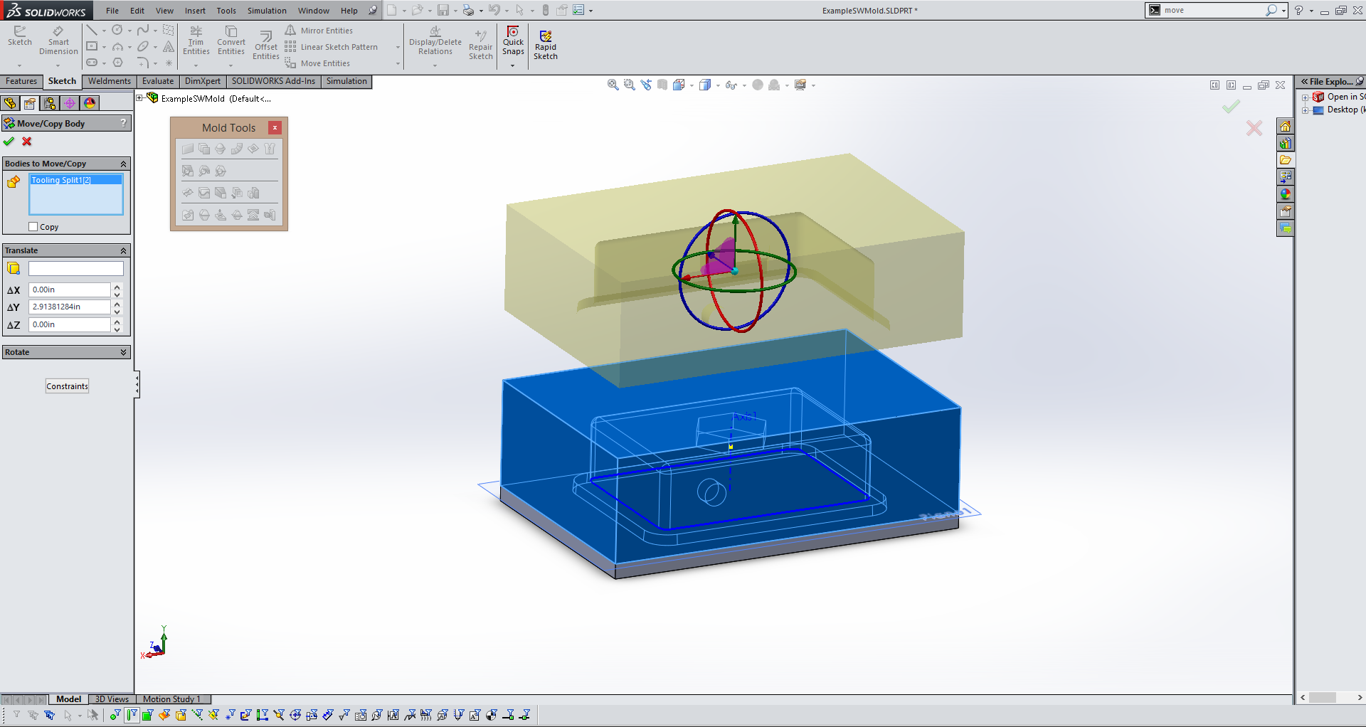
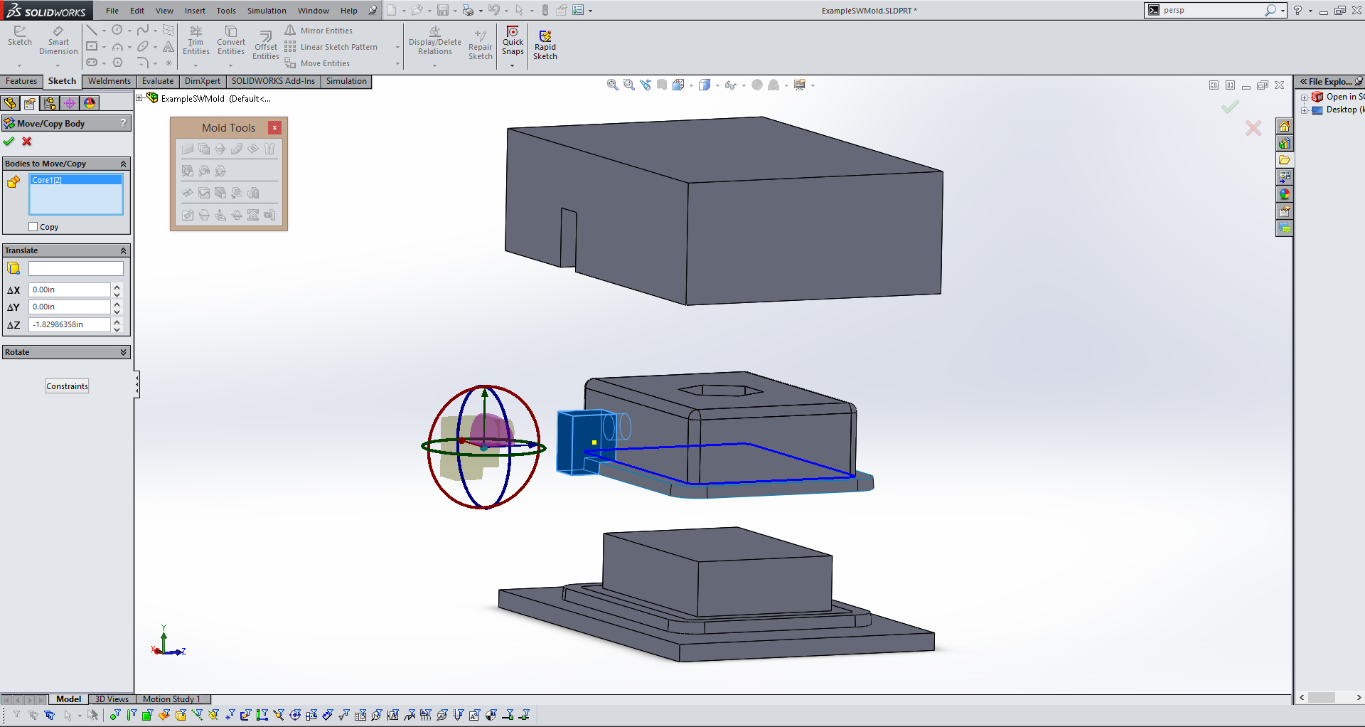
Your object will now appear to be a solid rectangle if everything has gone right so far. In order to seperate this rectangle into your cavity and core sides of the mold use the Move/Copy Body tool and drag the top section upwards(in yellow above). |
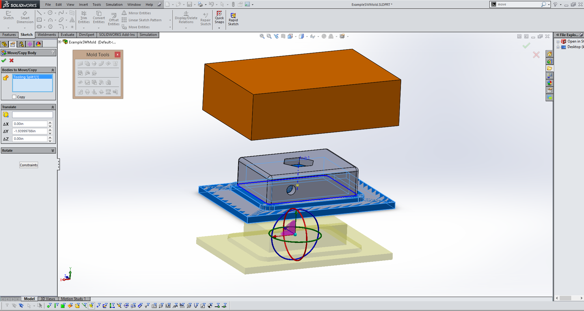
Repeat the process for the bottom section of the mold and you should see both halfs of you mold and your original part. |
This step is optional, you no longer need the planer surface that will appear to still be attached to your original part so you can click on it and select "hide" to make it invisible. |
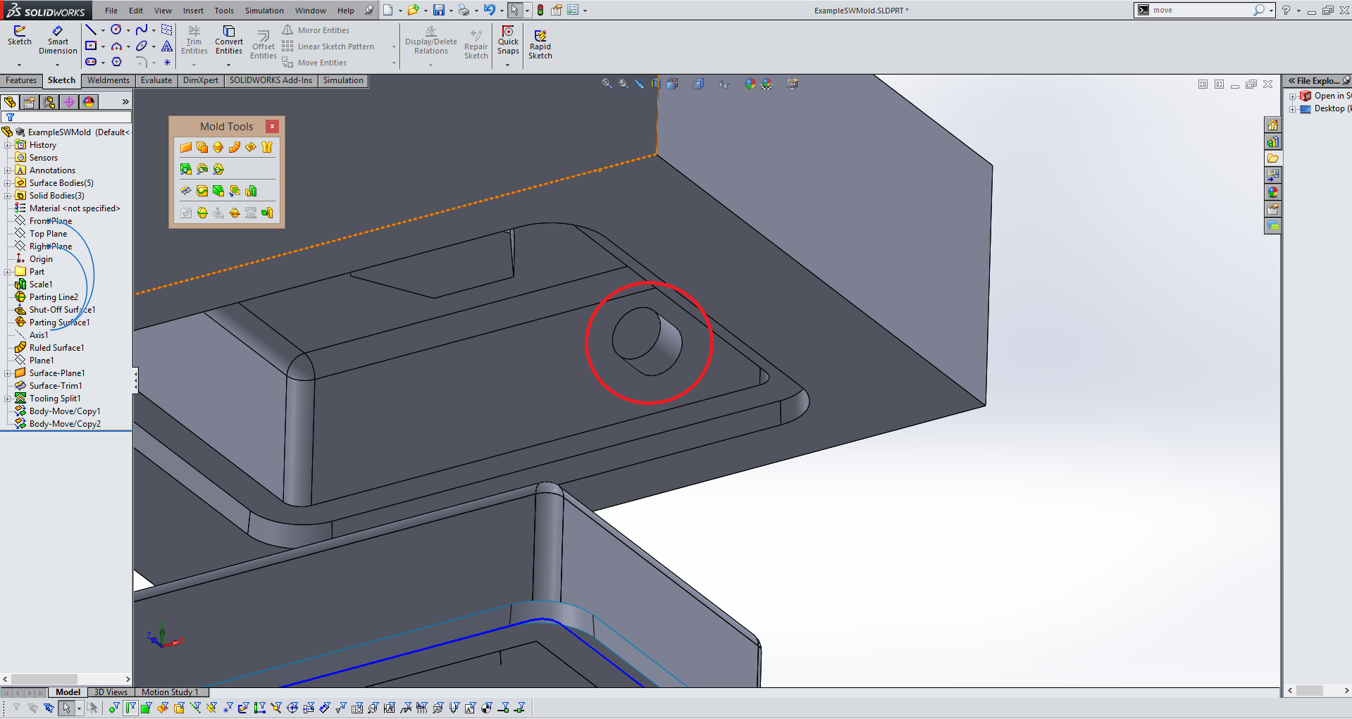
You will notice in the picture above there is an extrusion for the hole in the front of the shape(inside of red circle above) that cannot be milled if the mold is being milled on a 3 axis CNC. If any shapes or features such as this are present you will have to create core(s). |
In order to create a core it is best to revert to before you moved the cavity and core sides of the mold. Use the blue line as seen above and drag it to above the move/copy commands. This will stop these steps from effecting your part, but keep them so you can bring them back later. |
Next using the menu in the top of your work area change the part view option from shaded with edges to wireframe so that you can see interior features of your mold and part. |
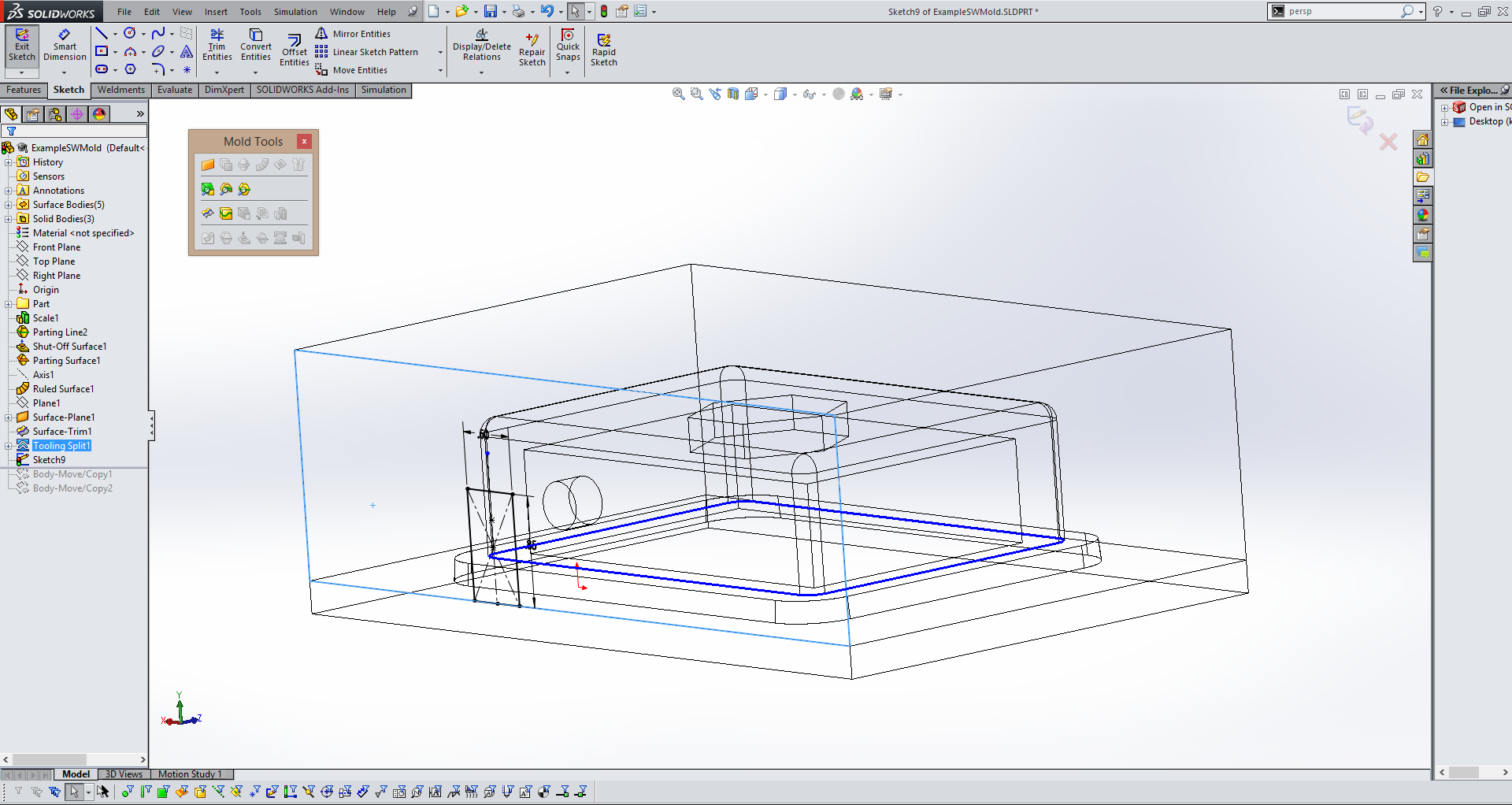
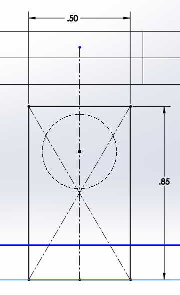
Once you select the Core tool it Solidworks will prompt you to select a surface to make a sketch on. Select the surface that is closet to the feature you identified. Sketch a rectagle that surrounds the feature that needs a core and is collinear with the line that seperates the two halfs of the mold. |
Exit the sketch and the core tool will pop up again. This step is almost like creating an extruded feature. Simply select "up to next" to tell the core that the core(in yellow above) will run from the outsideedge of you cavity side of the mold to the inside surface. |
Then you can change your model using the menu on the upper screen back to the shaded with edges view mode. |
Now that the core is complete you can use the same blue line to unsuppress the move/copy commands you used earlier to expand the mold. |
As done earlier, use the Move/Copy tool to move the core away from your part. |
This step is optional. You can hide the parting line, shut off surface, and ruled surface you created earlier because you will no longer need them. |
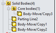
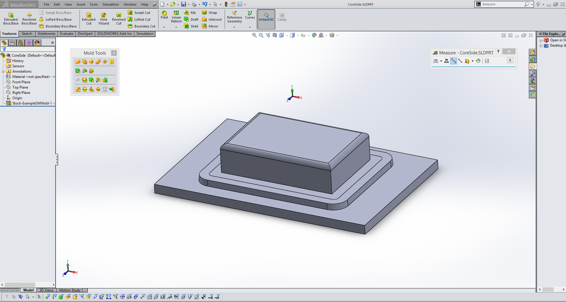
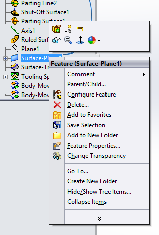
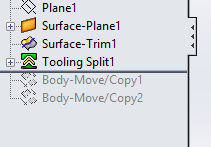
Now that you have completed all of the parts for your mold you can go into the Solid Bodies folder on the right hand side of the screen and right click on each of the parts of the mold. In this case the cavity side, the core side, and the core. You will see an option to save the body as it's own part. This will allow you to export it individually for machining. |
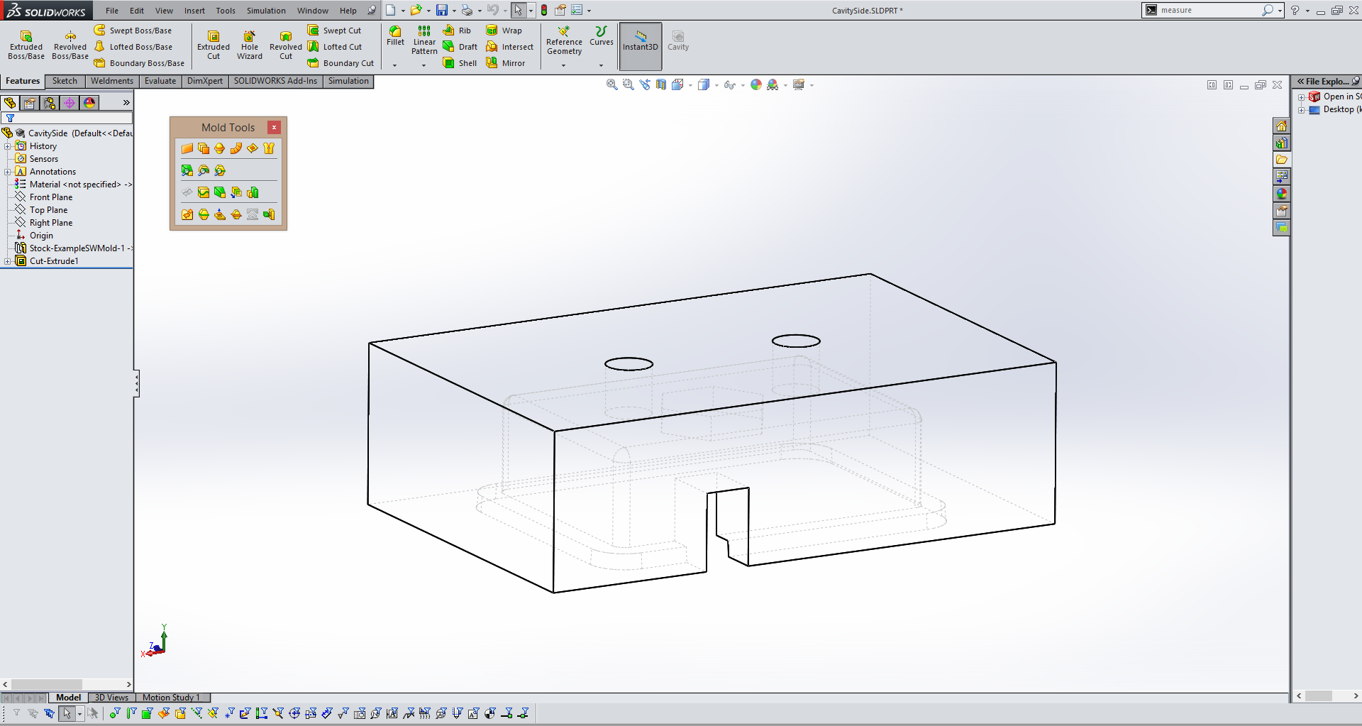
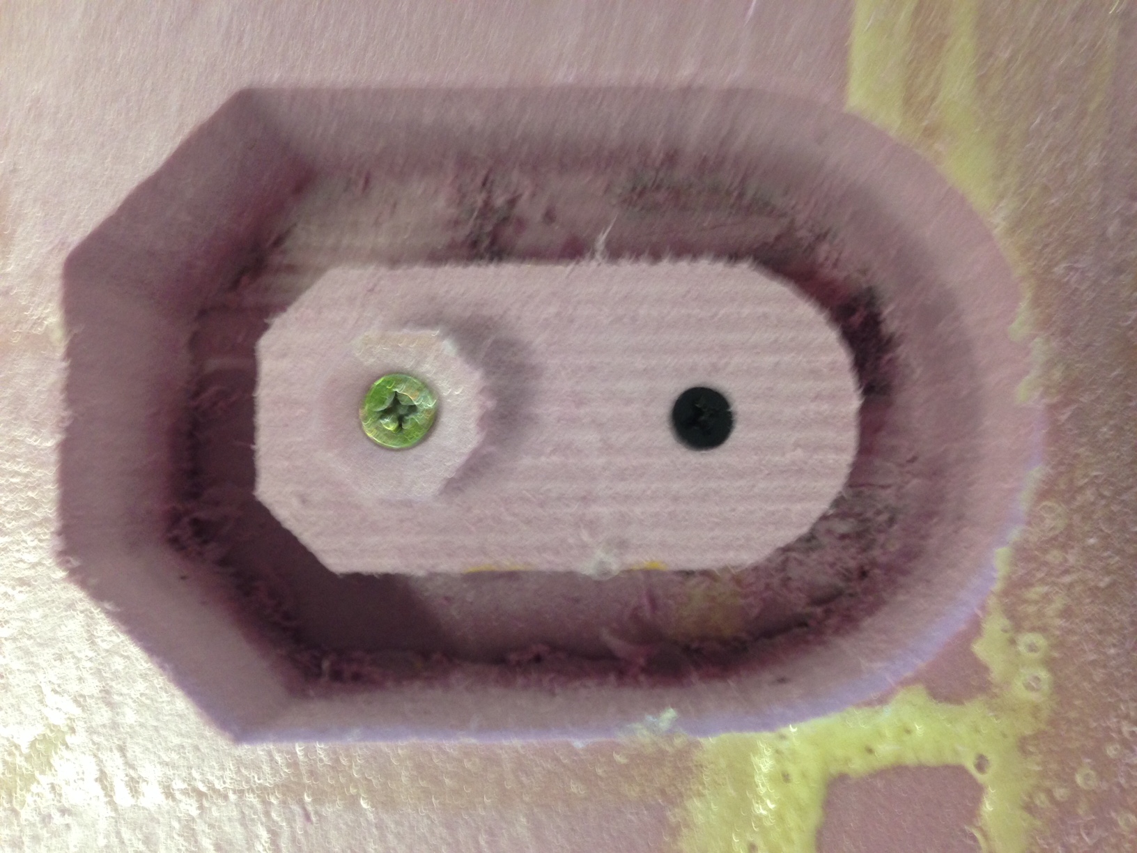
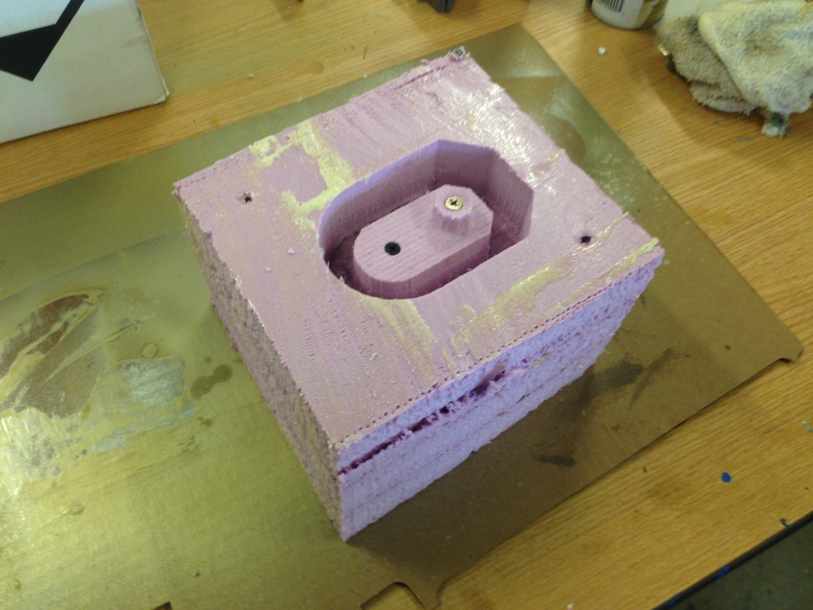
For this part I am simply going to be pouring the mold by hand so I put two holes in the top of the mold. One to pour into and one as a vent. |
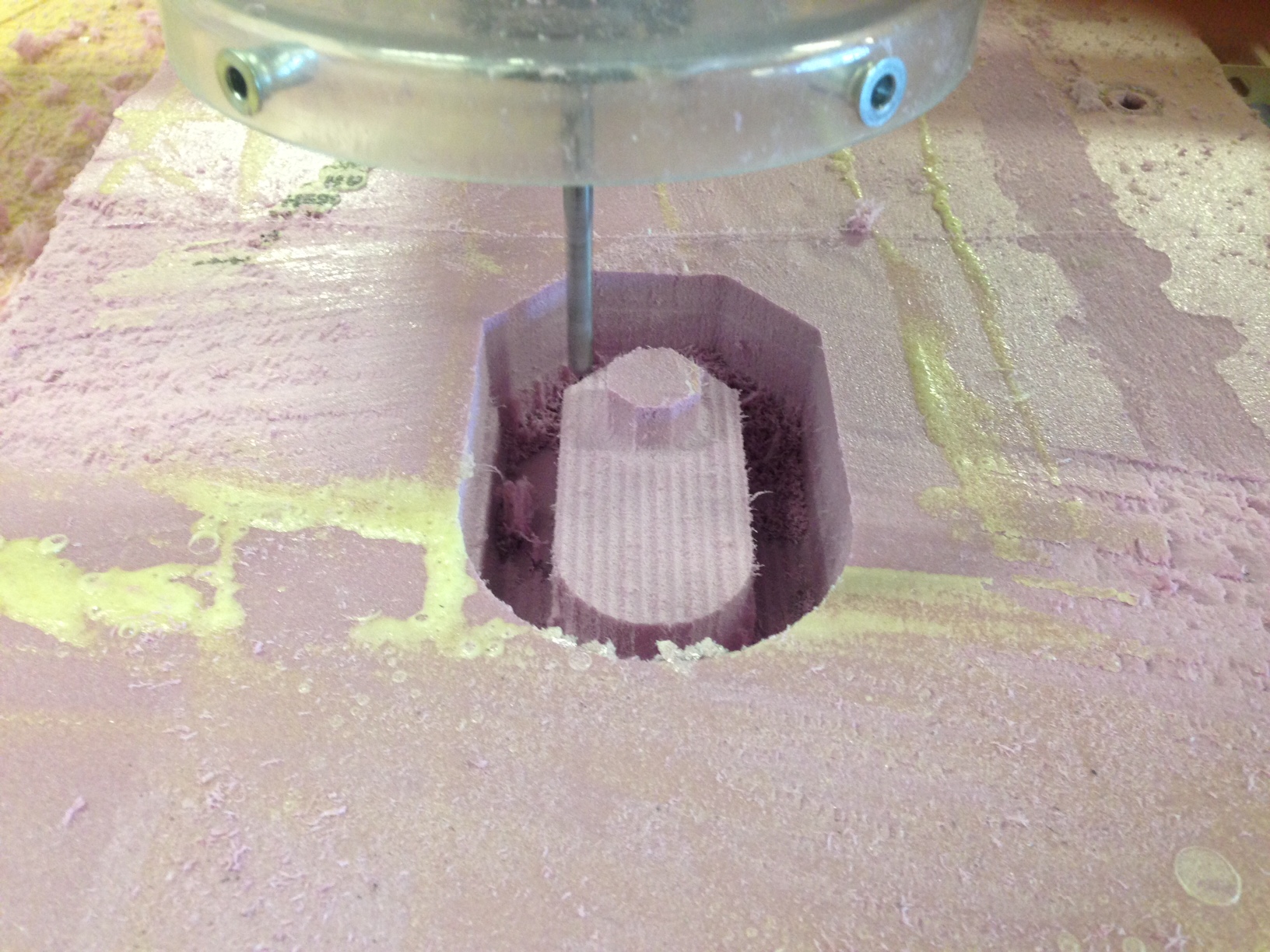
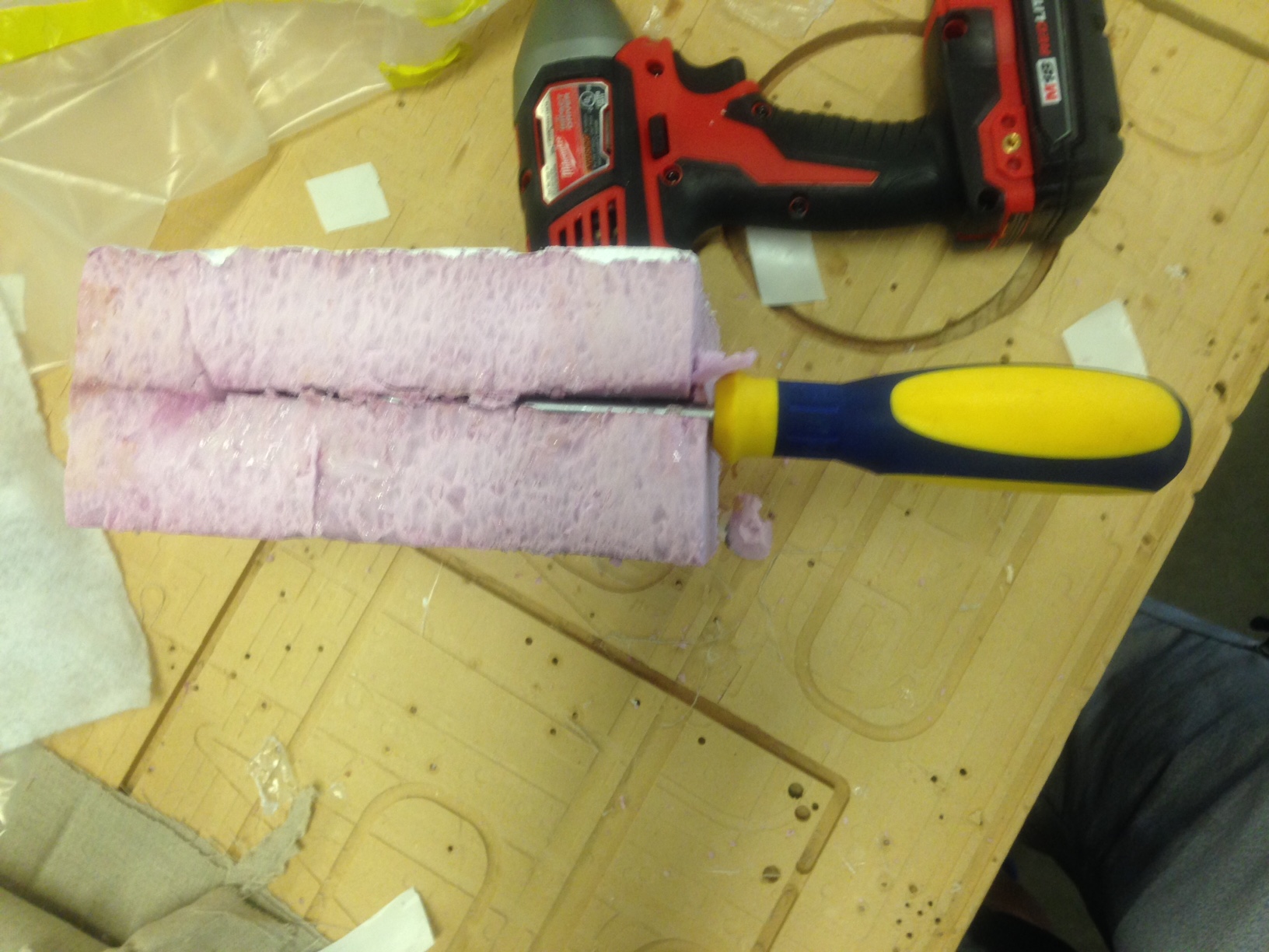
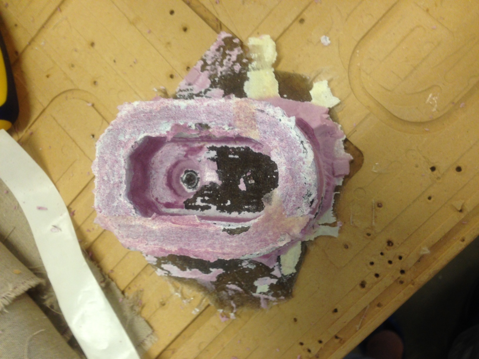
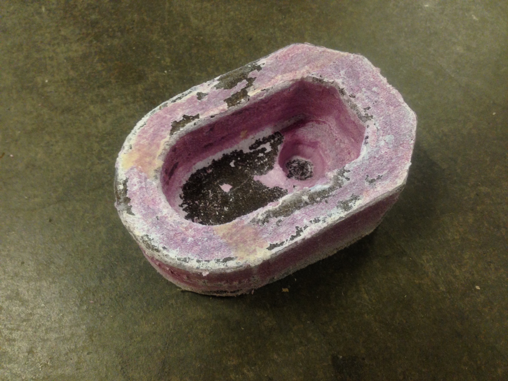
After I finished designing the mold and exporting the .stl files I open them in Aspire to begin the machining process. I created a cut file with same dimensions as my piece of wax and dragged the .stl files onto it. Then I created cut files for the 3 parts of the mold, making sure they were alligned with the bottom of the wax block. The two cut files I created were a roughing outline and a finishing cut to give the pieces an accurate finish. Next, I cut out the parts of the mold on the Shopbot in foam using an 1/8" bit. Once I put together the foam mold and was happy with how it looked I moved on to wax. I cut the parts out using the same 1/8" bit with standard settings. Once that was done I put the mold together, making sure to clamp it closed, and poured Smooth-Cast into one of the two holes I added to the top, making sure to move the mold around and let any air release through the vent hole. Since I have worked alot with epoxy and other quick setting glues the Smooth-cast set time did not bother me. It gave me plenty of time to work with and remain liquidy enough for me to almost completely eliminate all of the bubbles just by tilting the mold back and forth after pouring it. The smoothcast took between 30 minutes to dry with the 1 to 1 mix ratio of the Smooth-cast 305. |

And today I was suprised to learn that Cheetahs cannot roar :( |
For this week, output devices I decided to make a POV(persistance of vision) toy. The idea is a row of LED lights that is blinking very fast and as you shake the lights or move your eyes back and forth past the lights without focusing on them you can make them appear solid or disappear all together. During a project like this I would always recommend checking out the microcontroller datasheet for the microcontroller you are using. The datasheet will give you usefull information such as the microcontrollers clock speed, memory capacity, and pinout. |

As before, to program the processor in Linux simply, check your programmer is communicating with the chip, navigate to the location of your software and make file, and finally flash the software to the processor. |
The final product is a very cool toy that can consume you for hours as you experiment with different delays for the blinking of the lights. It is hard to really see on camera but I took a video anyway. You can get the code here. And the makefile here. |
Once I completed the project I dug out my input devices pcb and again, like in input devices, recreated the same project using a milled pcb board. |

This week, for composites, I decided to make a mounting bracket for my linear actuators that I will be using on my standup desk. |
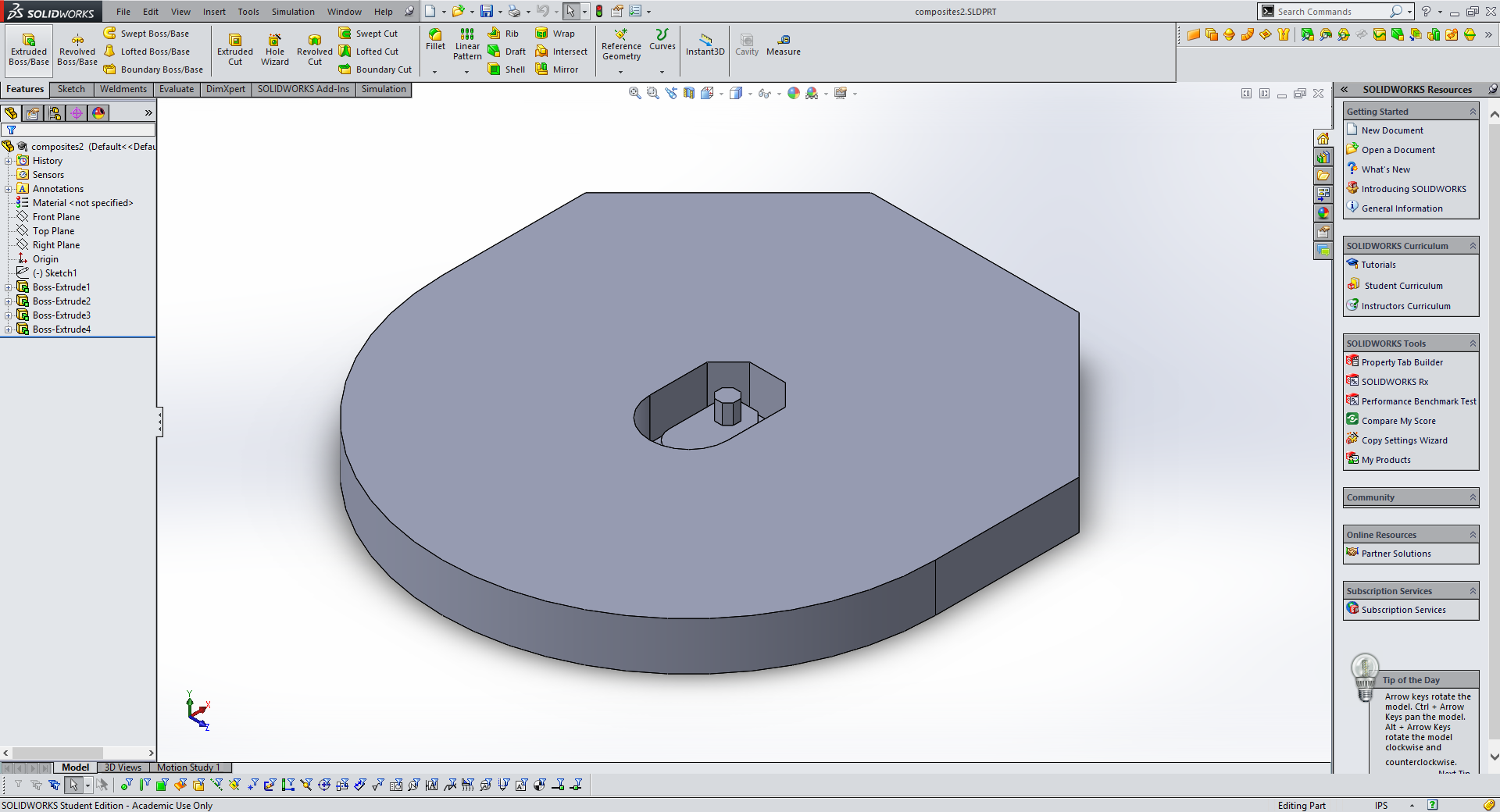
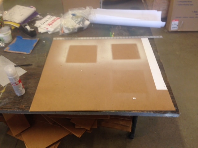
I started the process in Solidworks and created a negative mold of the shape I wanted to make with composites. I make the outside of the mold excesively large so that when I import the file into aspire, Aspire will not try to mill away all of the extra foam board around my part and will only mill out the negative indent. This saves lots of time and material. |
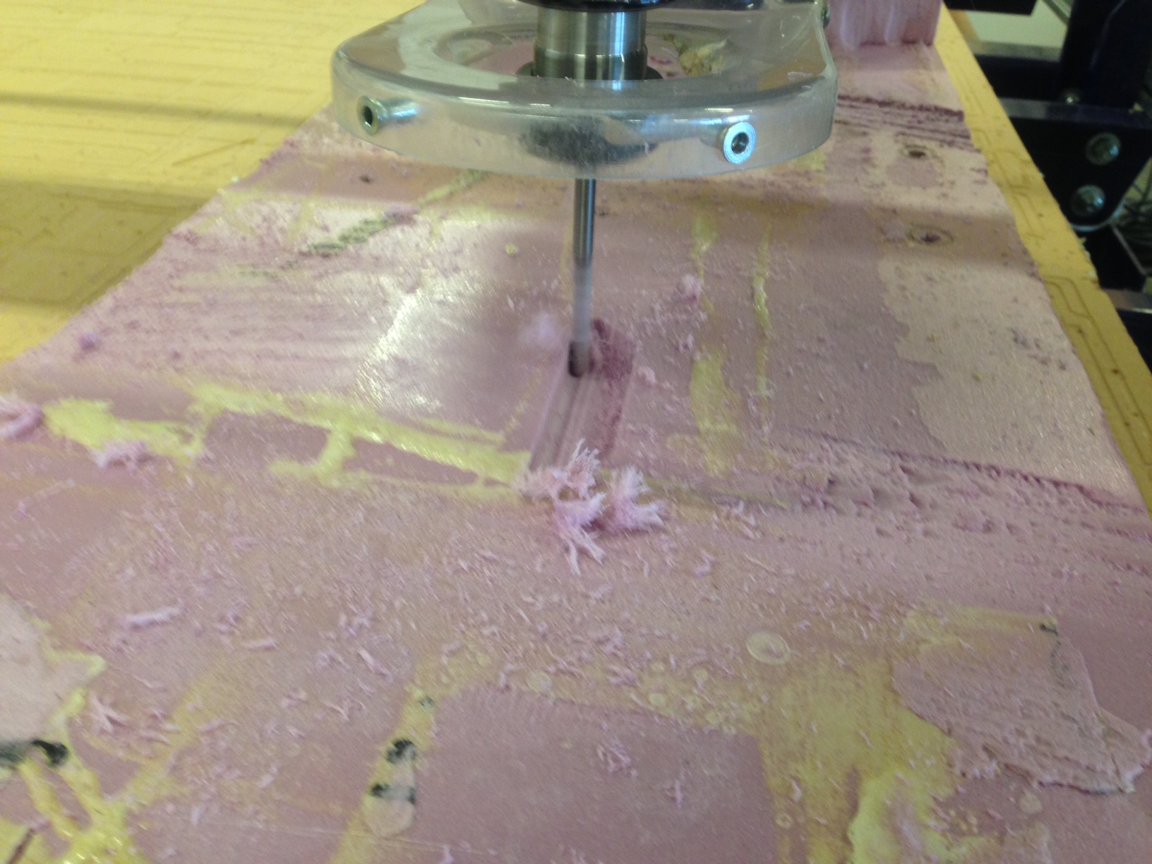
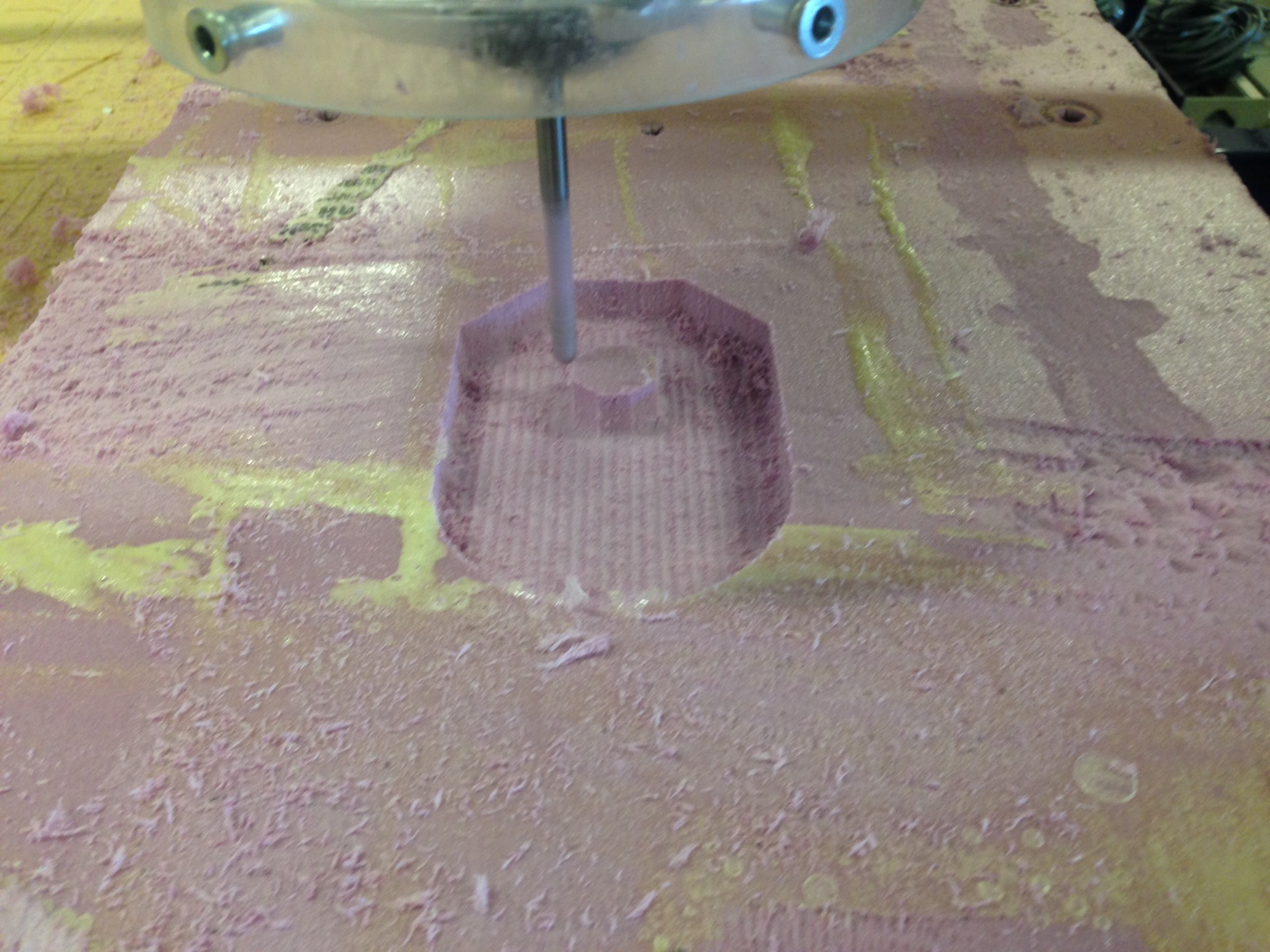
I milled my mold out of stacked foam insulation board secured to the shopbot with hot glue. I used a 1/4" endmill bit on the Shopbot with standard settings, except I change the cut speed to 120 inches per minute because foam is a very soft material. |
After cutting the mold I realized that my mold was almost exactly the depth of one layer of the 3 layer piece of foam I had milled it from. Therefor the middle raised section was weakly attached, so I used two screw to securly attach it the foam layers below. I would have used glue but glue fillets in a negative mold would appear in the final product. |
Finally, I used a hand saw to cut away the extra foam around the mold so that there would be enough room in the vacuum bag for more than one mold in the next step. |
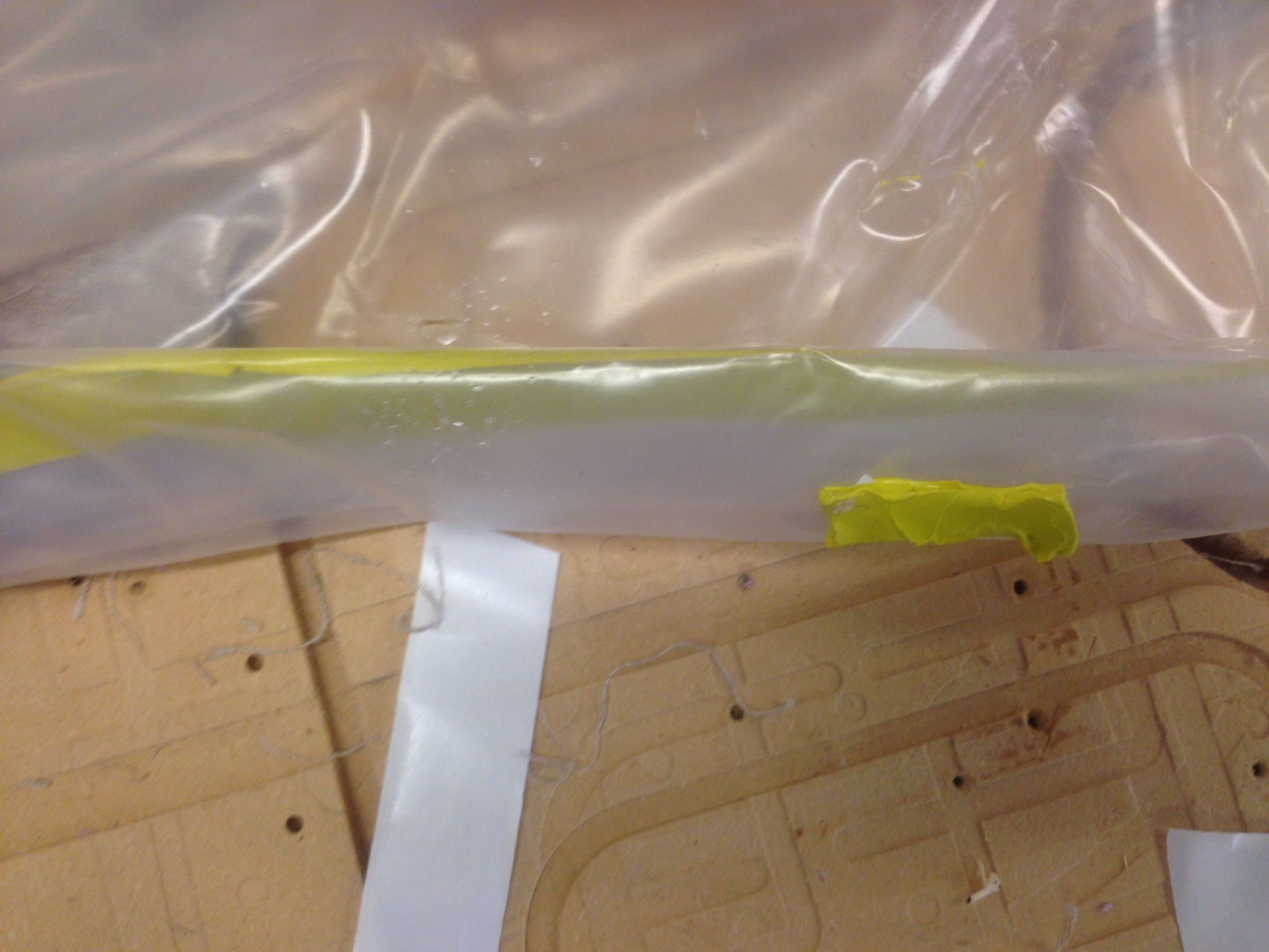
The next steps utilize vacuum bags so I decided to do some tests to determine exactly how good of a seal I could get in a vacuum bag. I found as seen above the best way is to roll the vacuum bag like you would a dry bag after applying single strip of the yellow tape seen above. Then use small tabs of tap to keep the bag roled, created a very nice, mostly air tight, seal. |
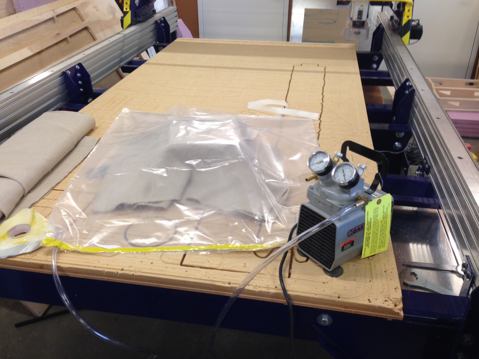
I then tested the vacuum pump in conjunction with the new seal. I also placed my mold with a dry piece of burlap over the mold to test how it would form over my part. Everything seemed to work well except that the burlap did not form over my mold very much. This was because I did not place a breather material over the burlap or any of the other layers, and because my mold is relatively small. |
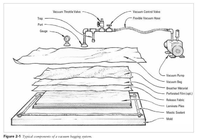
Above is a very good diagram from the SuperNode Fablab in Barcelona depicting the layers used in vacuum composites. |
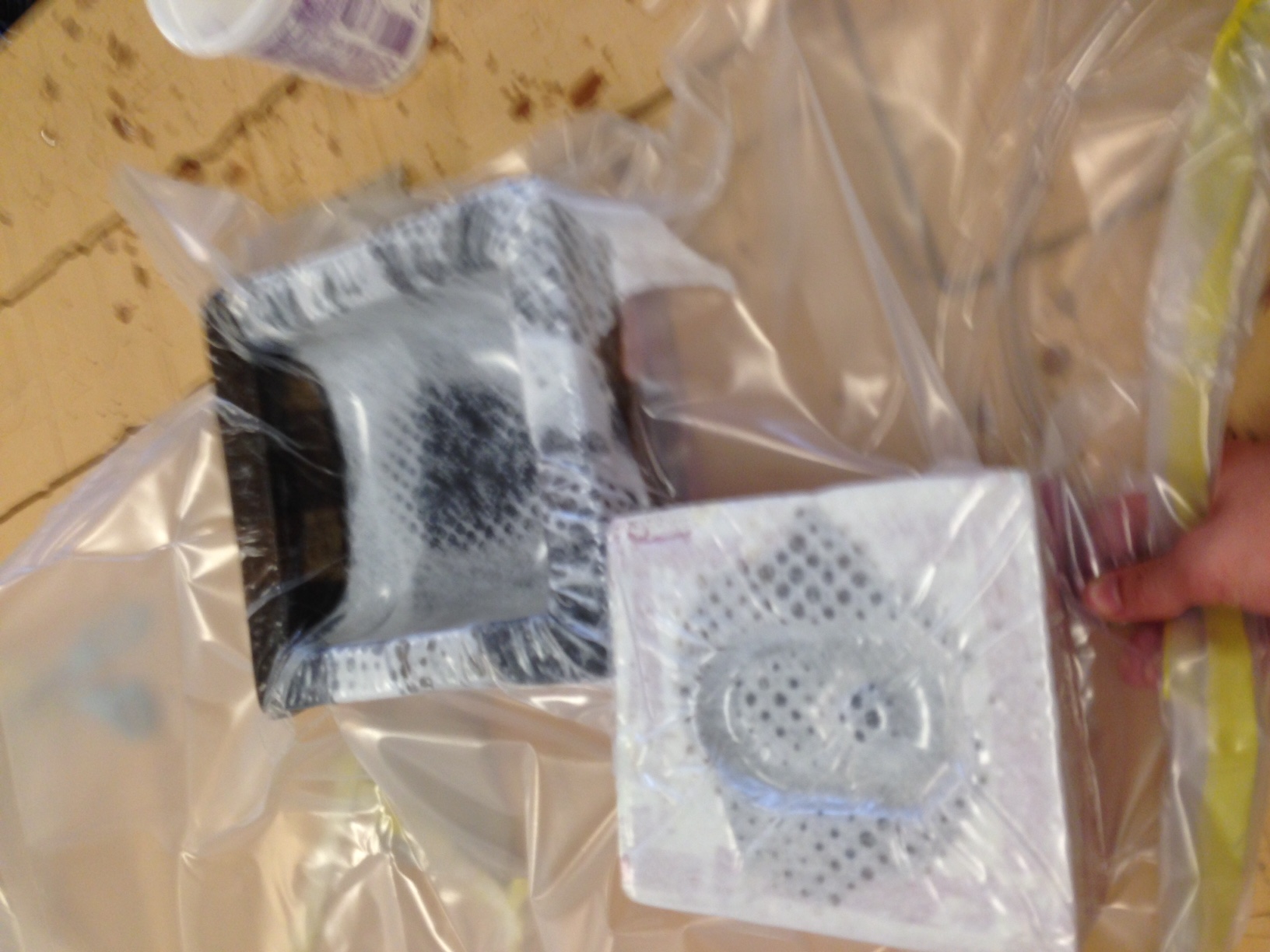
Unfortunately I do not have pictures from the next step since everyone had expoxy covered gloves on. This step was created the layer for the mold. I cut burlap strips and gathered plastic and cotton sheet for the plastic and vent layers of the mold. I then mixed 3:1 (3 resin to 1 hardener) epoxy. I sprayed the mold with mold release and then placed burlap strips inside the exterior of the mold and applied expoxy. Since my mold was so small I only got about two layers before the mold was almost full, so I stopped there, but I rolled a few addition burlap strips covered in expoxy to form rope like strings and placed then at the bottom of my mold to both strengthen those points and for the burlap layers down there outwards against the mold because they might not get the full potential of the vacuum process. All in all I felt as though I had to keep a steady pace during this process, but due to my experience working with epoxy in the past I did not feel rushed and overall this process went smoothly. Before I explain the next steps I would also like to say that due to the physical size of this mold I was not able to used plastic under the burlap and therefore did not expect the mold to survive. |
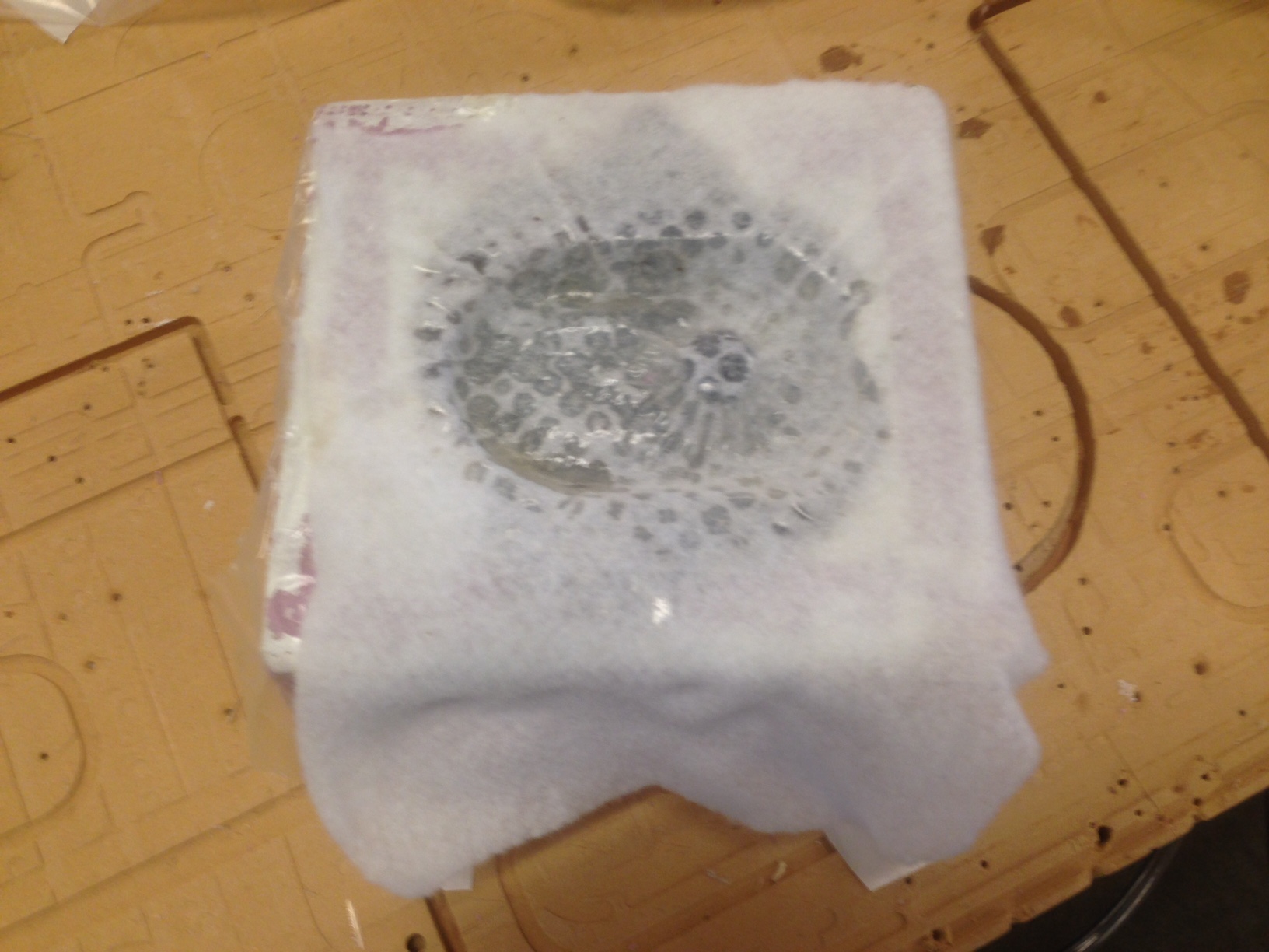
Once the epoxy had dried (when I got back to the lab the next day) I took the mold out of the vacuum back and peeled away the top plastic layers and the vent layer. Then I used a screw driver to break away the layers of foam that the mold was milled out of the expose my part. In the future I could try to find a thinner plastic to coat the inside of the mold with so I could use it again. I could also look for a gel mold release rather than a spray on which might increase the chances of the part coming out of the mold without destroying the mold. |
When I finally got the composite removed I was happily supprised with the result. It had come out much better than I ever expected it would. |
With the help of a file to remove excess foam and expoxy bumps and some a razor blade to cut away the burlap from overlay ontop of the mold the part looked pretty good. |
It even ended up fitting onto the linear actuator I designed it for. All in all I would say that this project was supprisingly successful. I really did not have high expectations for the success/usefullness of composites going into the week, but now, by the end, I have a new respect for the potential ti holds. |
For networking I decided to do the Hello bus 45 project. This project uses a bridge and one or more nodes which all communicate through the RX and TX pins on their Attiny45's. |
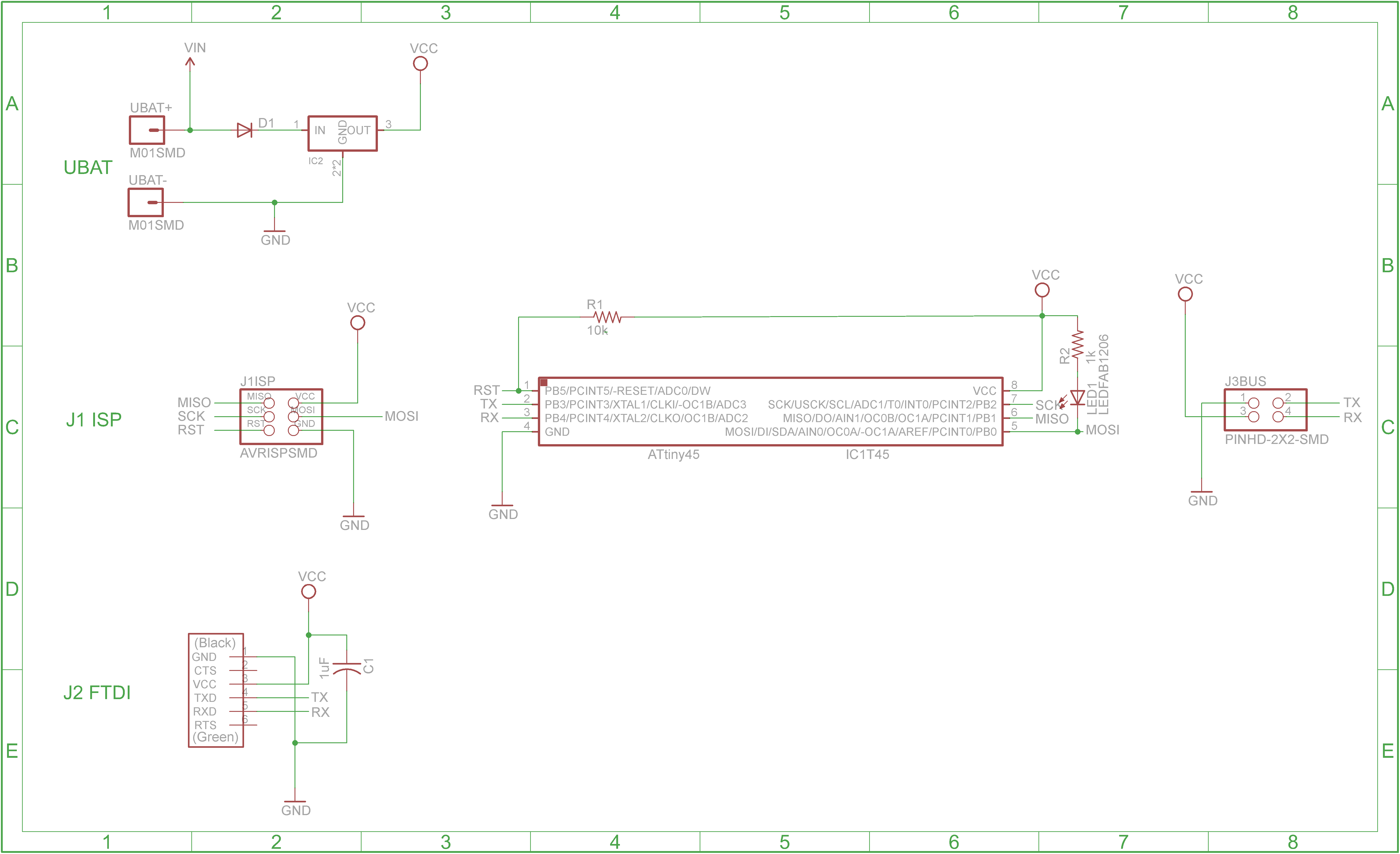
The first step was to use the bridge schematic to create one bridge module. This module gets programmed as node 0. |
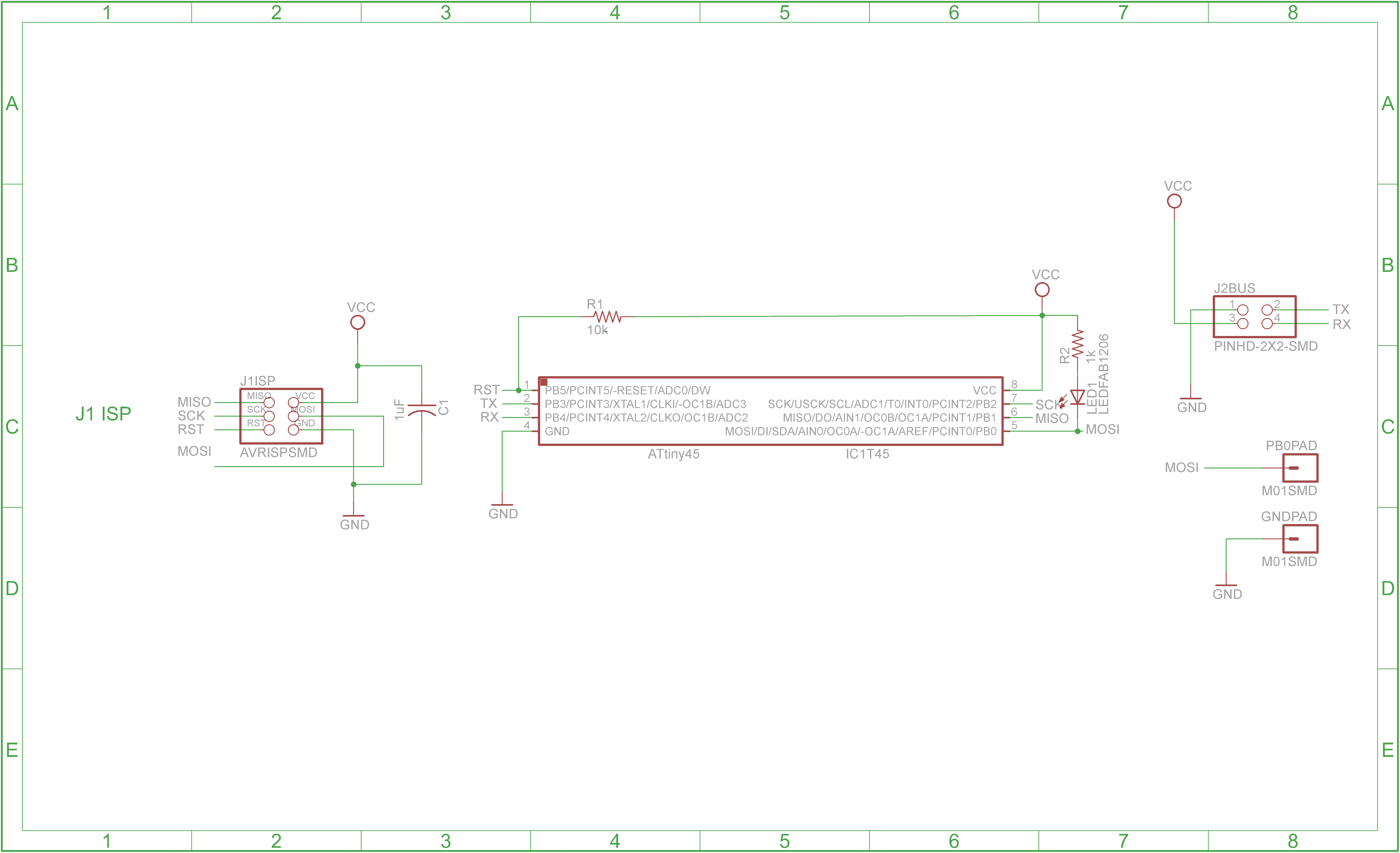
Then I created the node modules using the above schematic. These are programmed as node 1, then node 2, etc. |
Next I flashed this file to the bridge and each of the nodes using this makefile. Making sure to change the node number and re-save the file between each flash. |
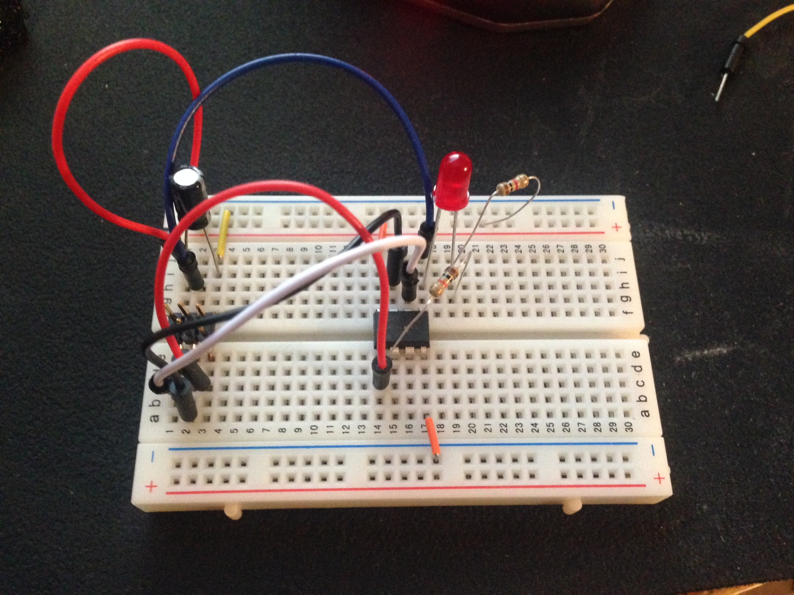
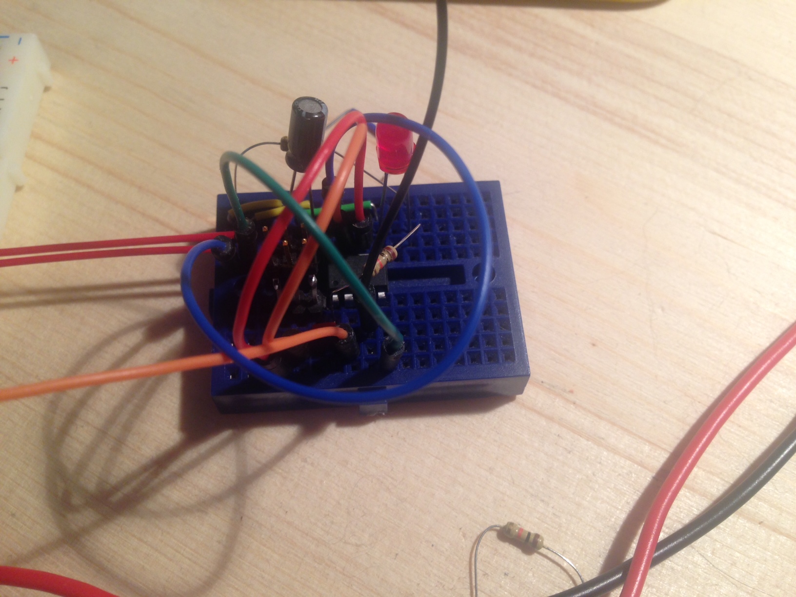
Once this was complete I used the Arduino IDE serial monitor to communicate with the system. I knew my project was finally successful when I could enter a node number for example node 1 and then all of the nodes and the bridge would light followed by just node 1 would light. |
Next I used my schematics shown earlier to mill out all of the nodes and the bridge on the mini mill. |
I cut them all on one pcb board to make it easy to keep them together and so they would be held in place when I connect them with ribbon cable. |
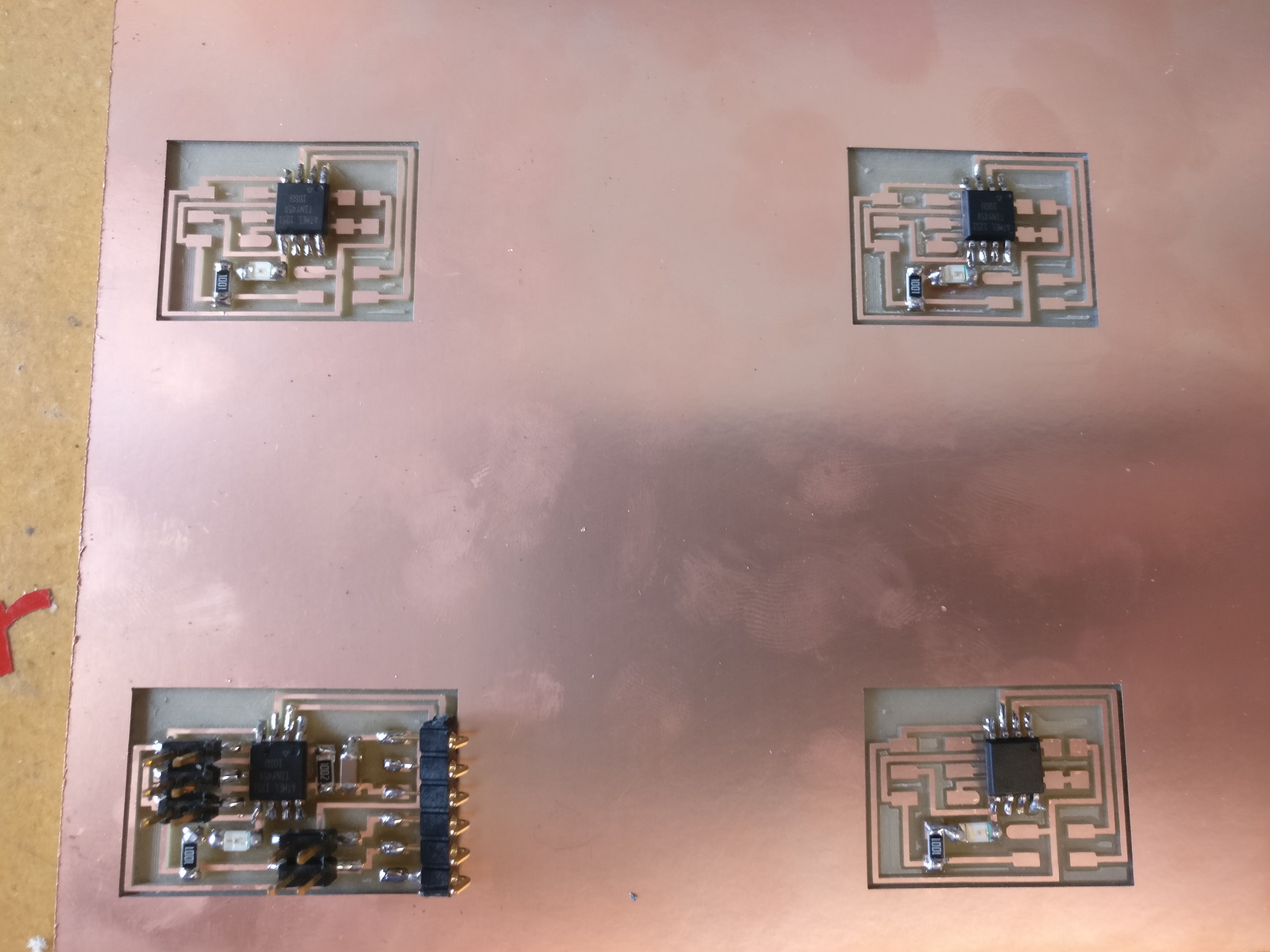
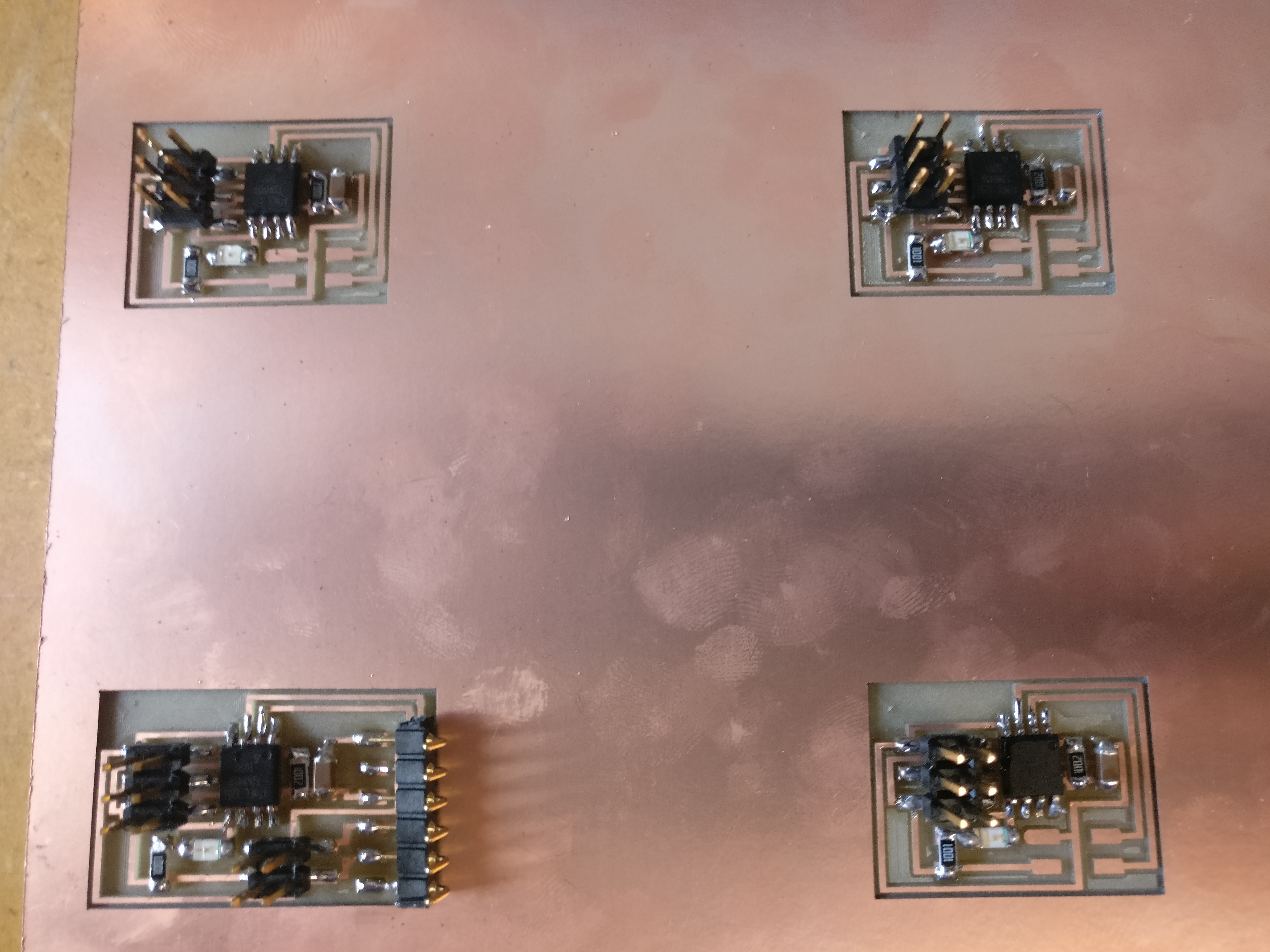
Then, as I have done with all other pcbs, I used the soldering iron and reflow station to solder the components onto their respective positions on the pcb. |
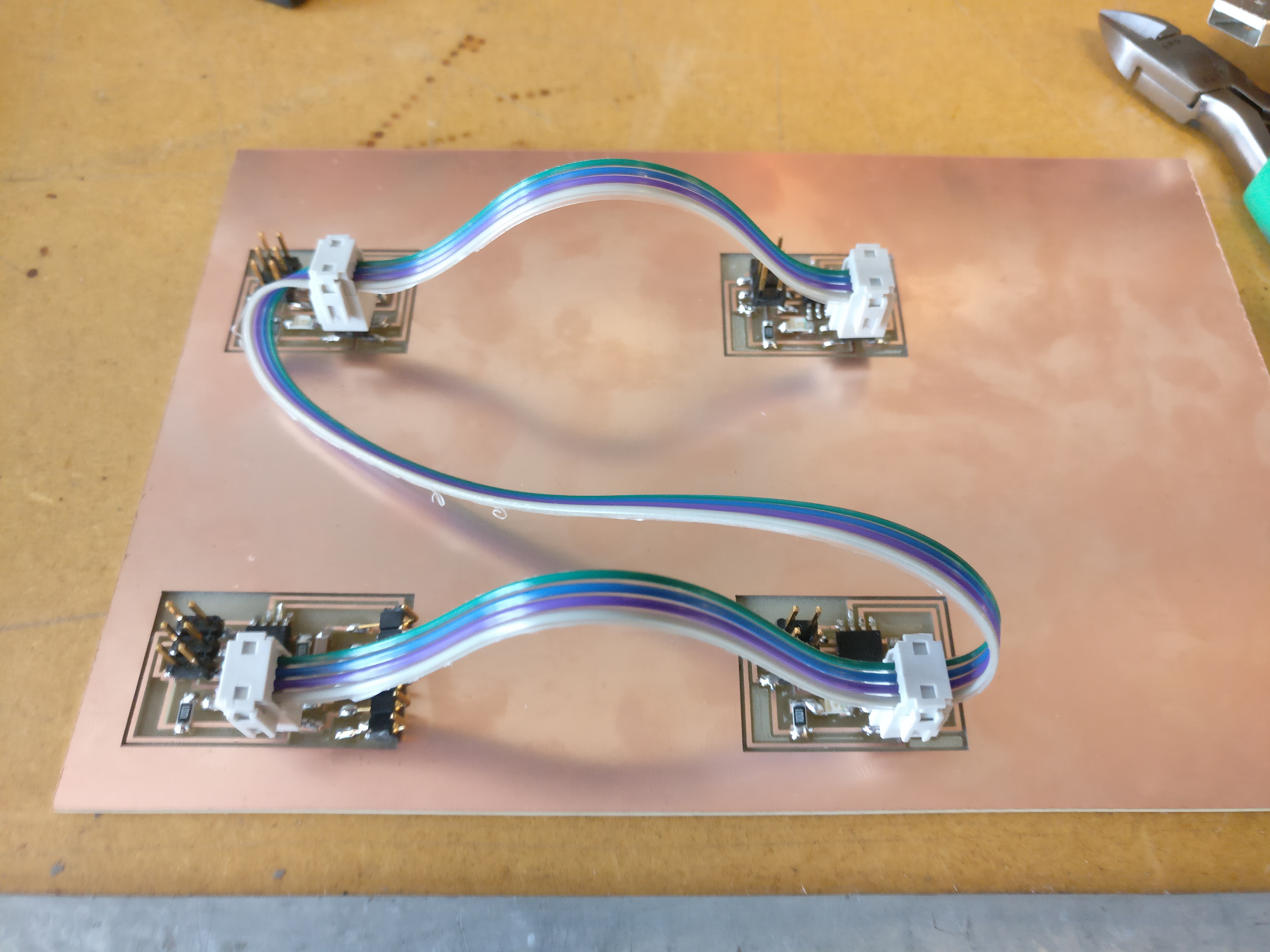
Then I used the same software steps as I used with the breadboard circuits and recreated the project on the pcb board. |
For this week I created my project using an arduino, a potentiometer, and the software interfaces Arduino and Processing. I wrote a program as available below to read values off of the potentiometer through an anolog pin and then a Processing program to take those values and display them in a visualizer as seen in the above video. |
For this week I will be discussing my final project by, outlining the project, the materials needed, and the processes involved. To see my final project worklog click here. |
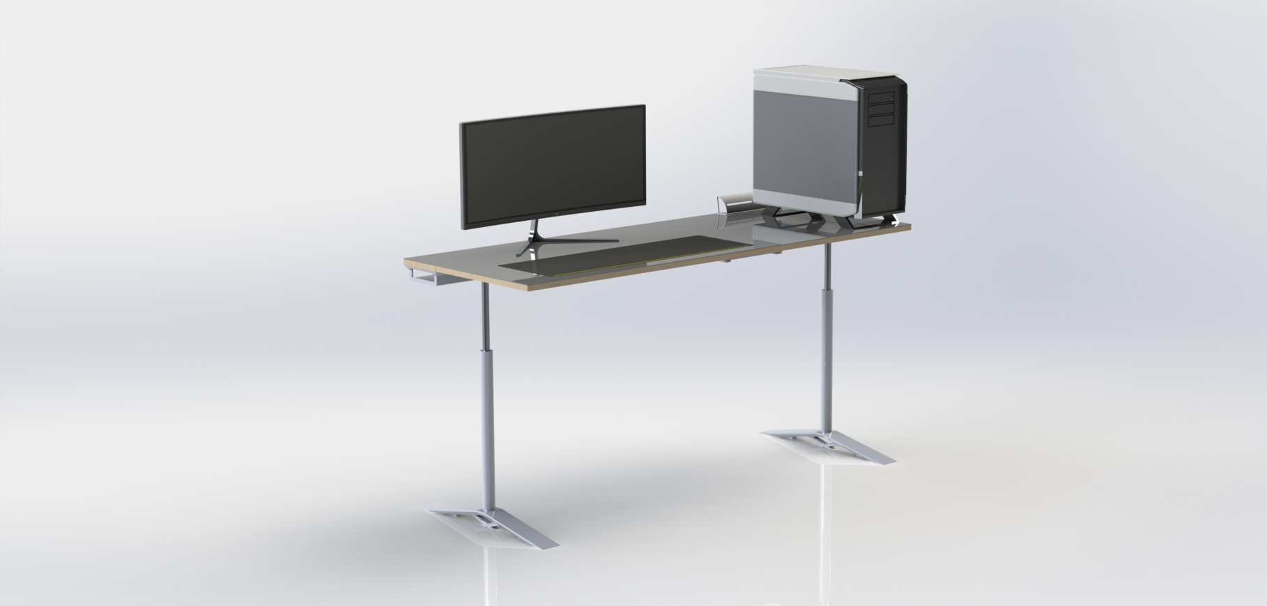
The goal of this project is to create a unique DIY piece of furniture that has an application for me and many others, similar to the project done by Wendy in her 2013 Fab Academy final project. I would like to create a desk that catters to the maker community and creates an appealing workspace for people like me. To achieve this I would like this desk to have adjustable hight so the user can sit or stand comfortably regardless of hight. I would also like to have workspace ontop of the desk, but the desk should in my opinion center around a computer with little to no clutter due to drawers or shelves of any sort. Ultimately I would like this desk to stand out in a room as a desired, modern workspace perfect for a wide range of users. |
As for the materials, I will have to order the linear actuators online, probably from Amazon, but the rest of the materials are available at local hardware stores. The total cost for all of the part will be, I hope, under $500. Here is a general BOM (Bill of Materials) for my project. |
In order to meet my goals as stated above I plan to modify my original desk design as found here. I liked the clean design of the desk as it was originally but I felt the computer case was to dominating. I am changing the design to incorperated a system below the desk on the outside of the right leg to hold a computer case below the desk surface to get it out of the way and create a larger workspace. Doing this the ethernet switch visible behind the case in the picture above becomes too prominent. I moved the switch to completely below the desk so it does not stand out from the smooth finish of the desk surface. Finally, I plan to add a small storage system to the desk. I am not yet sure whether it would be best to make a small drawer below the desk surface or compartments in the back of the desk. |
The next step in my process will be creating the physical desk from my final CAD models. In order to keep the desk strong and rigid I will either mill or caste the alluminum legs of the table. The linear motion will come from purchased linear slides. From there I will CNC the surface of the desk. The surface will consist of a layer of wood ~3/4" and a 1/4" - 1/8" heat resistant smooth plastic. Next I will 3d print the cable manegment system slightly visible on the left of the desk in the image above. I will also need to print a mounting and housing system for the electronics. As for manufacturing of the electronics themselves I plan to mill the motor controler and power distribution modules to power and control the linear actuators. I will also need to create a small circuit board that will be visible on the front of the desk to allow the user to adjust the desk to any desired hight. Finally I will purchase and add an extended mousepad and ethernet switch to the desk so it is ready for my computer. |
The software for this project should be relatively simple, but I would like to make sure that the software interface is smooth and enjoyable. I want to have the option for the user to make pre-set heights for the desk, one for sitting and one for standing that can be saved. If I have enough time I also plan to make a simple app of some sort to interface the users phone with the desk as another option for adjusting height and saving height profiles. |
Once I complete my physical project I plan to test it out right away and determine what I could do to improve it in the future. Then I will make all of the plans, software, and CAD models available so others can repeat my project. I would also like to, at some point in the future, improve the desk design and make another itteration for myself and others to enjoy. |
Click here to see my project plan, outline, and worklog. At the bottom of the page I in the link you can also find all of the dowloads for my final project. |
I have always loved the idea of open source. As a maker and tinkerer one of the things I most appreciate is when people make their work and projects easily available for others so that others can repeat their projects, make them their own, and learn in the process. Because of this I plan to make my entire project open source and available to others who wish to make a replica or change my design to fit their own tastes and needs. |
After doing some research on the internet and looking at the Creative Commons website I made the decision that my project should have a Attribution Non-commercial Share Alike License. Basically what this means is that people can copy my work as long as it is not for commercial purposes, and that whatever they create based on my project has to have the same creative commons license as the one I am using so all itterations of my project stay open source and available to others. |
By doing this I hope to keep this project open and available to others as well as encourage others to take the same path and make their work and projects available to the maker community so that everyone can build on each others work. |
Another option that I could have choosen is the Attribution 4.0 License as seen above. This license would allow for others to modify my work for their own purposes just like the other licenses, only, with this license they could manufactur it for profit and would not be required to put the same license as I used on their product. I did not choose this license because I feel that keeping my design out of commercial production will allow makers to have complete access to it and by requiring others to use the same license as I am the project will stay available to makers. |
In the future I would like this desk to be the go to desk for makers. I would like to expand it into a modular system to which makers and hobbiests can add their own personilizations and ideas. These modules or addons will hopefully be shared so that one could piece together their own unique desk from the modules created by others. This would create a unique and usefull project available to all with endless adaptablility and an community to back it. That is my dream for the future possibilities of the desk. |
This week I presented my final project through the following video and the slide below. They outline my current ideas of what my final project will come to be. I plan to create a desk that can move up and down to any desired sitting or standing height. |
This is my week 7 project, a standup desk, inspired by Wendy's 2013 Fab Academy final project that led me to create another more advanced and creative desk for my final project. The week 7 desk was a success but had a few issues. I could not sit at the desk, it was wobbly left to right, and the desk surface was rough and to flexy when pressure is applied. I plan to fix all of these issues and create the ultamate standup desk in my final project. I will eliminate the unstable legs and make them adjustable height, strengthen the desk surface, and give the desk a surface finish that will shine and be visible for miles around. Keep reading and take a look at my final project worklog and pictures through the link in the paragraph below. |
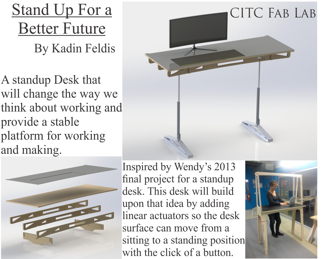
Here is a link to my final project page where I have outlined the project in more detail and will be writing my worklog. I hope the desk turns out as well as I have invisioned and I hope that others take my idea and make it even better than I will be able to with my experience and the limited time I have left to work. |