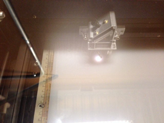
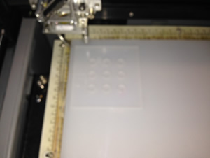
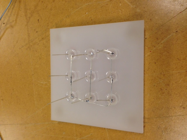
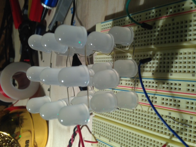
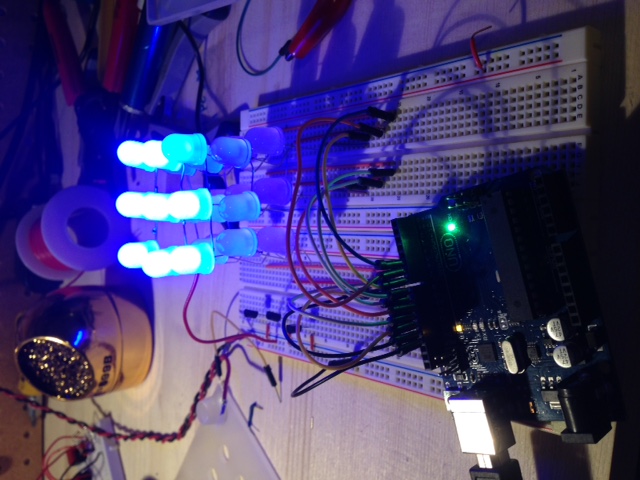
The photos above show my process for creating a mini 3x3x3 LED cube for this weeks CNC cutting. I laser cut the acrylic jig and then placed 9 LEDs in it. I then soldered the negative leads together, and repeated the process 3 times. After soldering the three layers together I plugged the cube into a breadboard. While I was soldering the cube I began to further recognize the challenge a larger cube would present. I now know that I should definetly use 5mm LEDs instead of 10mm LEDs so that I can solder the leads without running into the LEDs themselves. Also, if I want to use RGB LEDs, which I do, I is going to be very difficult to solder all of the leads and keep the cube looking clean and proffessional. |
Just a note. I went down a small rabbit hole in the next few pictures making a prototype mini LED cube, so click here if you want to skip down to the rest of my CNC work. |
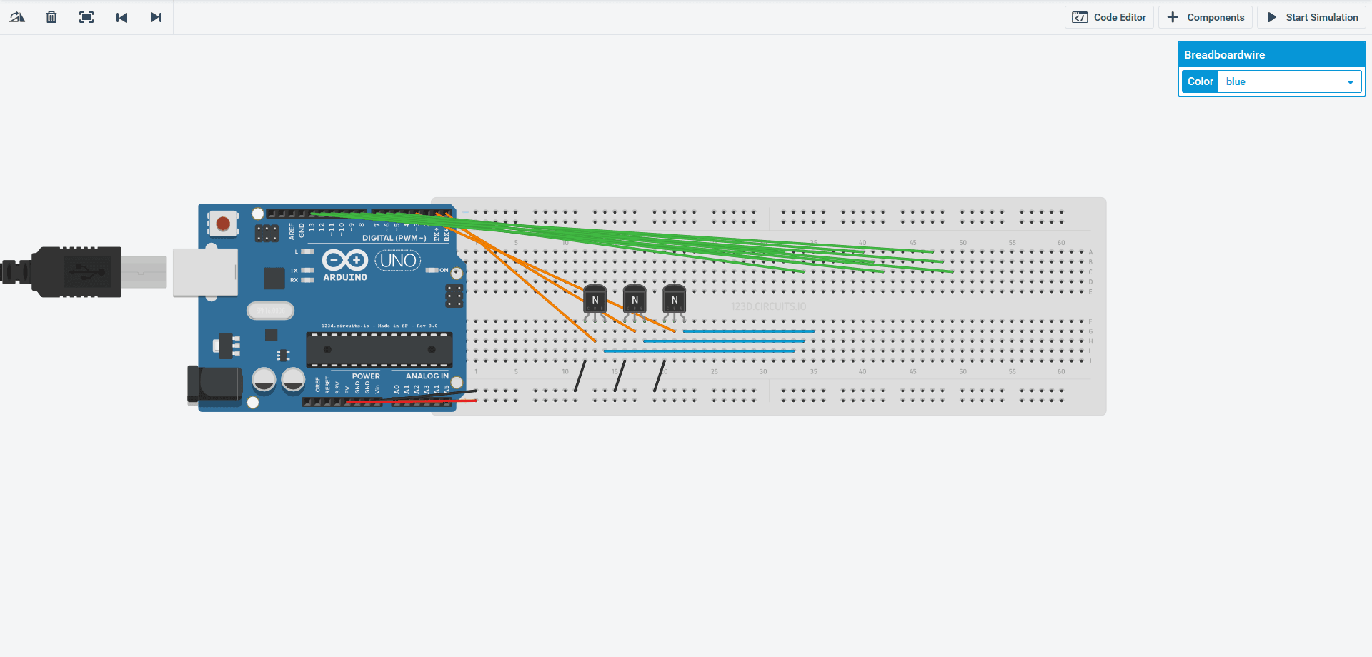
To design the circuit I used to control the cube I considerd using 123d. I played around with it and designed a simple circuit as seen above. The orange wires are outputs that control NPN transistors. Those transistors output through the blue wires which control the ground for each layer of the LED cube. The 9 green wires each control a positive column of 3 LEDs. The issue is 123d is limiting in some regards, and just to slow to be functional for large complex circuits. It is limited to 2d so it is imporssible to make a 3d looking cube, also the work area is very limited for a project the size of a cube. Another interesting note for others considering 123D, the shift registers in particular do not function well. This is because of the manufacturers recommended "max" current. Shift registers such as the 74HC595 have a very low current and voltage limit which 123d adheres to. In the real world the max current and voltage for the chips are many times higher than spec allowing them to be used in circuits such as LED cubes, but 123d will simply give you an error if you push these limits. In the end I just used a breadboard and stuck some wires in it, but for my final, more complicated LED cube I will use Eagle. |
Above is a basic animation I have been working on. It is displayed on an Arduino driven 3x3x3 single color LED cube and uses very basic software. For my final project I plan to expand to a bigger cube and hopefully RGB LEDs, because who doesn't like more color. The issue I am thinking about now is what type of ICs to use to drive the LEDs. I am thinking about either 74HC595 shift registers(maybe the ones from Adafruit because they sell a higher current rated one) or maybe Max7219(or the newer 7221). The shift registers would be easy to use and there is alot of information online on using these, but they would require more on the software side because they are only a latch and do not do any multiplexing work for you. On the other hand there are the Max7219 LED drivers, these would be good because they are LED drivers and take care of alot of the multiplexing load your microprocessor would have to otherwise handle(I will probably use an Atmega168 or 324). |
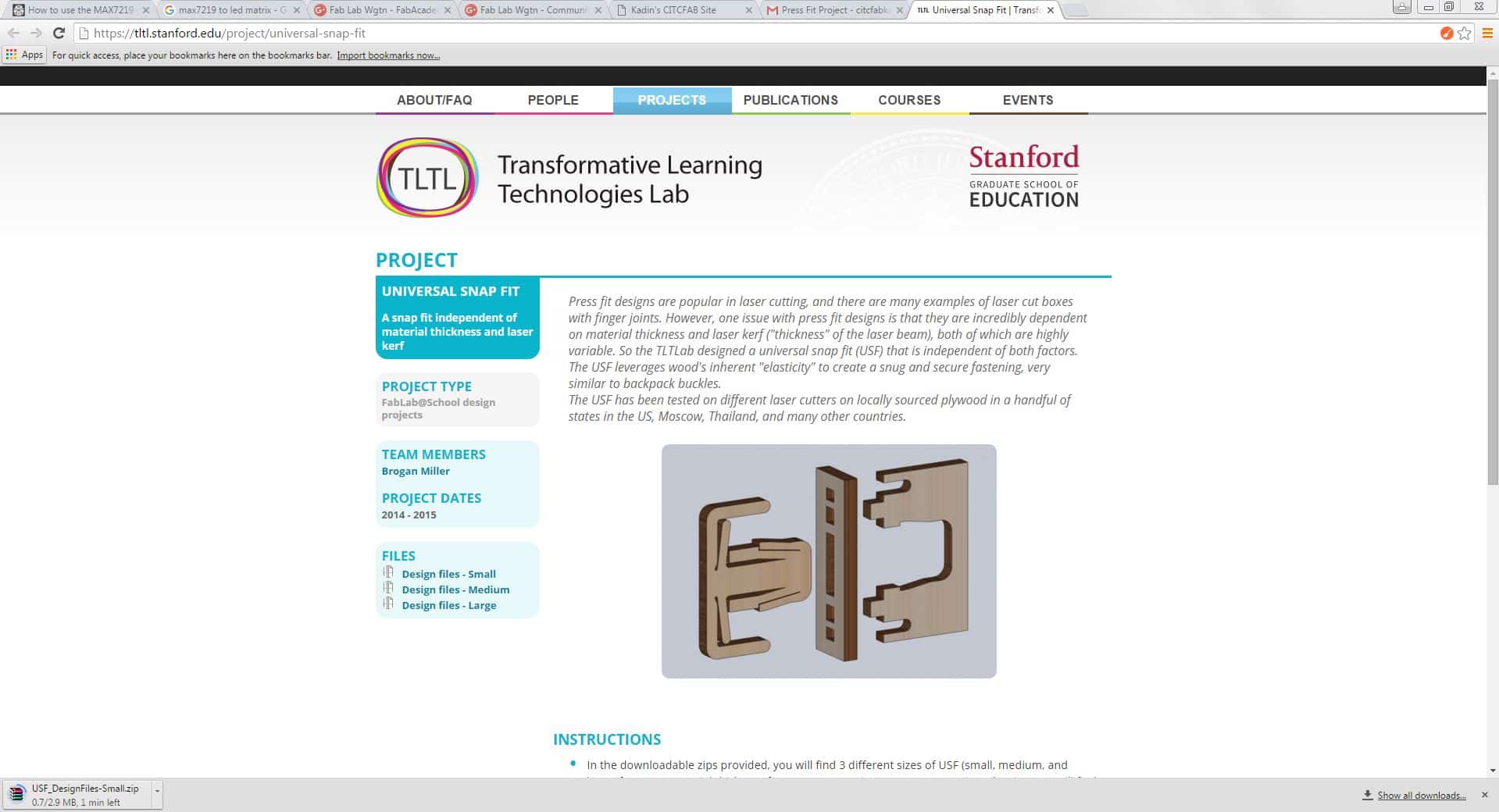
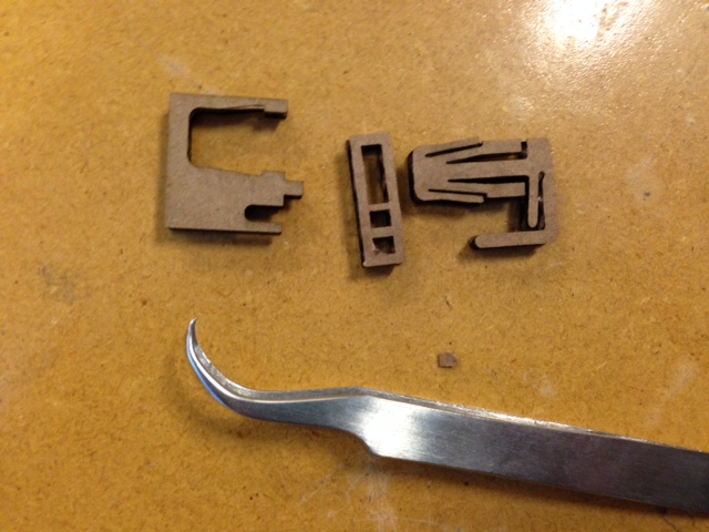
For my first press fit object I downloaded a part from TLTL(Transformative Learning Technologies Lab) Stanford. This is a simple part that would allow me to get familiar with the process of making and assembling press fit structures so I could make my own. |
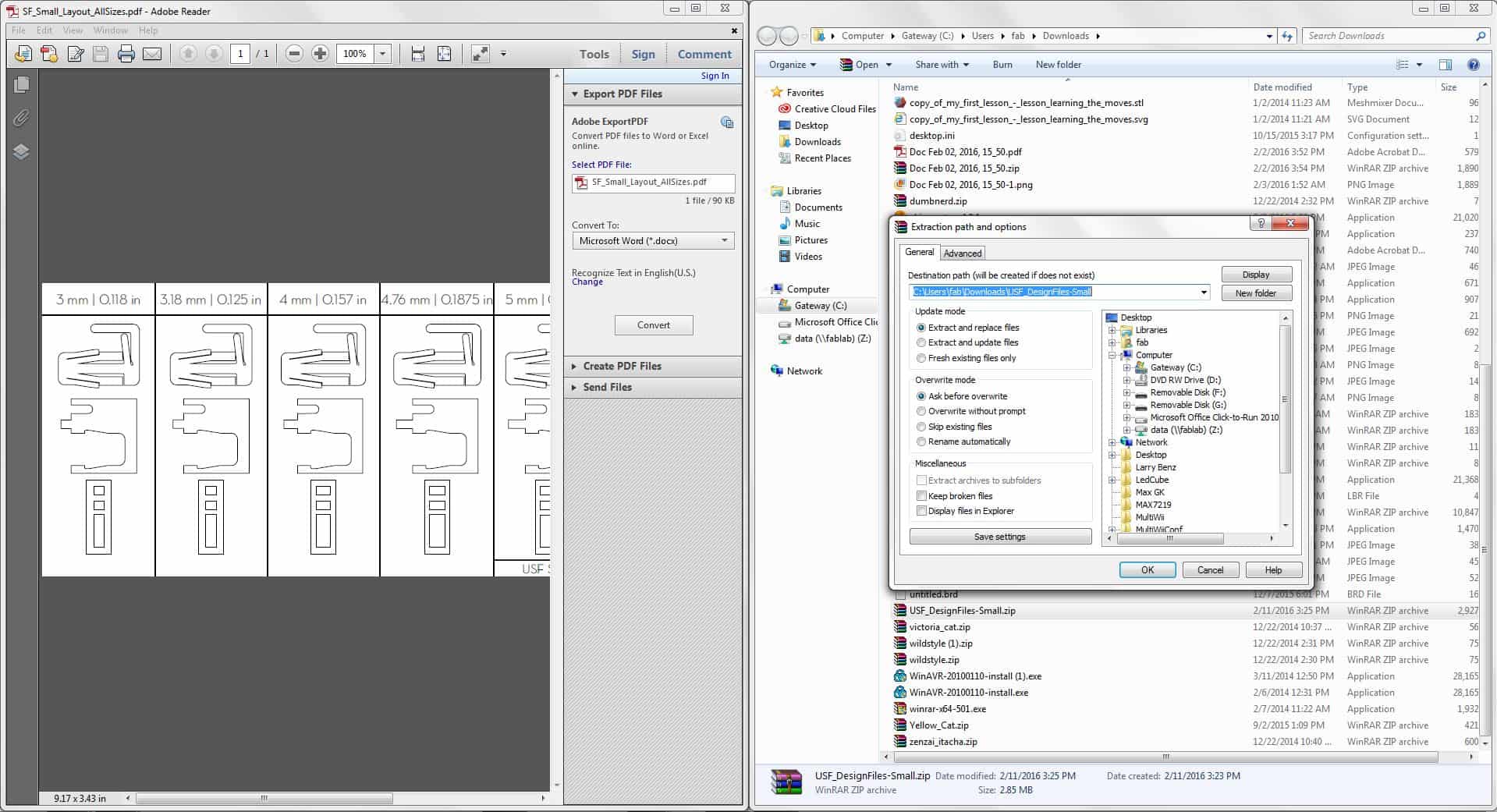
After downloading the files from the TLTL Stanford page I unziped them and opened the PDF file. After opening the PDF file I found that there were multiple sizes for different material thickness, so I needed to select one. |
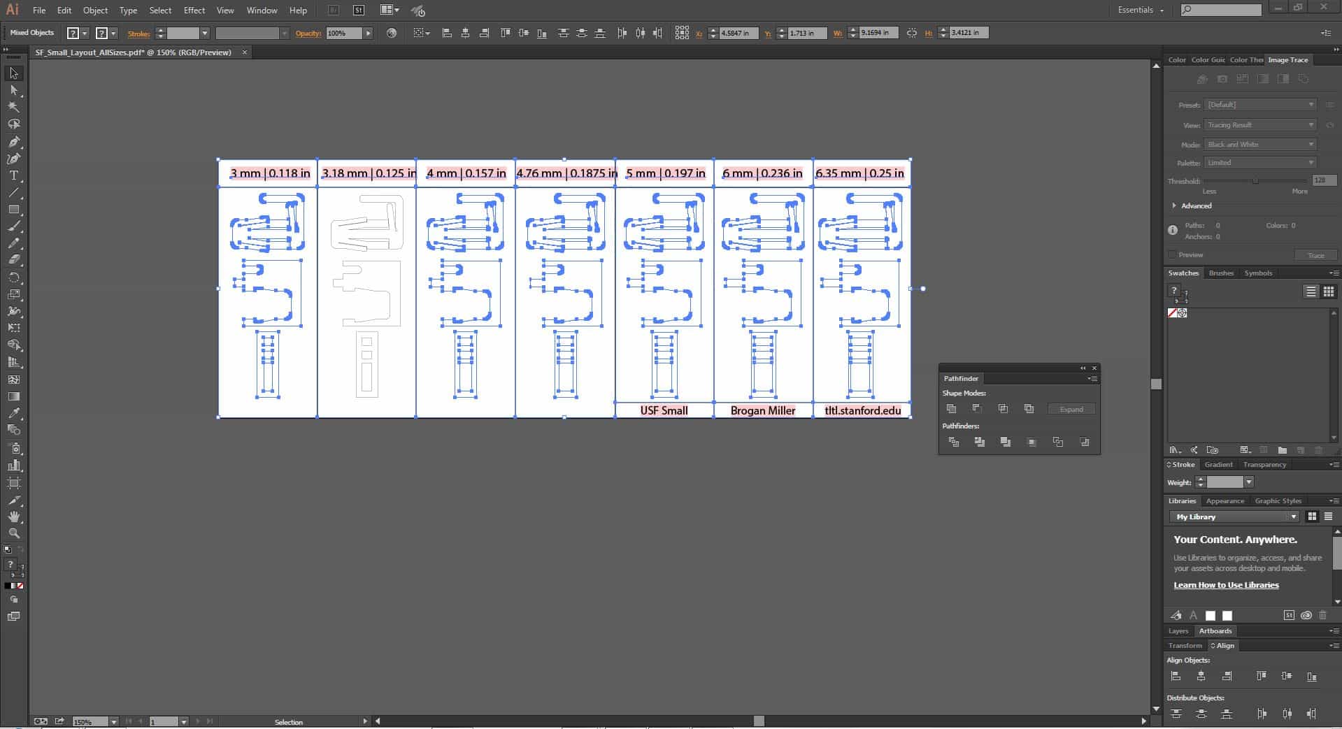
I opened the PDF and used my new skills from last week to delete all of the other designs that I did not want. |
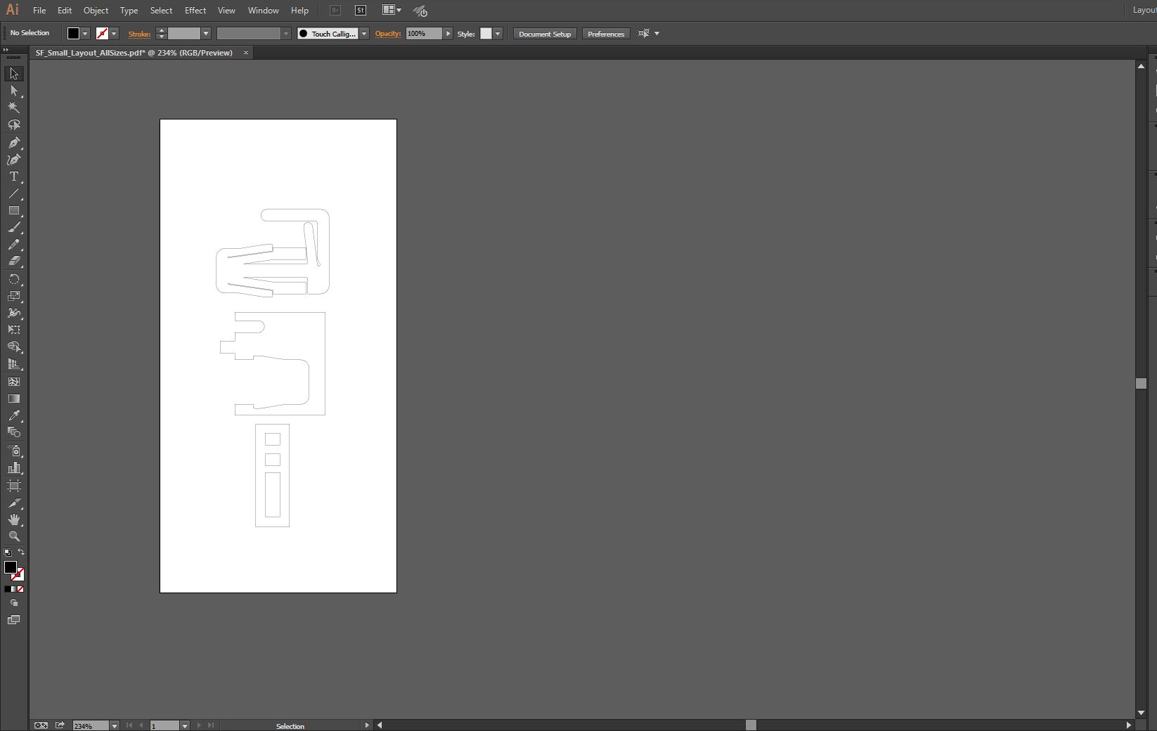
After deleting the other designs I adjusted the artboard(workspace) to fit the single design. |

Next I adjusted the line thickness/stroke from the default 0.072pt to 0.001pt so that the laser could read the lines. |
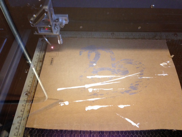
Using a scrap piece of cardboard I cut out the parts downloaded from TLTL and adjusted on Adobe Illustrator. |
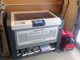
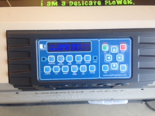
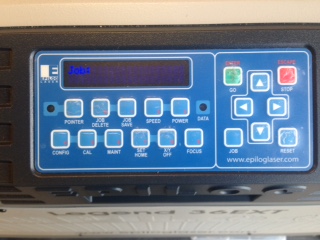
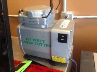
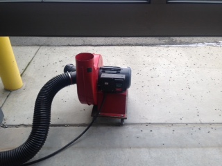
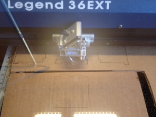
Setting up the laser cutter is pretty straight forward. On the left side of the laser cutter there is an on off switch. After you turn that on the laser will initialize and a menu will appear. Before selecting your file the small pump, with green letters in the picture above, must be turned on. Then the blower unit is placed outside and turned on to vent the fumes. Finally select the job and the cutting will start. |
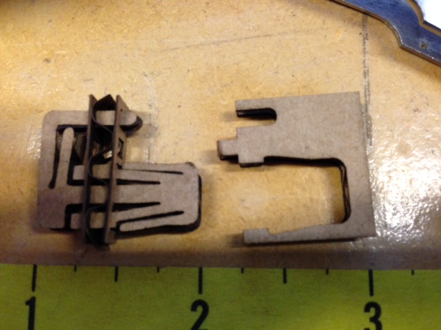
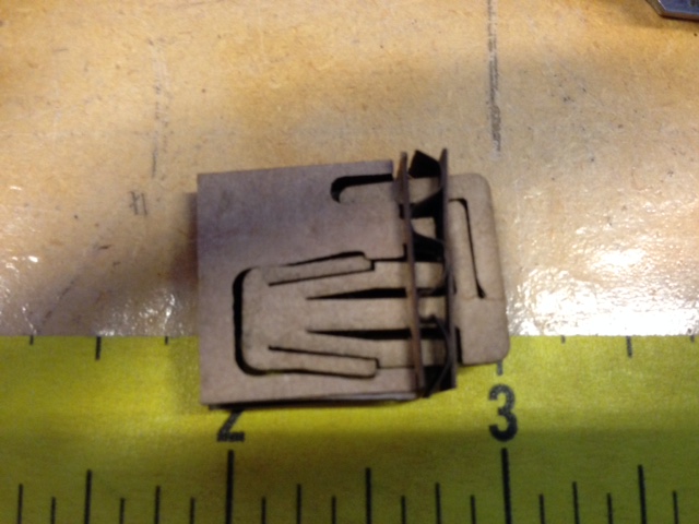
After cutting out the cardboard pieces, I used tweezers to remove a few little pieces of cardboard still filling some of the slots. Then I slid the parts together. This took alittle work since I was using an imperfect scrap of cardboard but in the end I got them together and made by 1" by 1" press fit cardboard structure. |
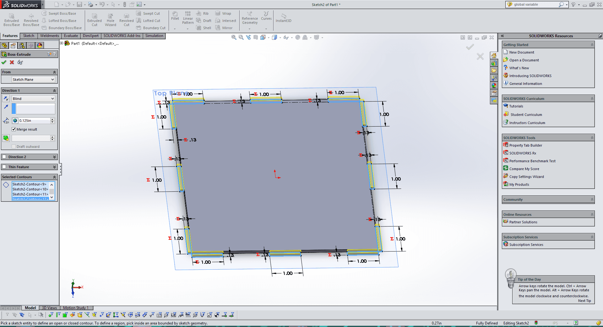
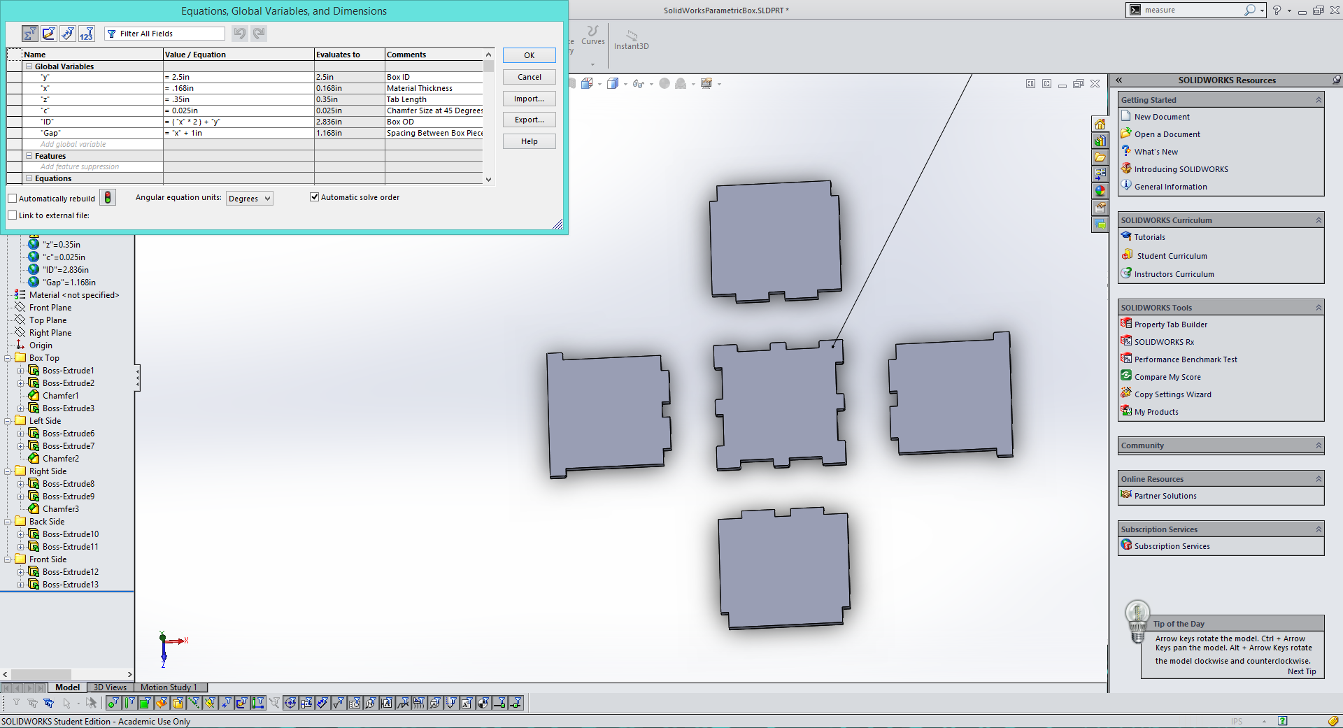
For my next project I decided to create a parametric box design in Solidworks. I wanted to have a file that I could edit for any size material to create any size of box. Here is a link for the Solidworks file for anyone who would like my SolidWorks Parametric Box file. |
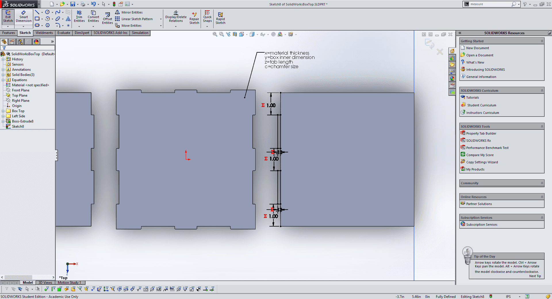
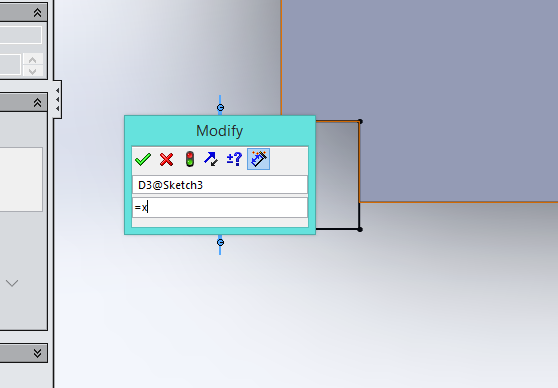
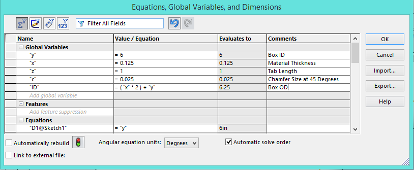
When designing the box I added a number of variables that can be changed to define the box. These global variables are present in all of the sketches that make up the file. Y is the inner dimension of you box. X is the material thickness. Z is the tab length. C is the chamfer size at 45 degrees and just to mix things up ID is the OD or outer dimension of the box. All of these can be modified in the downloadable file in the link above by going to Tools>Edit Varibales. |
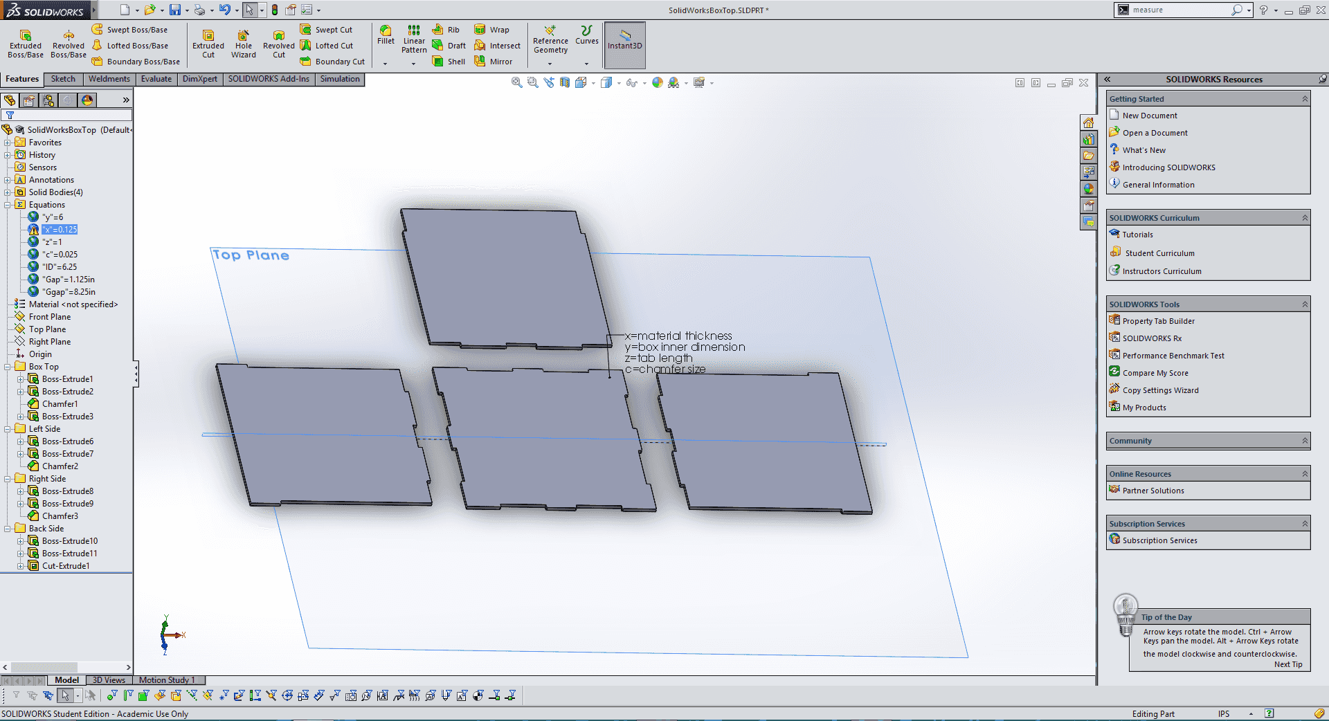
The box has 4 sides, so it has not bottom this is because I am going to use this file to create boxes for my LED cube project that will have its own 3d printed baseplate. I plan to add another file with a completed box for anyone who wants to use it. Once I was done with the box I changed the variables for my cardboard thickness and a 2.5" length/height. |
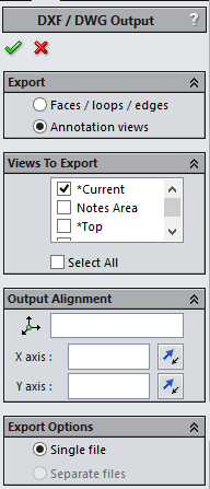
Next, I saved the Solidworks file with the variables set for my cardboard as a .DXF, this can be done by going to File>Save As>.dxf. Solidworks will then give you a menu as seen above, simply select "Top" and then hit the check mark to save the file. |
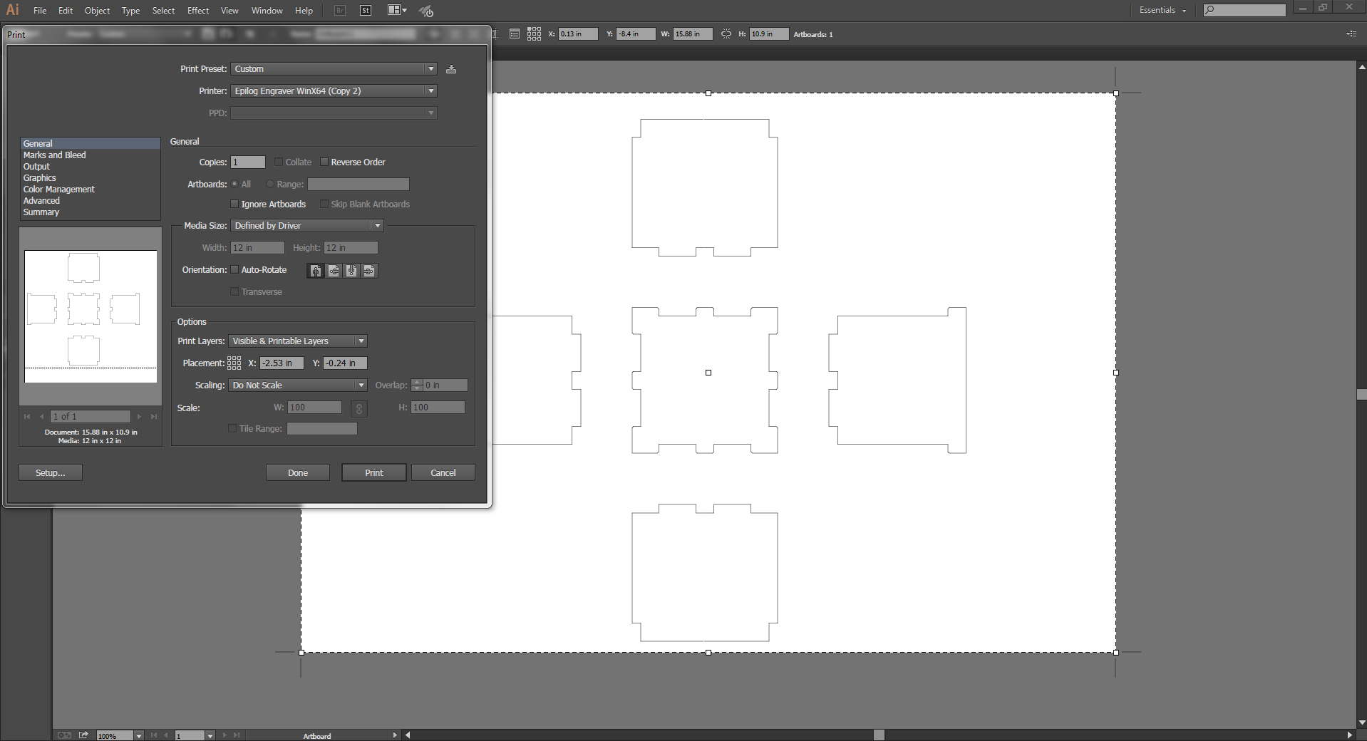
Finally, I opened the .DXF file I exported from SolidWorks in Adobe Illustrator so cut it. I changed the stroke/line thickness to 0.001pt and then hit print. |
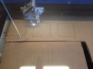
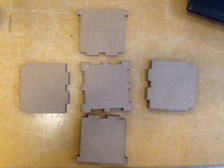
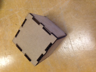
After the Epilog Laser Cutter cut out the pieces I pressed them together and my first press fit box of the class was complete. The only tricky part about cutting is when you are using scrap material, as I was, sometimes you have to spend a little extra time making sure your material lines up. |
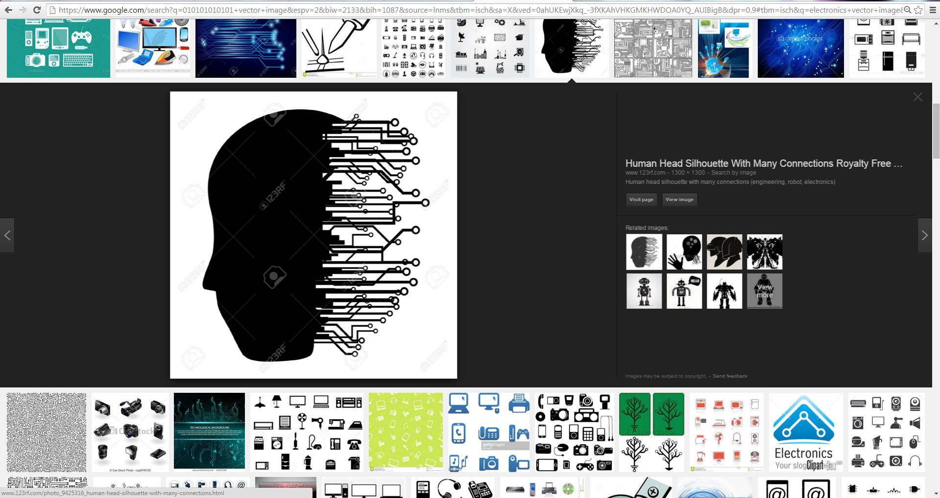
For my vinyl cutting project I found a vector image of a human head with some cool electrical connections attached. |
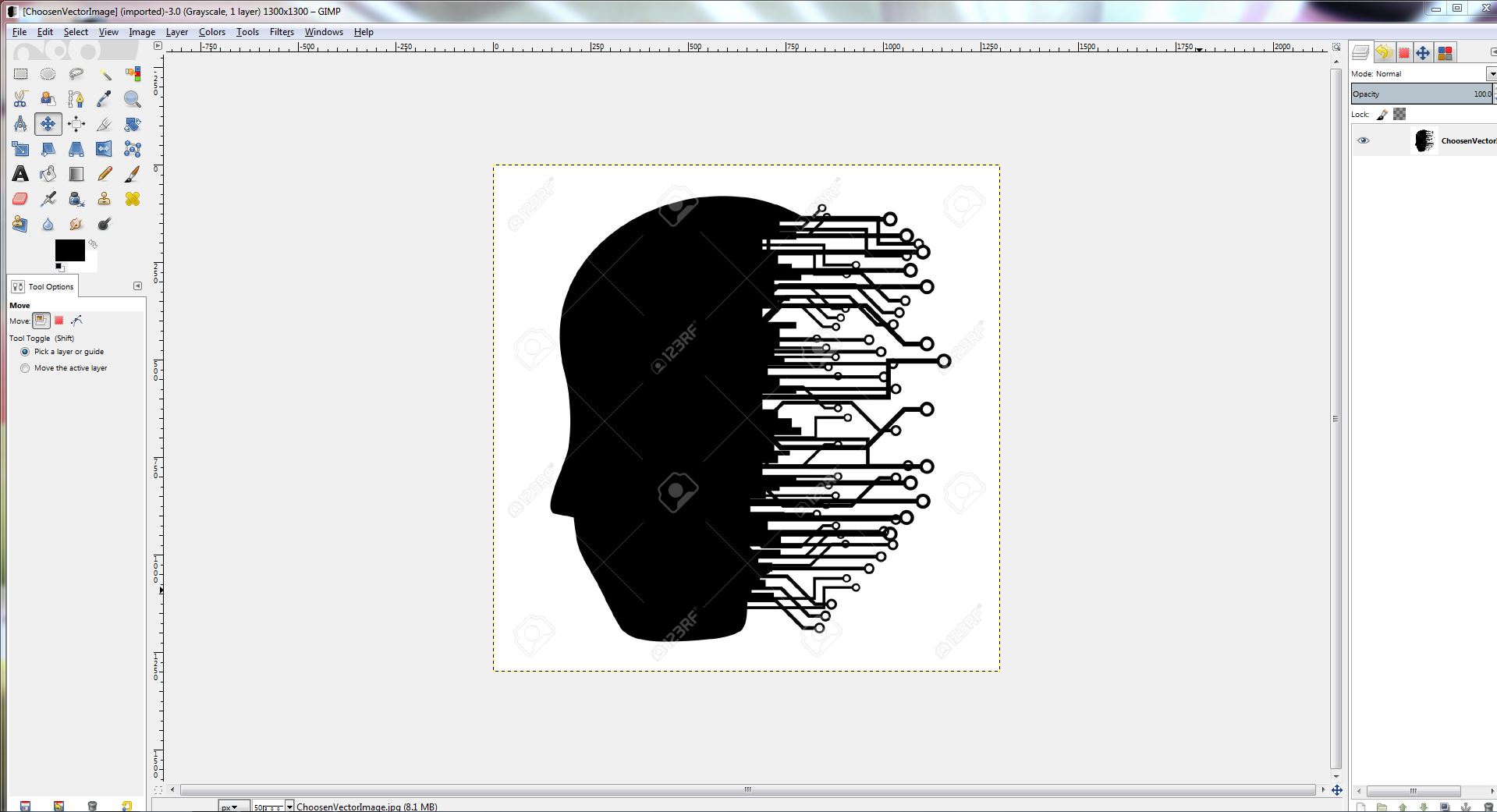
After downloading my vector image, I opened it in Gimp to get ride of the watermark. After that I opened the file in AdobeIllustrator and tracked the image, making sure to change the stroke to 0.001pt. |
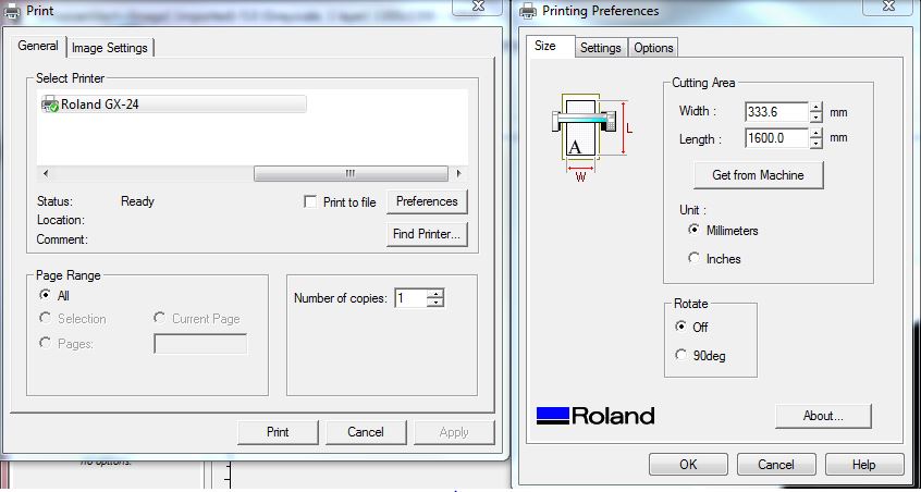
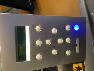
Finaly I hit print in Adobe, and adjusted the prefrences to pull the cut area size from the machine. Before this can be done the vinyl cutter must be turned on, and either Sheet, Role, or Edge selected. The machine will then measure your piece of vinyl. |
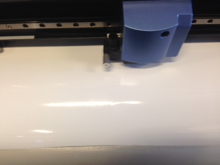
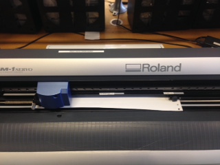
The vinyl cutter then cut out my downloaded design. |
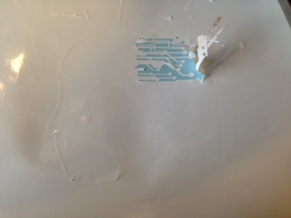
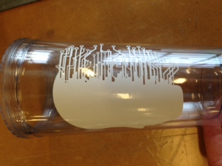
Once my (downloaded)design was cut I began the laborious process of peeling out my design. The process is made much easier by using a pair of tweezers, or simply don't select a design with lots of tiny details. Finaly once I removed my design I stuck it onto a plastic cup that I wanted to sandblast. One note, I decided to peel out my design and use it as a sticker in the sandblasting process instead of using the stencil. This is totally up to whoever is doing it but just keep in mind which area you want textured by the sandblasting. |
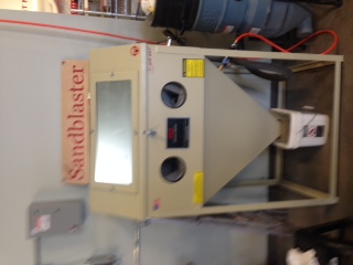
Since I had just finished vinyl cutting it seemed that sandblasting was the next logical thing to do. |
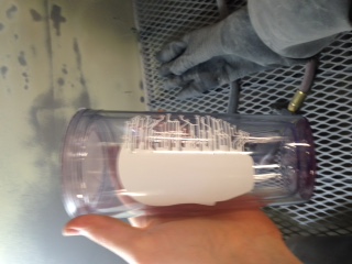
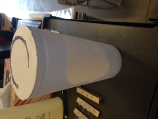
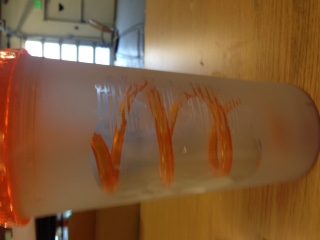
The sandblasting process is relatively simple. I took my plastic cup with the vinyl cut design and put it in the sandblaster. Making sure to close the lid tightly I turned on the light, filter, and air compressor. After that its just a few minutes of work with the sand gun making sure to texture all of the exposed plastic evently. After that I peeled of the vinyl and washing off the excess sand I had a nice new, custom cup. |