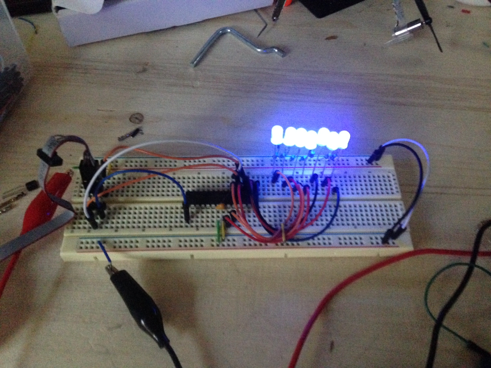
For this week, output devices I decided to make a POV(persistance of vision) toy. The idea is a row of LED lights that is blinking very fast and as you shake the lights or move your eyes back and forth past the lights without focusing on them you can make them appear solid or disappear all together. During a project like this I would always recommend checking out the microcontroller datasheet for the microcontroller you are using. The datasheet will give you usefull information such as the microcontrollers clock speed, memory capacity, and pinout. |
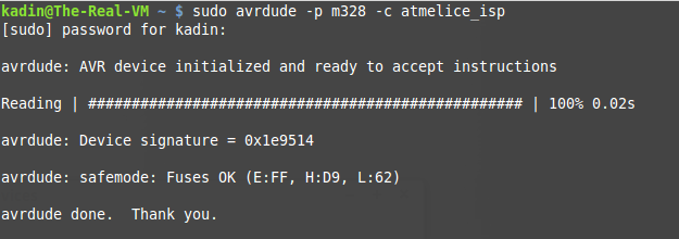
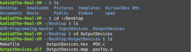
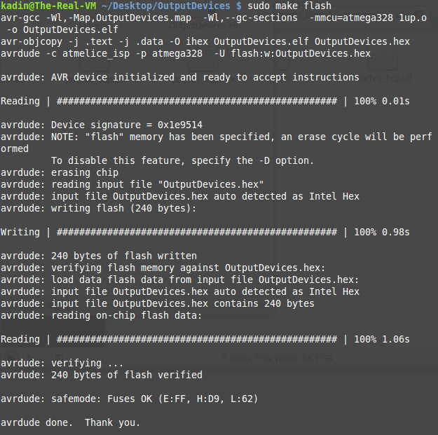
As before, to program the processor in Linux simply, check your programmer is communicating with the chip, navigate to the location of your software and make file, and finally flash the software to the processor. |
The final product is a very cool toy that can consume you for hours as you experiment with different delays for the blinking of the lights. It is hard to really see on camera but I took a video anyway. You can get the code here. And the makefile here. |
Once I completed the project I dug out my input devices pcb and again, like in input devices, recreated the same project using a milled pcb board. |
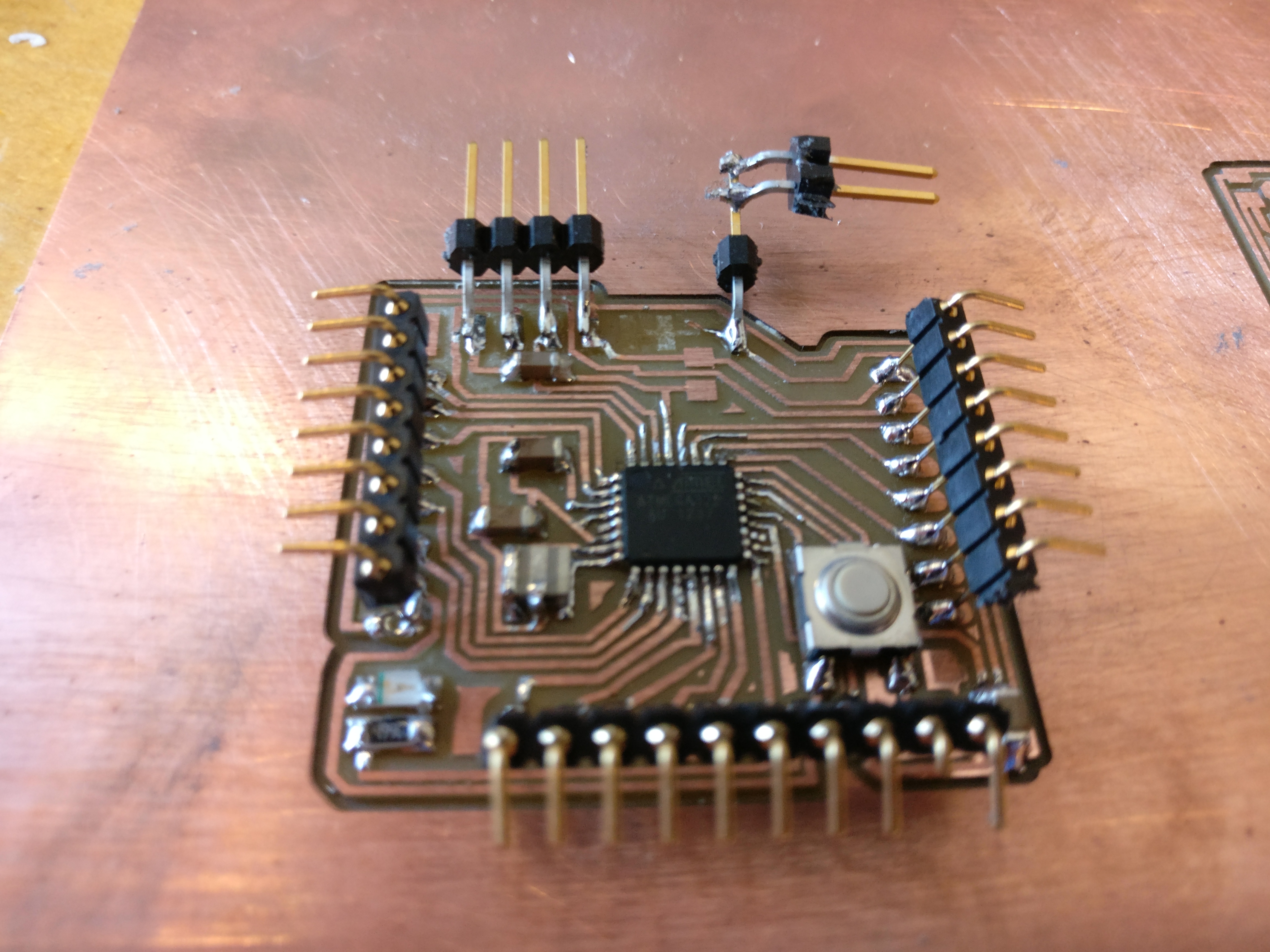
For my second output week project I used a networking board due to special circumstances. I was overseas at the time of doing this project and the power pin on my Attiny44a based development board broke off. My only alternative was to hack a networking board and solder on some LED lights for my output week board. |
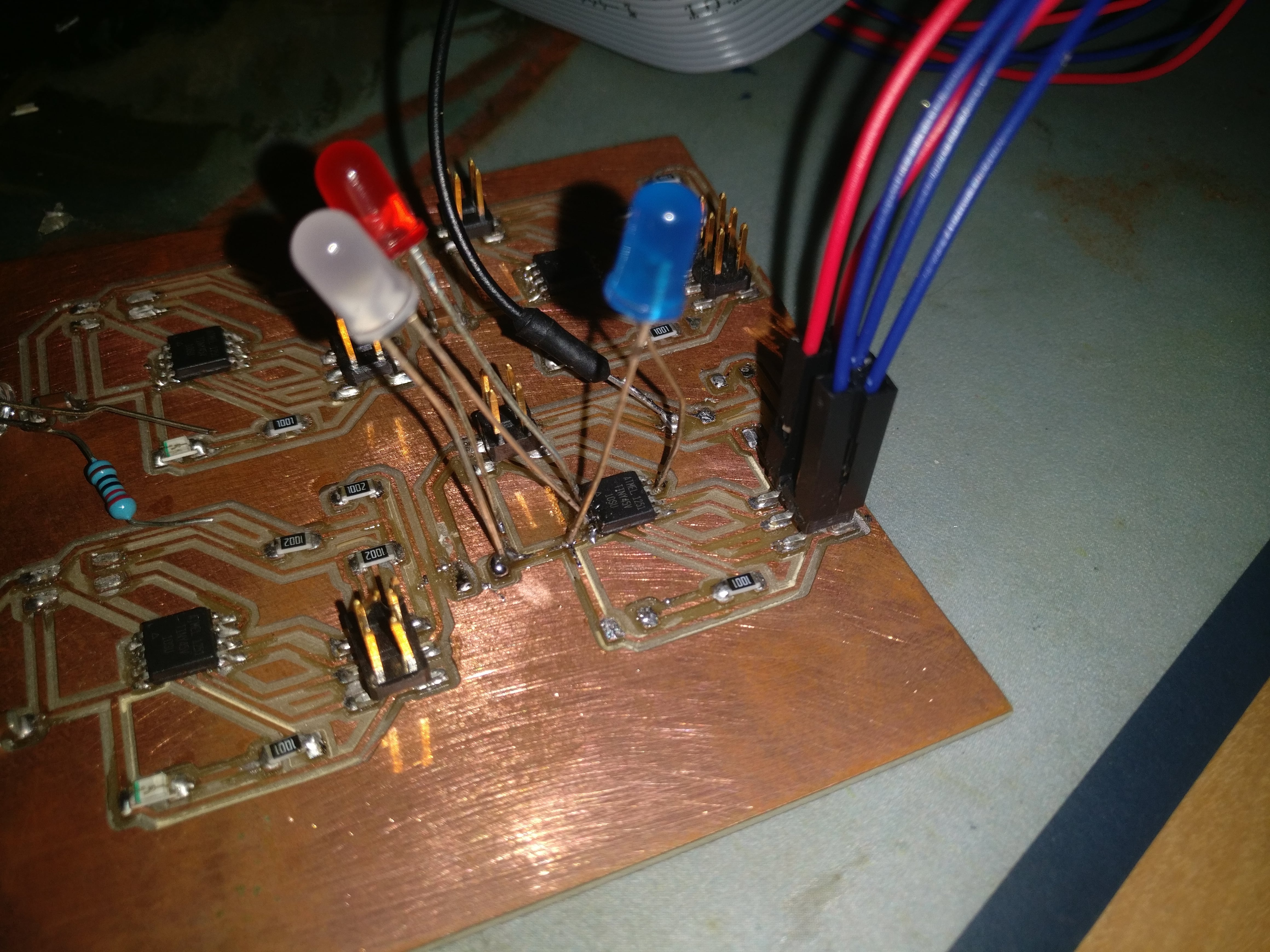
As you can see above I decided to go for a patriotic theme of red, white and blue. |
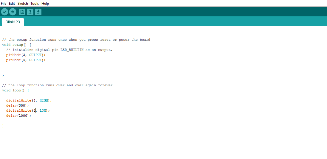
I programmed the board through Arduino IDE using the same method found here in my week 10 input devices project two. I used a USBasp programmer. |
Once I got it working the board could be made to flash in any sequence of red white or blue for varying durations. |
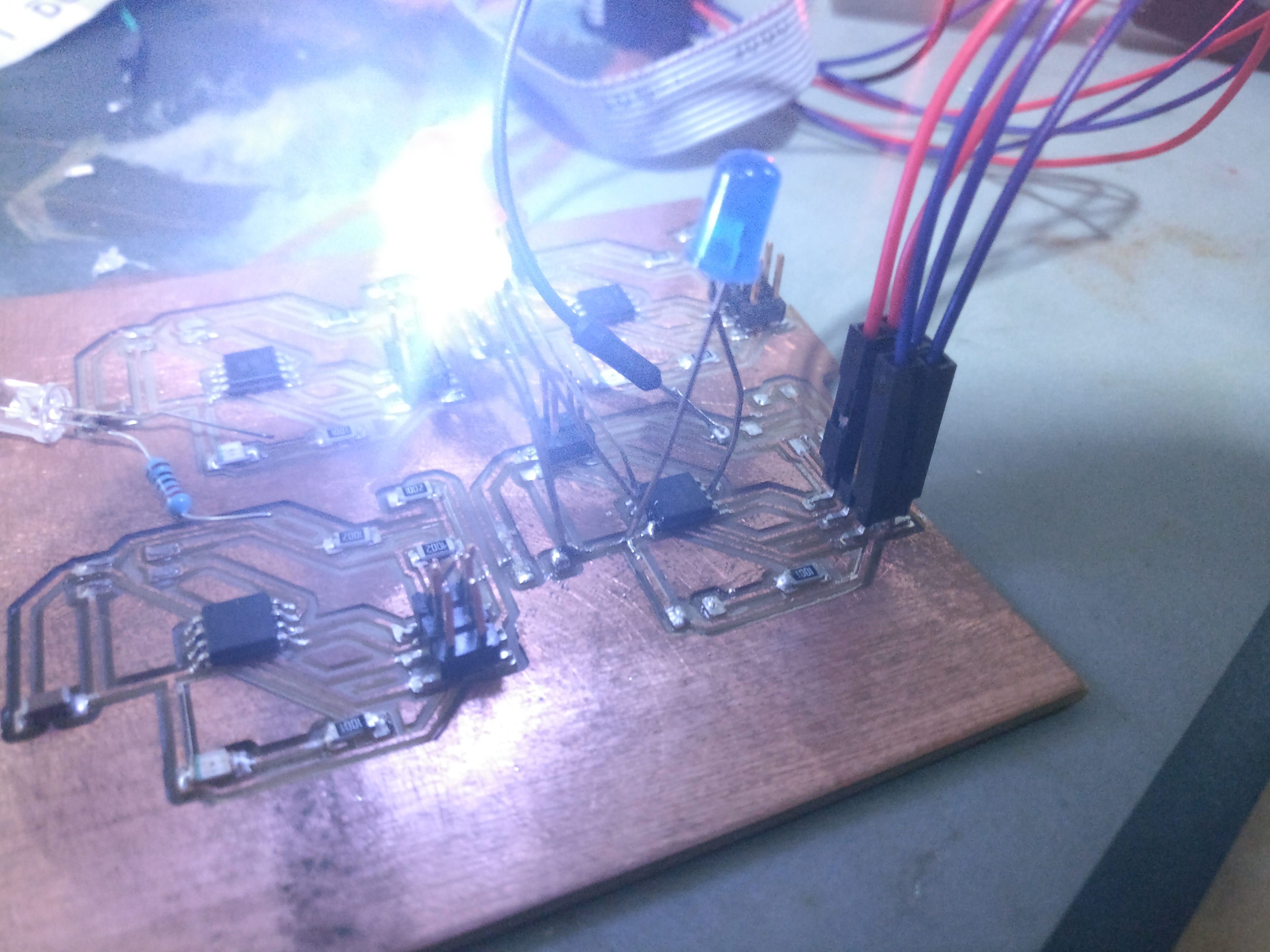
The only problem was, since the blue LED(output pin 1), jumped the SCK pin to ground I had to only solder one side of the LED. That way when I want to flash a new program I can bend one of the LED's leads up to allow the program to flash and then bend it back down so the LED would light as the program ran. Not the most eligant method, but it worked. That being said, if I were to design and cut another board I would add a latch/switch so the above would be done automatically. |
Finally, to wrap it up here is a video of the board working. I call it blue, then blue, and supprise it's another blue. Below is some code, but its quite simple. It's up to you to add more to it and make your own flashing light pattern with digital write high/low commands. |