Final Project
Presentation Video
Warning: The followng webpage is largely a haphazard (and repetitive) wall of text. Proceed with caution coffee
Final Project
Presentation Video
Warning: The followng webpage is largely a haphazard (and repetitive) wall of text. Proceed with caution coffee
Initial Project Design: ChalkBot
I initially planned on ctreating the ChalkBot as my final project. The chalkbot is a robot that was designed to drive around with a piece of chalk, drawing on the ground behind it. It would have been able to toggle the chalk on/off. I planned on developing two input methods:

However, as Fab Academy progressed, I realized that the ChalkBot wouldn't use much of the making potential of
the Fab Lab. It would really only use the lasercutter and milling machine, and there is much more avalible in the FabLab. After deciding to stop planning for this project, I was left without any plans for a final project for at least four weeks.
New Project: Flight Controls/Display
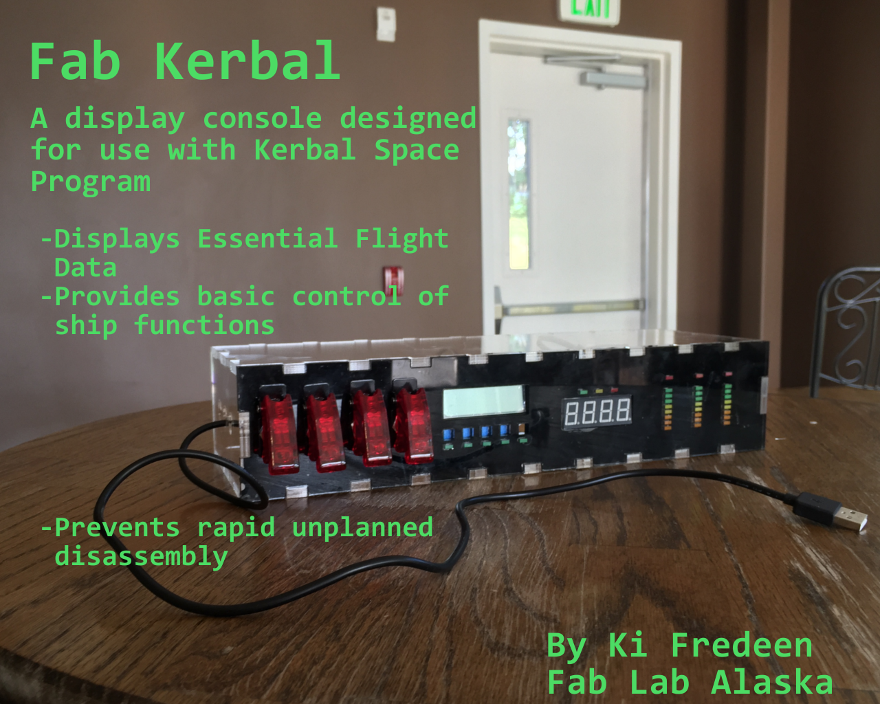
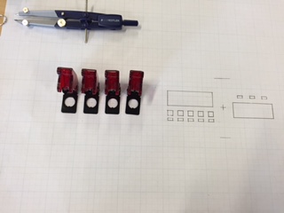
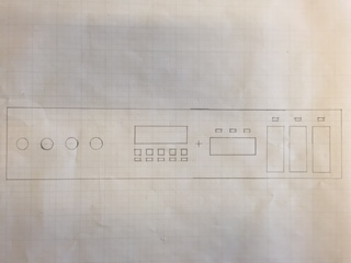
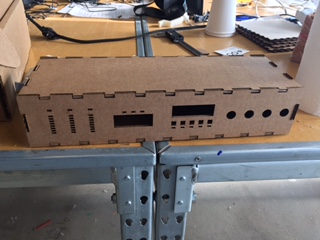
I now plan on making a flight data diaplay for use with Kerbal Space Program (and possibly other flight sims with a bit of tweaking). The display will retreive various flight data statistics such as air speed and altitude and provide warnings for low fuel, high G forces, and high aerodynamic stresses. It will also display fuel levels and orbital parameters. You can see the basic outlines of the display console below.
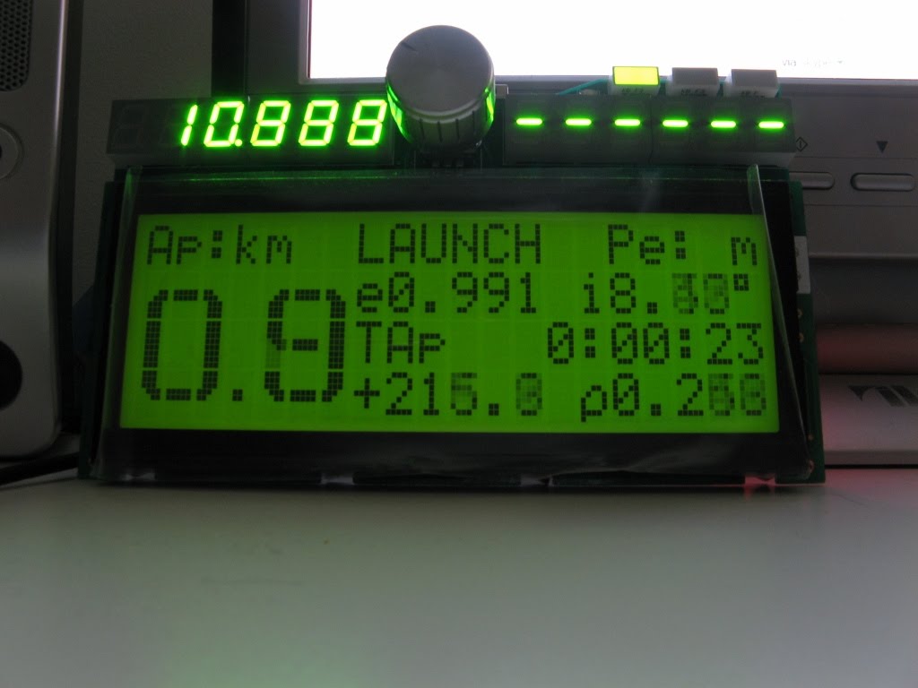
Many have done displays like this before for kerbal space program, and most of them can be found on this Kerbal Space Program forum thread. Many of these are much more complex than what I plan on doing for my final project. Communication between the game and these displays has been made easier with the KSP Serial IO plugin, but lacks control abilities on windows 10 computers (which I am unfortunately stuck with). Below is an example which is closest to what I will be doing.
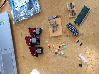
I will use either an Atmel 1284P, if I need a lot of program space and memory, or a 32u4, if I need easy serial communication and control. I will most likely use both at once. I will use smaller modules to drive the various components of he display, which will be driven by Atmel 328s and Tiny44s. We have toggle switches and LEDs, which will make up controls and fuel dispalys. I will also use a 4 digit LED display and an LCD. The exterior of the display will be acryllic and/or wood. These components will be sourced from our (admittedly outdated) local fab inventory (328, Tiny44, LCD, blank PCBs, sheet materials, and headers and resistors as needed), Digikey (32U4, resonators for 32U4), Amazon (switches and switch covers), Ebay (1284P), and local electronics stores (LEDs).
These materials will most likely cost at least 50 USD in total but may be somewhat over $100 if the expensive Alaskan shipping costs and mistakes are included.
Simplified BOM and list of locations to buy from:
Project overview
The Fab Kerbal is a display for flight data from Kerbal Space Program, a space/flight simulator that is difficult to master. I hope that that the use of this display will ease intermediate players into the more advanced aspects of KSP such as the difficult-to-take-off-and-survive-in aerodynamics and interplanetary orbital dynamics.
Schedule
While most people have until July 8 to finish everything, I really only have until June 26 to complete documentation (23rd for anthing hardware based), since I am going on a trip to some islands in the south pacific and will be without internet.
So far I have completed the functional hardware components, now all that remains is to get the box to work. Unfortunately, I have run out of time to complete any hardware modifications to acheive this goal, but I do have a list of tasks that would lead to the completion of my final project:
As you may notice, all but one of these steps require access to hardware I do not have at the moment (written on the 24th), but the big challenges of designing and creating the controller boards, the enclosure, and making the boards communicate with each other has been accomplished.
Since it is near impossible to finish my project before the deadline, I will attempt to document my project to the fullest extent possible within the next handful of days.
What has worked (and getting it to work)?
The assembly of the acryllic box has worked amazingly. I had started off by using the design methods I applied in CAD, Press Fit, and Big CNC, using a tab width of 1 inch, tab height of about .21 inches (thickness of the acryllic I was using) and various gaps between tabs depending on how many tabs I think I needed. The major difference in the process this time as my usage of the array tool to more easily create my tabs on the design.
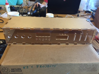
I first applied the design to a cardboard prototype, to see how well the joints fit together before using the relatively expensive acryllic. The joints fit together well, but were a bit loose since cardboard cutting tends to have a wider kerf than acrylic cutting. I then took the prototype home to see if it would fit under my monitor, and it did.
Knowing the joints work, I then moved onto the
cutting of the acrylic. I used really clear plastic, since I wanted to be able to se all the hard work I put into the electronics and also to see if one of the boards had caught fire.
![]()
The acryllic cutting was slow, since I wanted to make sure that the machine cut all of the way through on the first try. It did, and I ran the same file again, this time only the front and bottom panels without the holes to make the rear and top panels. In hindsight, I should have put a hole or two in the top for easy removal of the lid later on. I test fit the pieces before the final assembly.
But before the final assembly, I placed some black vinyl on the back of the front panel to give a very nice obsidian-like effect that is hard to convey in a photo. This was very time consuming, since I couldn't be bothered to align a cut vinyl pice up with the holes and I ended up placing a whole sheet over the panel and cut every hole out individually with an exacto knife.
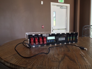
The final assembly required some skill, since the "adhesive" I was using was a very strong solvent of most plastics and was known to be a carcinogen. The goal was to dissolve a little
bit of the acrylic at the joints and have the acryllic repolymerize (?) together, forming a very strong bond after the solvent dried completely (I demonstrated this by accidentally dropping my final project just before presentations). overall, the finished box looked amazing and displayed the (incomplete) internals of the box quite nicely.
The next things that worked were the boards and the communication between them. Communication already proved to be working well in networking, where I tested the communication between the 328P I2C node and the Tiny44 I2C node. The boards individually worked well for their individual tasks, and I made and tested them in input devices, output devices, and interface and application programming. Serial communication works as well and was tested in interface and application programming.
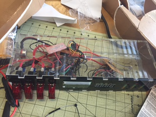
After I returned from my trip, I began work on completing the functionality of the board. this began by wiring all of the visible components to their respective control boards. This produced quite a mess of cables inside the console that was only partially fixed the careful application of zip ties.
I also created two different boards to make attaching components easier. The first of these boards were the boards I attached the buttons to. I designed these boards to be small so that they can fit between a row of LEDs and the LCD above it. I also included a resistor so that I don't accidentally draw too much current from a pin. These buttons were attached to the main board, since the LCD control board did not have enough pins left to control them.

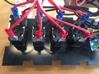
To install the buttons on the main pannel, I 3D printed some button caps that would fit in the square holes on the front of the panel and superglued them onto the buttons. I then installed the buttons and hot glued the boards into place.

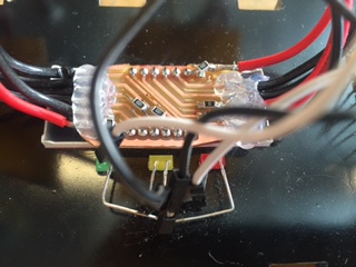
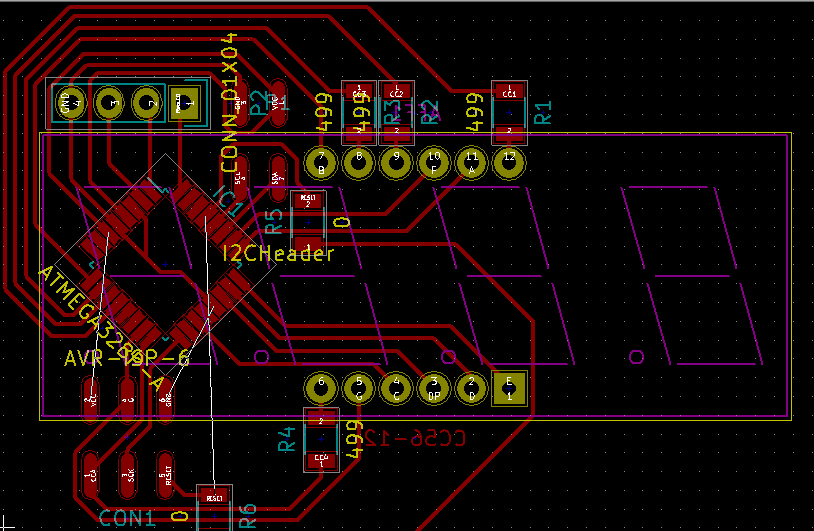
The second board allowed me to attach wires to the 7 segment display. I did this because the dedicated board I created for this purpose wouldn't program, so I needed to make the pins on the display easily accesible.
The board includes resistors to avoid drawing so much current that the LEDs fry.

In the end, it turns out that I made mistakes while laying this board out, and placed the connections wrong. I rectified this with an xacto knife anda few more resistors (seen below where I discuss the internal wiring).
With all the boards hooked up, I could begin programming the boards. Since the software I was going to use for communicating with the game was not working, I wrote a test program
that could control what is sent to the console manually.

I then wrote a program for the main board that would handle serial communication with the computer and control the other nodes. It would read a set of strings, save and distribute them, and send back which switches are on and off.
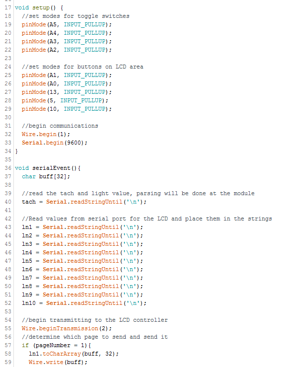
The individual controllers are programmed to perform their job with the data they are given. The LCD controller writes two strings on two lines of the LCD, and the strings will change depending on which button is pressed
After writing this code, I hooked up everything inside the box. I used blade connectors on the toggle switches, cut up prototyping wire for the LCD, normal copper wire and a custom board (seen above), two raw copper PCBs for power distribution, and ribbon cable for the I2C interface.

I wrote two more pieces of code, one to control the seven segment display given a number, and another to control an LCD given a character and a string.
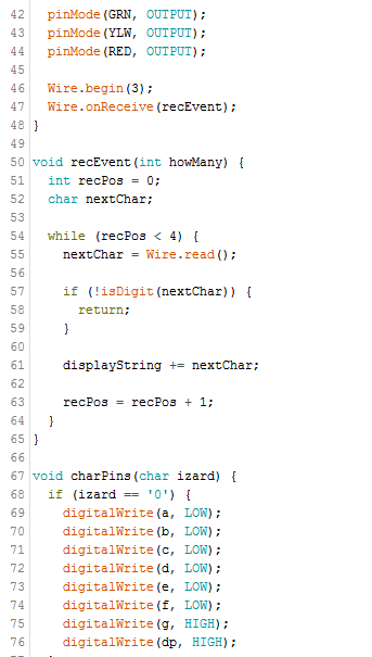
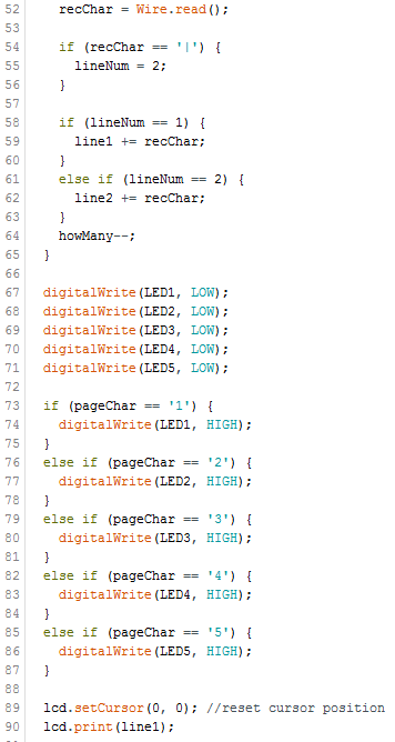
The LCD program takes the data byte by byte (that's how the I2C works), where the first byte will indicate which page LED to turn on, and the preceding bytes are the string, which is pieced together character by character. I used the "|" character to indicate where the next line should be.
The 7 segment program
takes 4 bytes as a string, pieces it together, and writes the number on the display. The difficulty I had with writing this was the display pinout and where they connected with the board. To rectify this issue, I made a makeshift datasheet (seen below) that mapped segments to pins, and then I carefully traced the connecting wires to the respective pins on the board

Whille preparing the boards for a test, I discovered that I had wired the USB wrong on the 32u4 board for external power. when I plugged both the external power and the USB, the positive trace broke from the overcurrent at some place or another. I fixed the issue by making a new board with UBUS not connected to positive, and excluded the 1284P for simplicity.

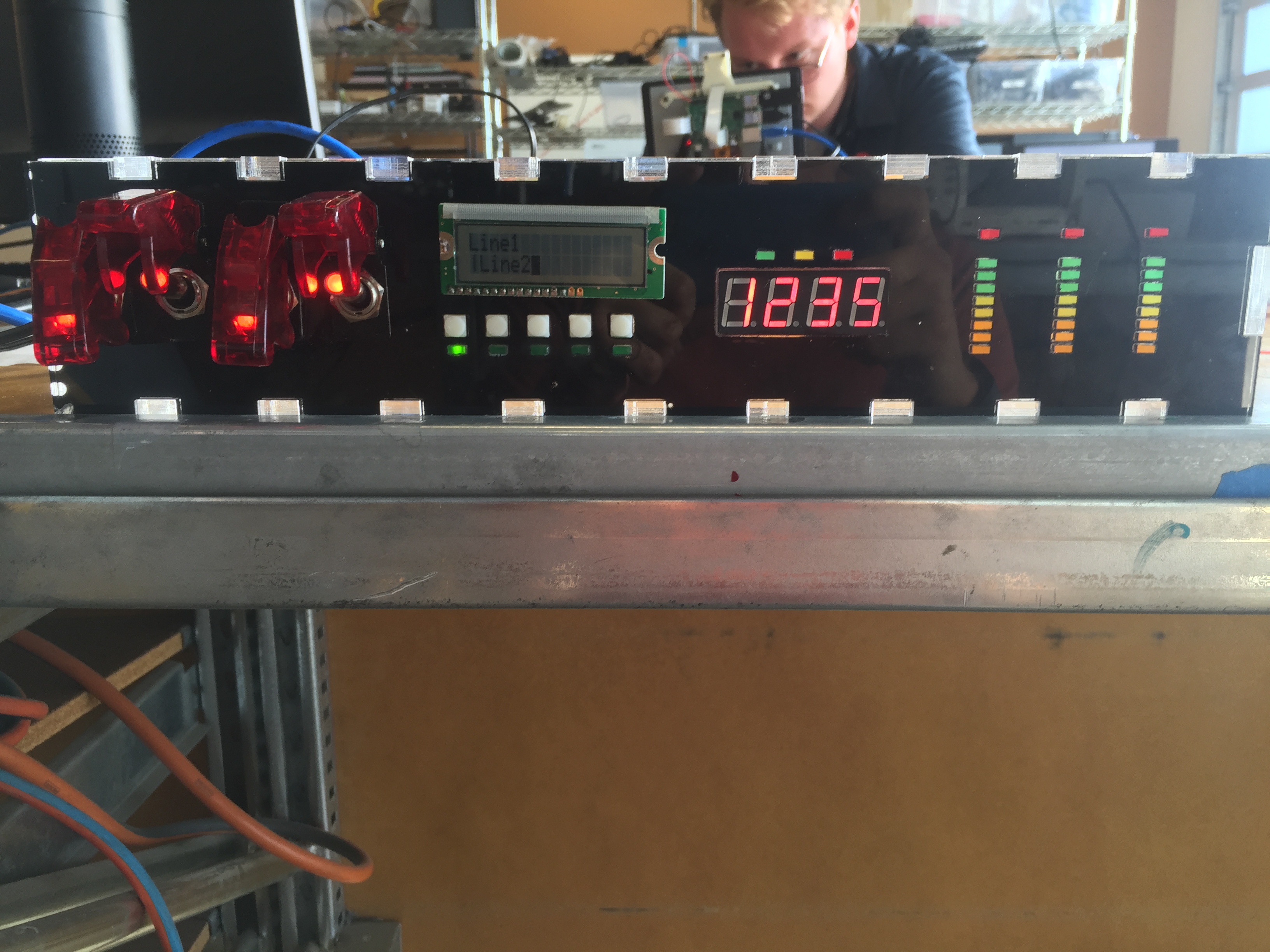
I finally got to test the
whole system out. these were the inputs (also the switch results, it was easier to catch all at once) I set up in the program I wrote:

And this was the result:
Things that didn't work out
One of the major things that didn't work out was the dedicated board I had created to control the 7 segment display I had on the fromt of the board. It was designed because creating a board with shift registers for use with my Tiny44 node was not turning out well, and I needed a quick solution. I designed and manufactured this board only to find out that my ISP refused to program the chip. I had replaced the chip several times, fixed the
USB connector on the ISP, and even created a dedicated power delivery ISP cable. In the end, I ditched the board and used one of my highly reliable 328P nodes to control it.
Another thing that wasn't working was the serial communication between my main board and the game. The plugin that was designed to do this did not work in Windows 10,
being able to send information but not receive it. This was fine since the sent data would be easy to display, and the received data was primarily controls that could be handled by the 32u4. However, in the long term, the benefits provided by the received data would be crucial to the development of my final project.
I never got the bar graph LEDs to work either, since there was simply too many pins to control. In the future, I could implement some shift registers or bar graph drivers to drive these graphs off of another controller.
Questions that still need to be answered/solved:
What have I learned?
In the course of making my final project I have learned (from scratch) basic electronics design, the programming of microchips, and more advanced 2D design than I had known before. These were the lessons learned the easy way, through experience, reading, and trial and error.
The lessons I learned the hard way were in some ways the most important. Examples of such lessons are what happens when an unprotected microchip has the power polaity reversed on it, Identification of a frying microchip in progress, what happens when you overvolt LEDs way past their rating (explosions), and setting things up right the first time.
I learned that modules need a common power source to communicate effectively, and that datasheets should be read in depth before putting microcontrollers on a board.
A very handy lesson I learned was how to create circuit boards with the laser cutter, allowing me to use chips that I couldn't with the mill.
Weeks that I worked on parts/concepts of my final project, and other things
Input Devices - Tiny44 node
Output Devices - 328P node
Networking - I2C communication
Electronics Production - ISP I still program everything with
Business Stuff - Where I chose my license
Final Control Board - The main control board of my final project
Etching Process - The chemical etching proocess I use to create my boards
Plugin - link to the forum page of the plugin I planned on basing the code of my project on
Interfaces - where I made the testing inteface for the project.
Project design files, both the ones I used and the ones I didn't use
TinyI2CNode.zip
- KiCAD files for the ATTiny44 node I planned on using for small things and didn't
328I2CNode.zip
- KiCAD files for the 328P node I use for almost everything
I2CCore.zip
- KiCAD files for the core I2C controller
I2CCore2.zip - KiCAD files for the correctly wired update without the 1284P
328I2CNumbers.zip
- KiCAD files for the failed 7 segmet controller using the 328P
Panel.crv3d
- Aspire file for the enclosure of my final project
FinalPanelPt1.ai
- First Adobe Illustrator file for the enclosure of my final project, including most parts
FinalPanelPt2.ai
- Second AI file for the enclosure, including everything else
New7Controller.ino - Arduino code for 7 Segment controller
NewLcdController.ino - Arduino code for the LCD display
ConsoleTestProgram.zip - VS source/executable for the test program
MainControl.ino - Board side code for my final project
License:

Fab Kerbal is licensed under a Creative Commons Attribution-ShareAlike 4.0 International License.