LED Growlights
When you start looking into indoor growing systems, you will soon notice that many systems use a pink-purple-ish hue of light. Why, when in the wild, plants grow under full-spectrum natural sunlight, would you bath your plants in pink light?
Taking a step back for a moment to high school physics lessons, you may remember that objects appear the colour they appear because of the wavelengths of light they reflect and absorb. White things are white because they reflect all visible wavelengths of light, black things are black because they absorb all visible wavelengths and reflect nothing, green things (like leaves) appear green because they reflect green wavelengths and so must absorb light in the red and blue wavelengths.
So if leaves absorb and make use of only red and blue wavelengths, it is not necessary to give them green light. Therefore you could increase the efficiency of a grow light system by providing only what the leaves will actually use for photosynthesis. Once the green portion of white light is removed, you are left with the red and blue wavelengths, hence the pink-purple colour typical of many indoor growing systems.
This simple idea of providing only what is required makes a lot of sense to me, and has led me to ponder another theory… But I’ll come back to that later!
Designing the LED Array
In fact, it is the chlorophyll in leaves which allows plants to absorb the energy from light by resonance energy transfer, which is cd essential for photosynthesis. Chlorophyll molecules are arranged in photosystems, which by current understanding, can be categorised into two distinct units: P680 (Chlorophyll A) and P700 (Chlorophyll B), so named according to the wavelength of their absorption maxima in nanometres.
 Absorbance spectra of chlorophyll a and b
Now the question is, for optimal growing conditions, what proportion of red and blue light should I provide? The answer is: it depends! It depends on the concentrations of chlorophyll a and b present in the leaves of the particular species of plant in question.
So ideally, my grow lights should have a degree of flexibility - it should be possible to tune the light “recipe” for whatever is being grown at the time.
Enter NeoPixel LEDs!!!
The SK6812 Integrated Light Source (or NeoPixel as coined by Adafruit) is a red, a green and a blue LED plus a driver chip all packaged into a single surface-mount component. They are individually addressable RGB LEDS, allowing each one to be controlled separately. NeoPixels will be very handy for this project as I will be able to control the colour of light in software using a microcontroller.
Adafruit have put together a NeoPixel Überguide which proved to be incredibly helpful in getting the grow light to work!
Luckily, fellow Fablabber Niklas had 50 SK6812 NeoPixels left over from another project, which he was happy to donate towards the cause, and also give some valuable pointers. Thanks man! NeoPixels can be wired in series with a common signal used to control the individual units. From the SK6812 datasheet:
 SK6812 typical application circuit
I decided to make the grow light in modular sections, so I could have an extensible system that could be made bigger or smaller simply by adding or removing modules. I started by scribbling out what I thought could work:
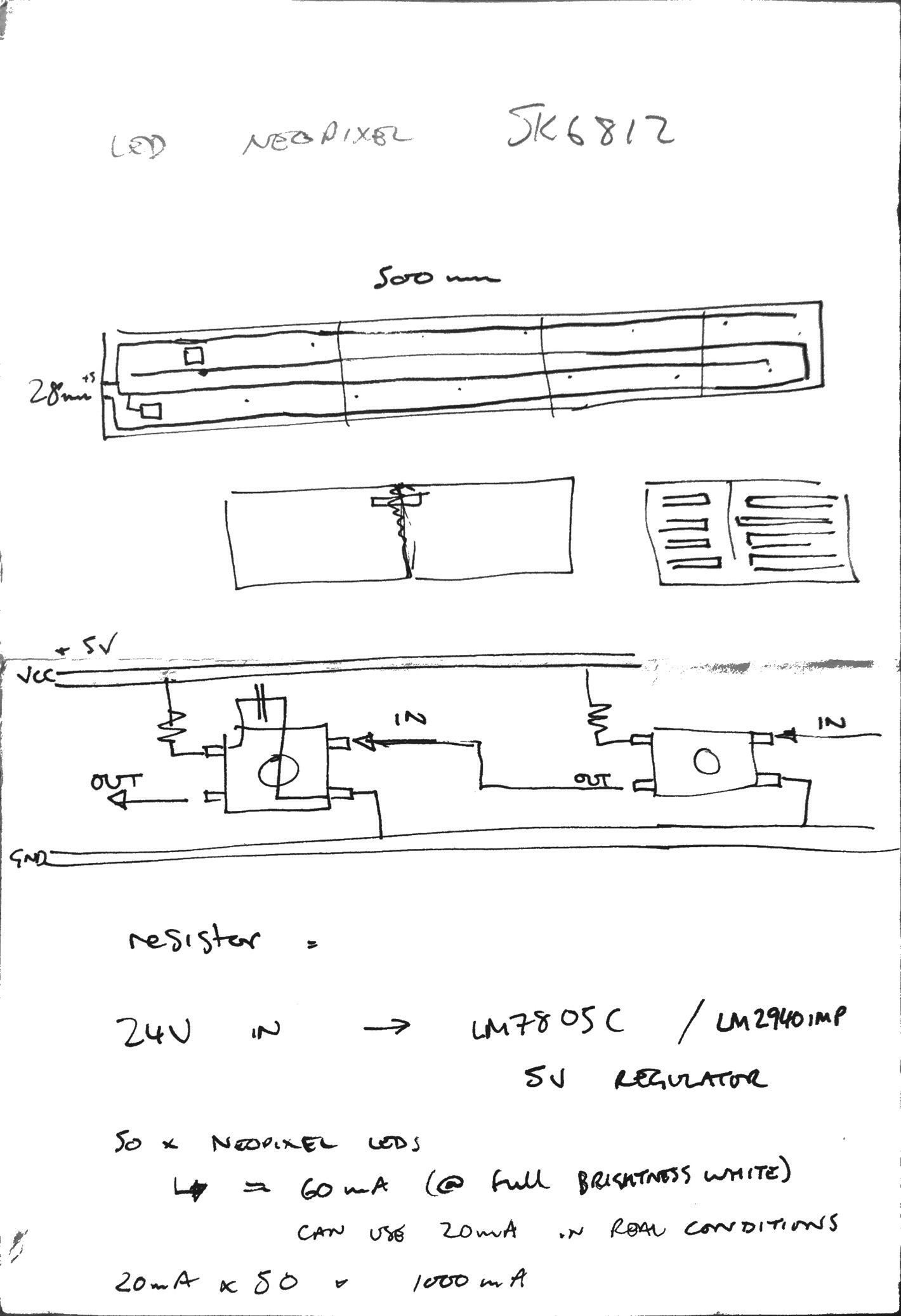 First sketches of the modular grow light
There’s all sorts in this sketch, but you can get the idea of what I was aiming for. From the top, you can see how I was thinking to run the traces between the modules, and how I might connect them just below that. The third scribble gives a bit more detail. I have shown a resistor between VCC and the NeoPixel (the idea was to regulate the current, but it turns out that wasn’t necessary). There is also a capacitor between VCC and GND to smooth out any peaks or surges from the power supply and hopefully avoid damage to the LEDs.
After the Electronics Design exercise in week 6 where I had a hard time using 123D Circuits to design my board, I opted to download and fire up Fritzing. I found it much easier working in Fritzing, although it has it’s own nuances, I managed to get what I needed out of it faster and with less frustration.
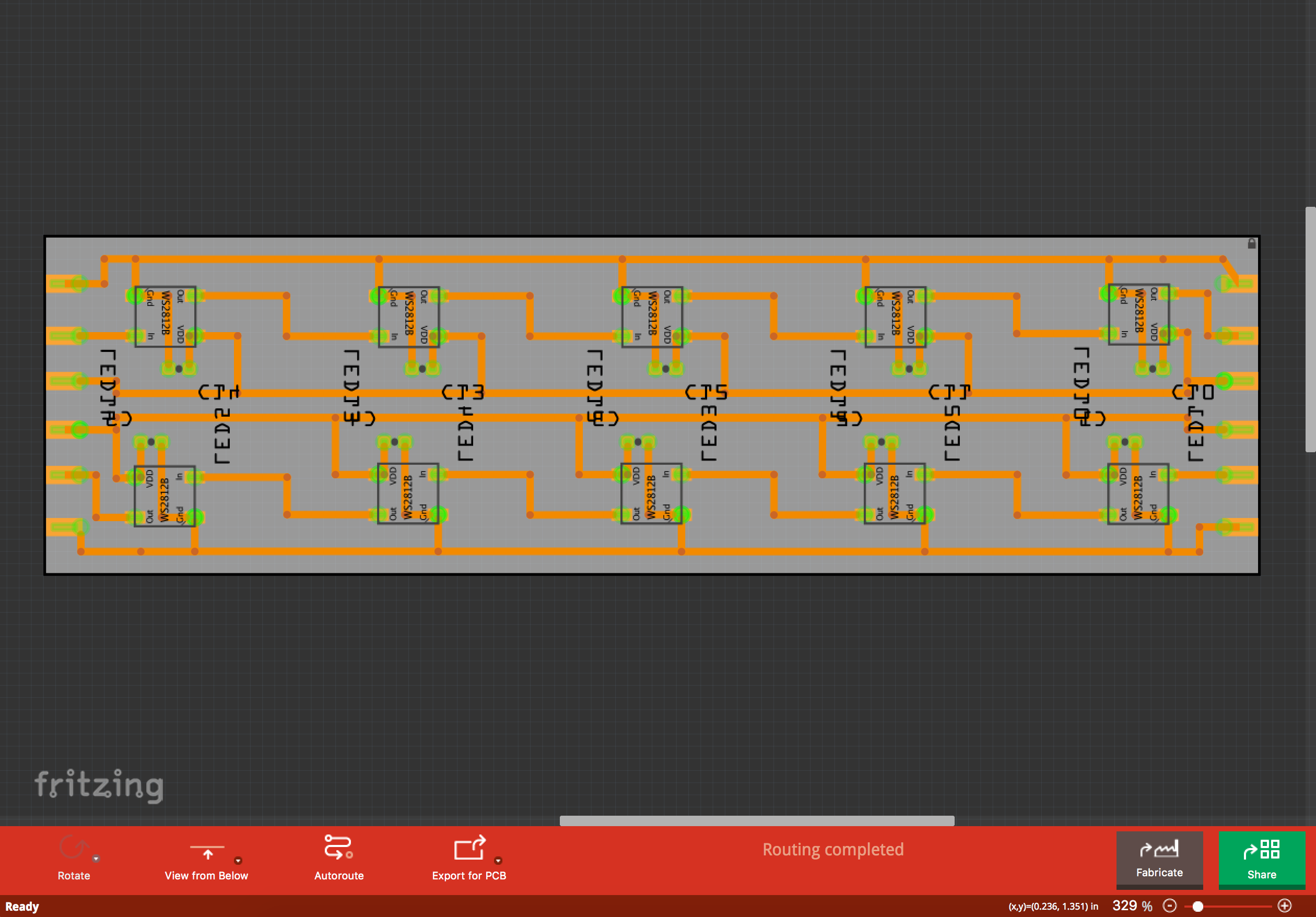 First go at the PCB layout in Fritzing
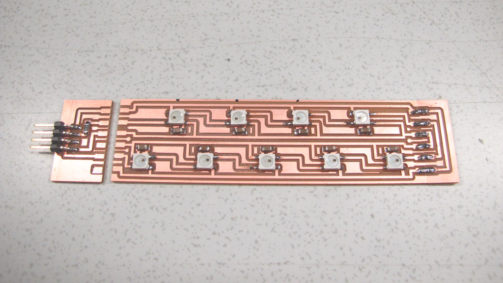
The module has 10 NeoPixel LEDs, with the GND running on the outside edges, the signal passing between the LEDs from IN to OUT in left to right across the top row and back again from right to left for the bottom row (eventually this would become a clockwise loop with an end module). VCC runs in a similar way on the inside.
I decided to stagger the LEDs to try to distribute the light more evenly along the length and eliminate a few LEDs from the design. This resulted in my final 9-NeoPixel module.
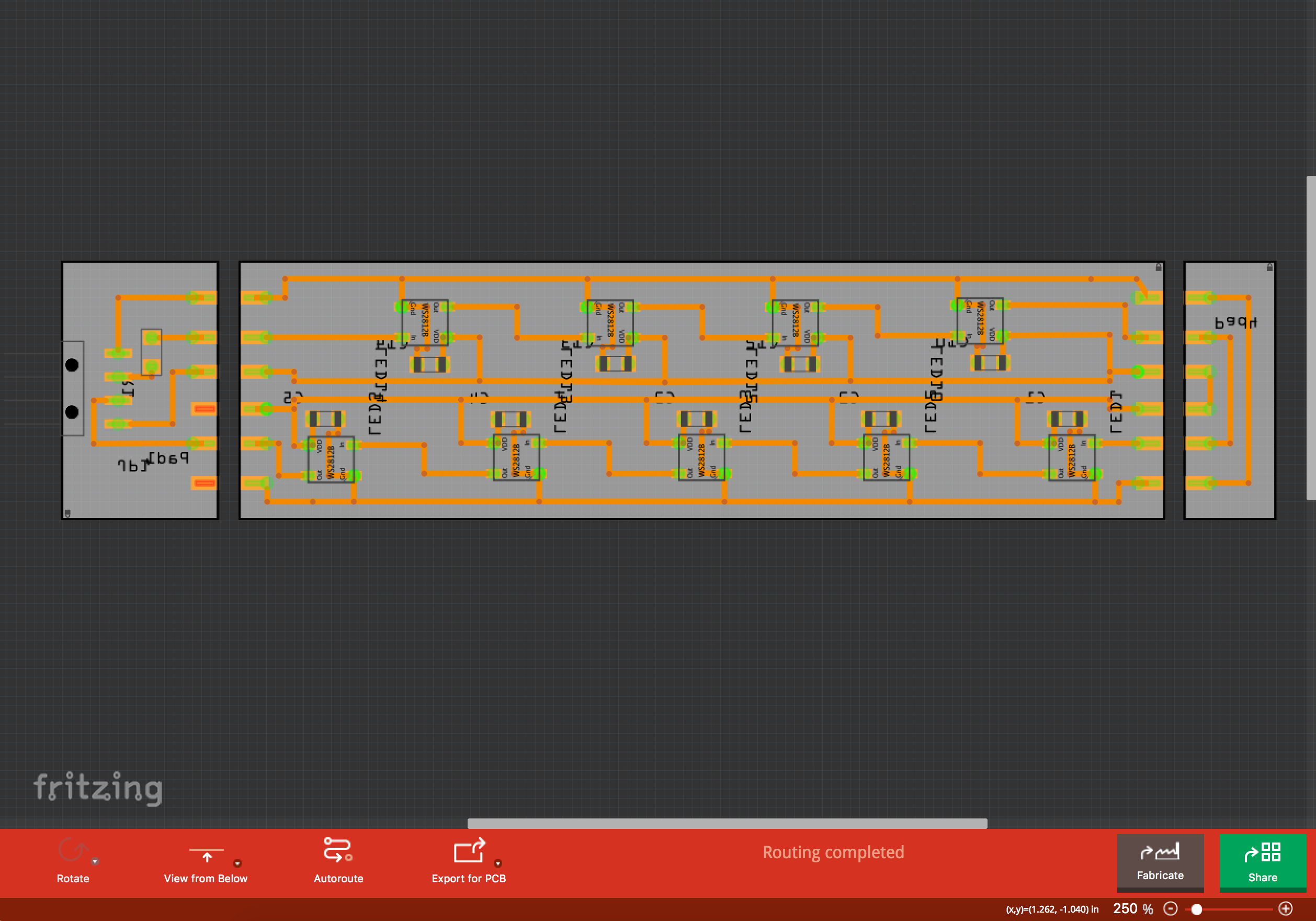 Final PCB design with start module, 9-LED module and end module
The start module indcludes a 4-pin horizontal header and a 497Ω resistor on the signal line before the first NeoPixel, as per the Adafruit NeoPixel Überguide best practices, which should prevent spikes in the signal and protect the first pixel.
Making the Modules
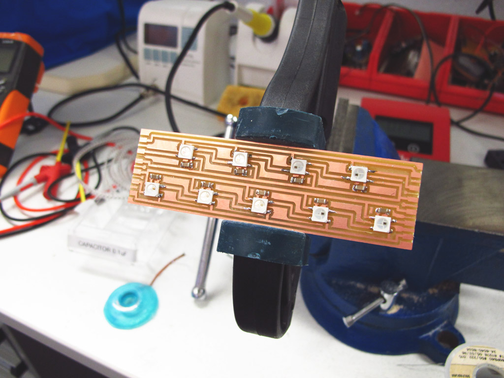
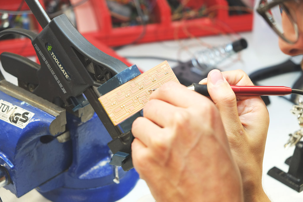
I exported pngs from Fritzing and milled the modules on the Roland MDX-20 using the Fab Modules as in previous weeks. The milling went smoothly and I set to work with the soldering iron. I got myself set up with my improvised vice-quick-clamp helping hand, a set of opposite action tweezers (squeeze to open) and got to work!
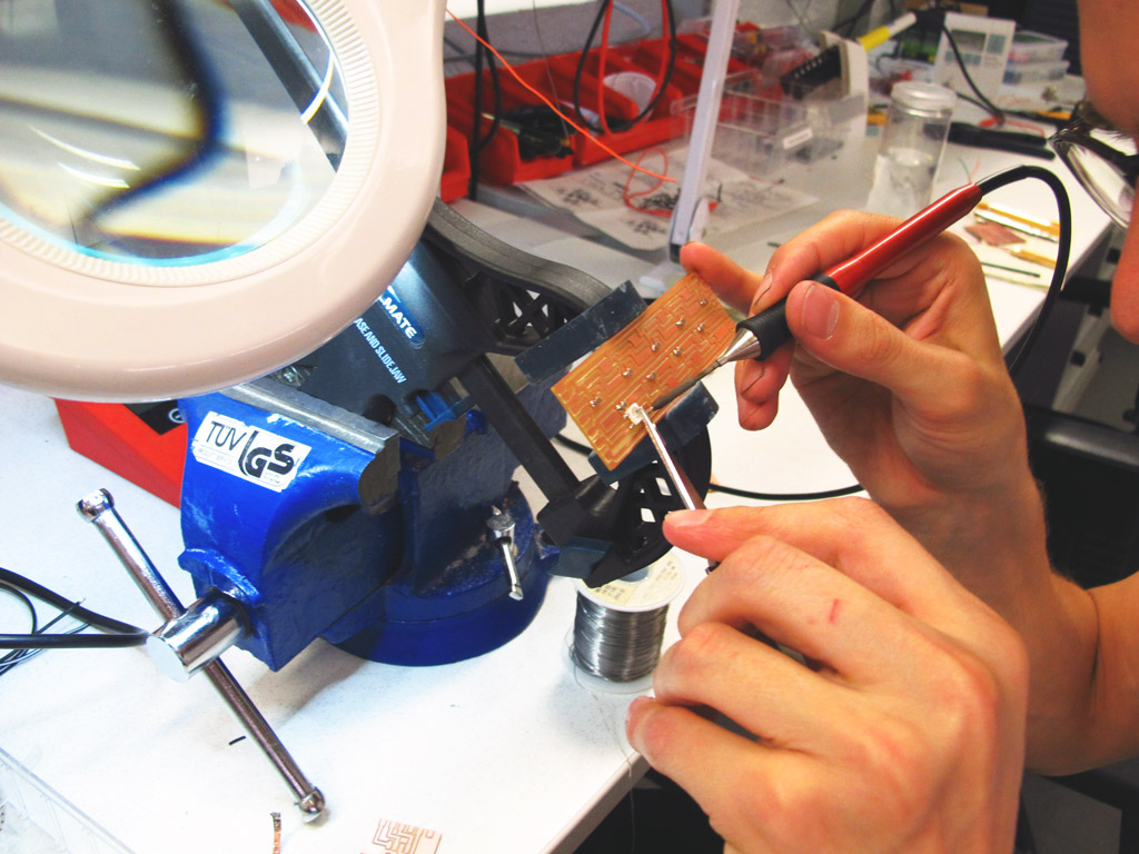 Soldering, capacitors first, and pinky for stability
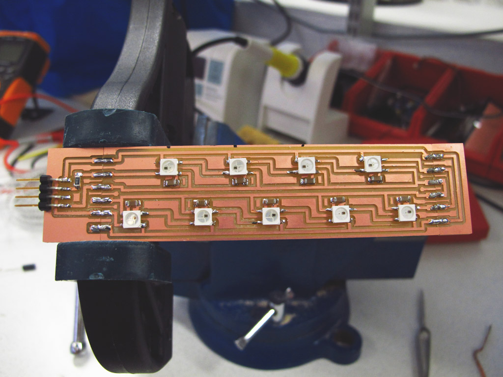
The pixels were a little tricky to begin with. I used the method of laying a small amount of solder down on the pads first, then re-flowing onto the feet of the NeoPixel packages. After the first few, I got into a rhythm and just used is as extra practice!
 9 LED module done!
Next it was time to prepare the start module and close the circuit with the end module.
 End module attached, start module ready and waiting
 Start module soldered, completed unit
Quick Test
With the unit soldered and ready to go, it was time to try it out to make sure everything was working as expected. I used an Arduino Uno with the strandtest sketch from Adafruit’s NeoPixel Arduino Library and a 5V power supply made from an old mobile phone adapter with a 1000uF capacitor for surge protection.
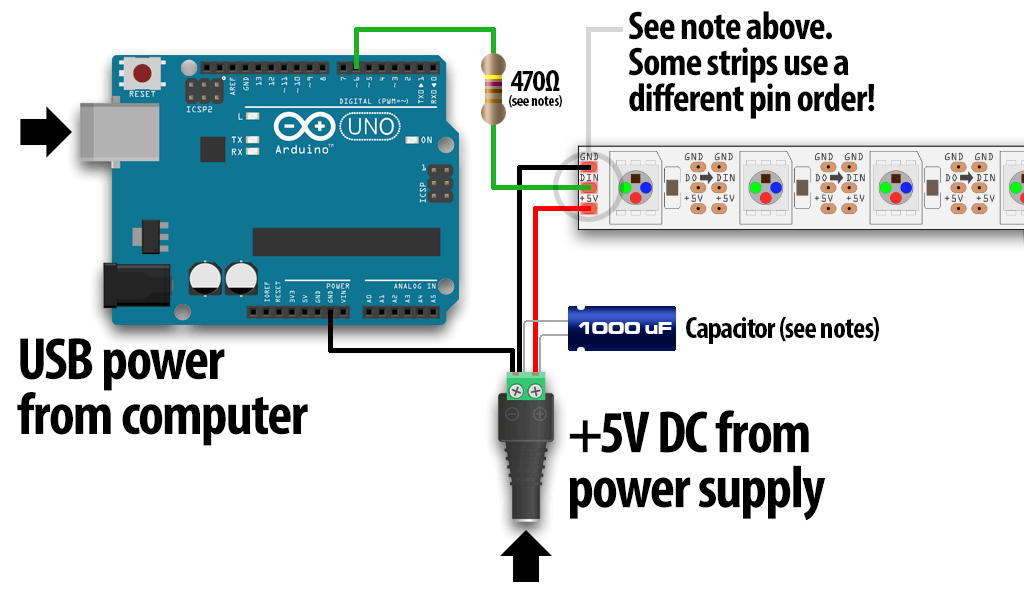 NeoPixel Test set up using an Arduino to produce the signal
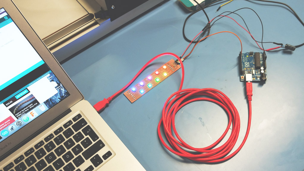 Single module unit running the strandtest sketech from an Arduino Uno
The test worked beautifully, so I went ahead a made 4 more modules and hooked them up to make a 45 LED unit!
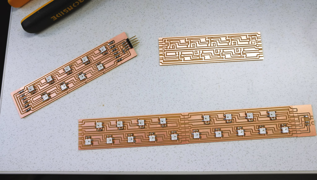 The whole family of growlight modules in various states of completion
 Ramping up production speeds by first laying down a bead of solder
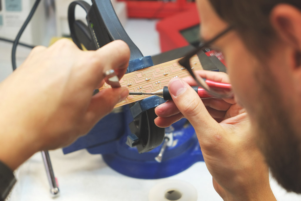 Reflowing the solder when placing the capacitors
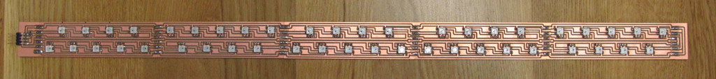 The full 45 NeoPixel LED Unit soldered up!
I wrote a simple sketch using the Adafruit NeoPixel library to try the 45 LED unit:
#include <Adafruit_NeoPixel.h>

#define PIN 0

// Parameter 1 = number of pixels in strip
// Parameter 2 = Arduino pin number (most are valid)
// Parameter 3 = pixel type flags, add together as needed:
//   NEO_KHZ800  800 KHz bitstream (most NeoPixel products w/WS2812 LEDs)
//   NEO_KHZ400  400 KHz (classic 'v1' (not v2) FLORA pixels, WS2811 drivers)
//   NEO_GRB     Pixels are wired for GRB bitstream (most NeoPixel products)
//   NEO_RGB     Pixels are wired for RGB bitstream (v1 FLORA pixels, not v2)
//   NEO_RGBW    Pixels are wired for RGBW bitstream (NeoPixel RGBW products)
Adafruit_NeoPixel strip = Adafruit_NeoPixel(45, PIN, NEO_GRB + NEO_KHZ800);

void setup() {
// put your setup code here, to run once:
strip.begin();
strip.show();
}

void loop() {
// put your main code here, to run repeatedly:
for(int i=0; i<strip.numPixels(); i++) {
  strip.setPixelColor(i, 255, 0, 77);
}
strip.show();
}
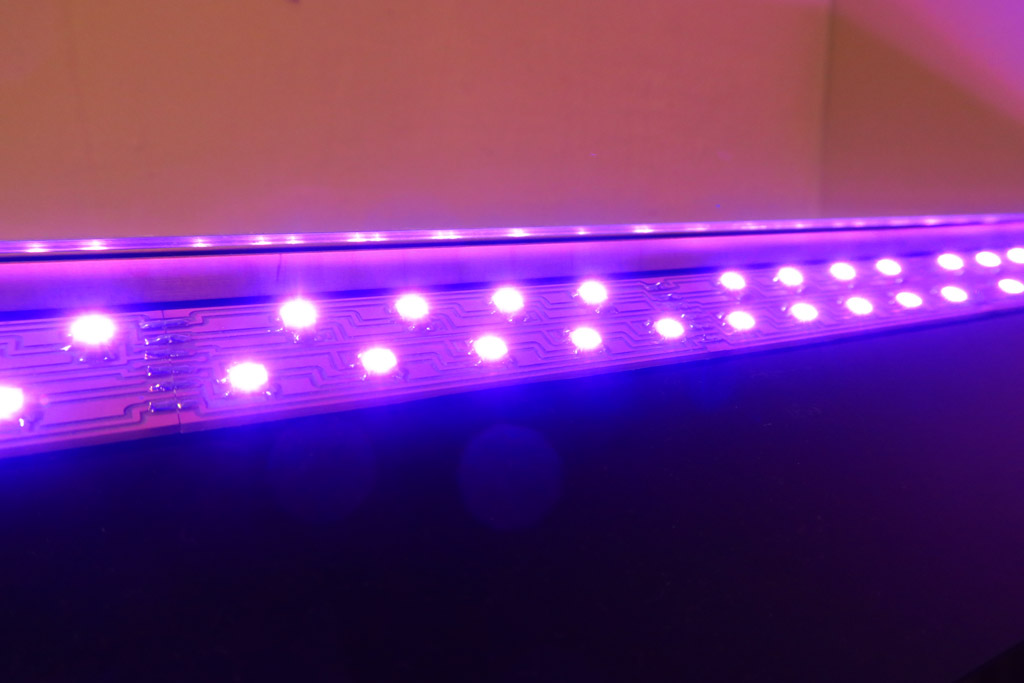
 The 45 LED Growlight with an Arduino running my growbox_neopixel sketch
This also worked beautifully, so now I just had to make it work with a self-made controller!
The Controller
My plan for my final project is to have a single controller board, with a single power input, reading data from water level and light level sensors, driving the NeoPixel LEDs and also controlling the watering system. My concept diagram looked like this:
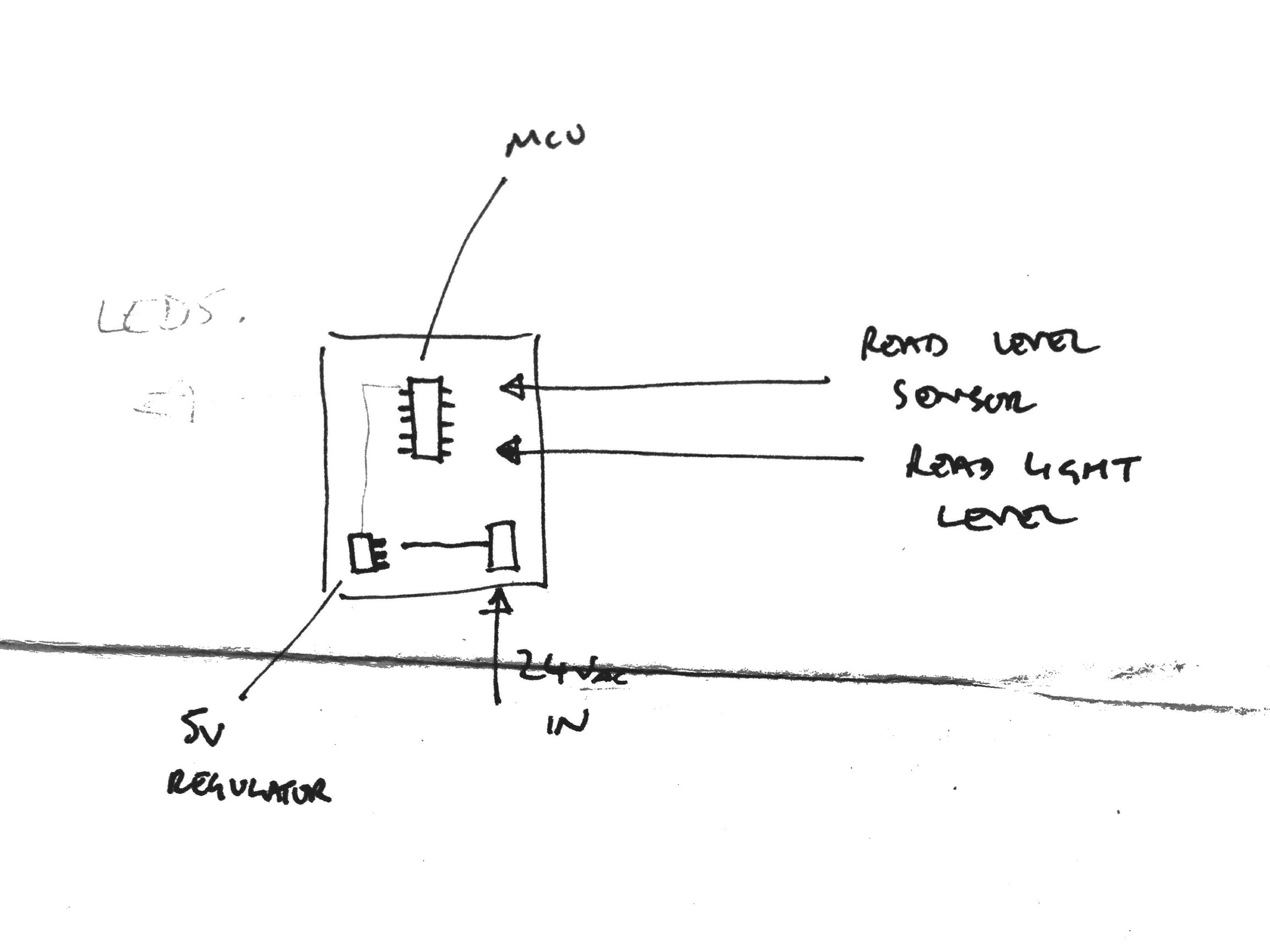 Controller concept diagram, showing what inputs and outputs would be required
I started looking into the idea of using a 24V AC supply (which would be needed to run the ultrasonic fogger I plan to use) with a regulator to bring the the supply down to 5V for the MCU and LEDs. I quickly got out of my depth, so decided not to go in to that just yet and focus on getting the LEDs running from my own microcontroller board.
Using only one plug is a key design criteria, so I’ll come back to this in the final project build.
The controller uses an ATtiny44 and is basically a FabISP with a 5V DC input.
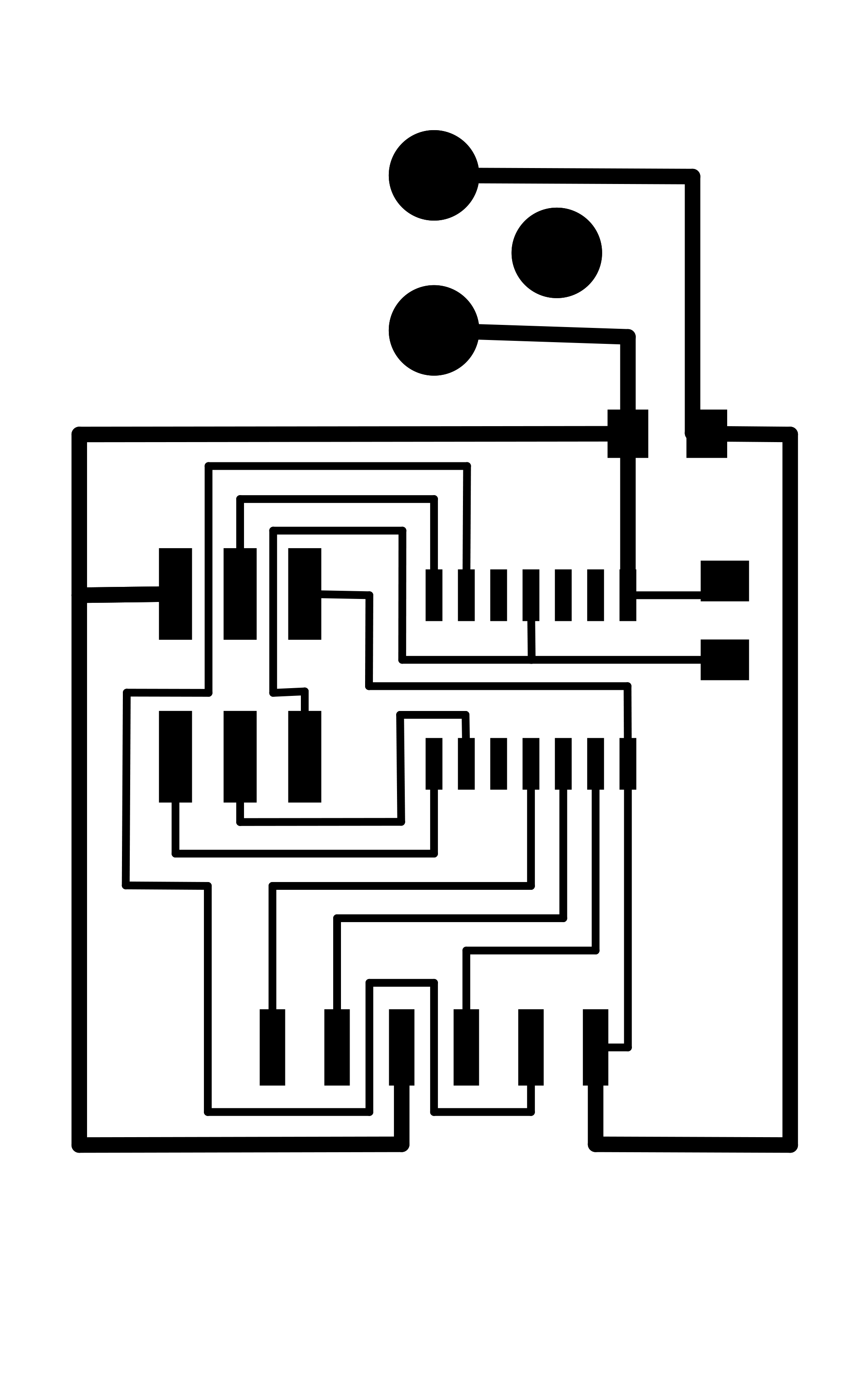
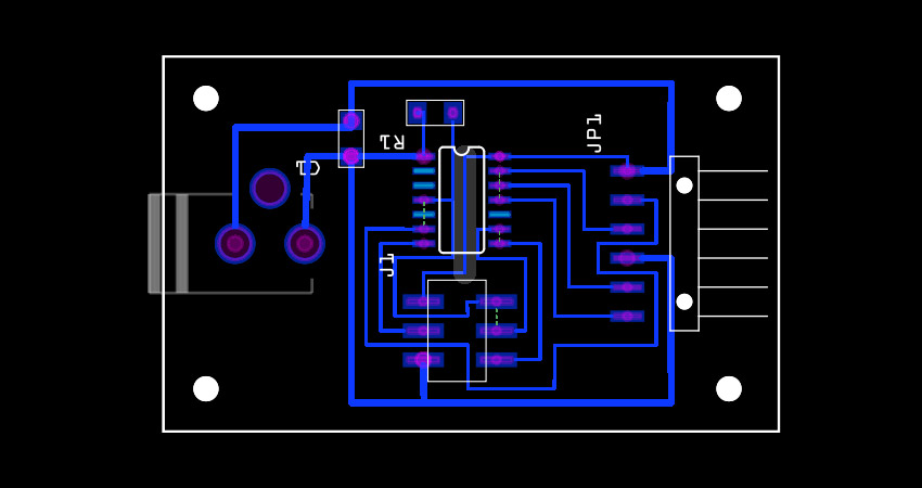 Controller PCB design
Programming the Controller
I had already got the LEDs working using an Arduino, so I decided to use the same sketch and program the new controller using the Arduino IDE.
First thing to do was to install ATTiny Core to enable support for ATtiny processors in the Arduino IDE.
Once installed, I chose the correct board, processor and clock speed settings, then hooked the controller up to my computer via the FabISP.
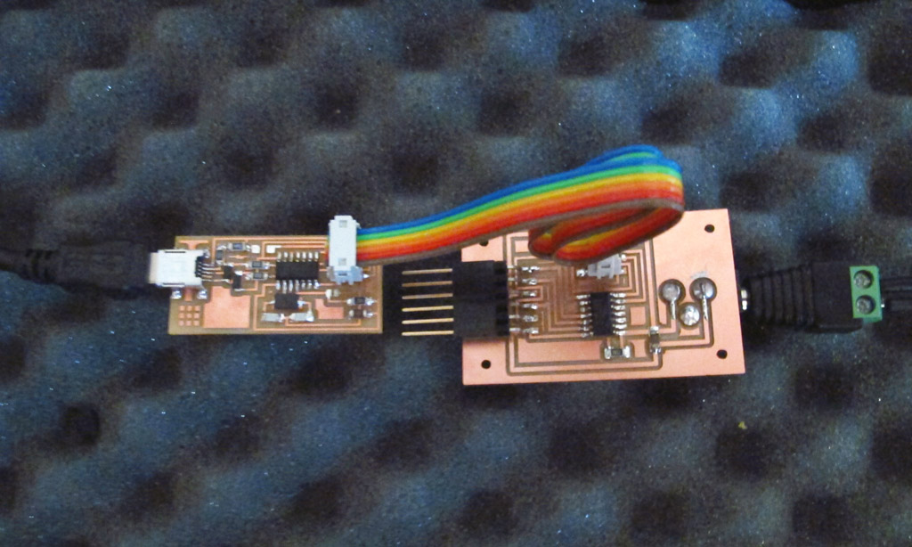 Controller hooked up ready for programming
I selected the programmer type and hit Burn Bootloader, then compiled and uploaded the sketch to the board using Sketch > Upload Using Programmer.
I hooked up the controller to the growlight unit and got this:
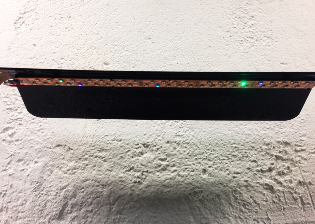 Growlight with signal from my controller board
Not exactly what I was hoping for!
A few random LEDs are lit in blue and green and various intensities, but that’s quite far from a consistent violet hue!
According to Adafruit’s NeoPixel Überguide, the SK6812 is sensitive to signal timing. Since I am using the ATtiny44’s onboard clock at 8MHz, which is not very accurate, it may be that the timing is off. Perhaps an external crystal is needed to set the clock accurately?
Also, since my code uses the Adafruit NeoPixel library, it’s possible that the library is not being included correctly…
Debugging
I revisited the ATtiny44 datasheet to read up about which fuses I needed to set to get the mcu running as I wanted. As a little side note, the fuses are a few bytes of permanent storage on the chip that determine things like clock speed and operating voltage, etc. The fuses are stored permanently, so you get the same settings after powering the device on and off, but they can be re-set over again.
I also found from the datasheet that PB2 can be set to output the clockspeed. Using an oscilloscope, I measured the clock output, which seemed to be 2MHz! That could be a problem!
I used a fuse calculator to get the hexidecimal values of the fuse settings I needed.
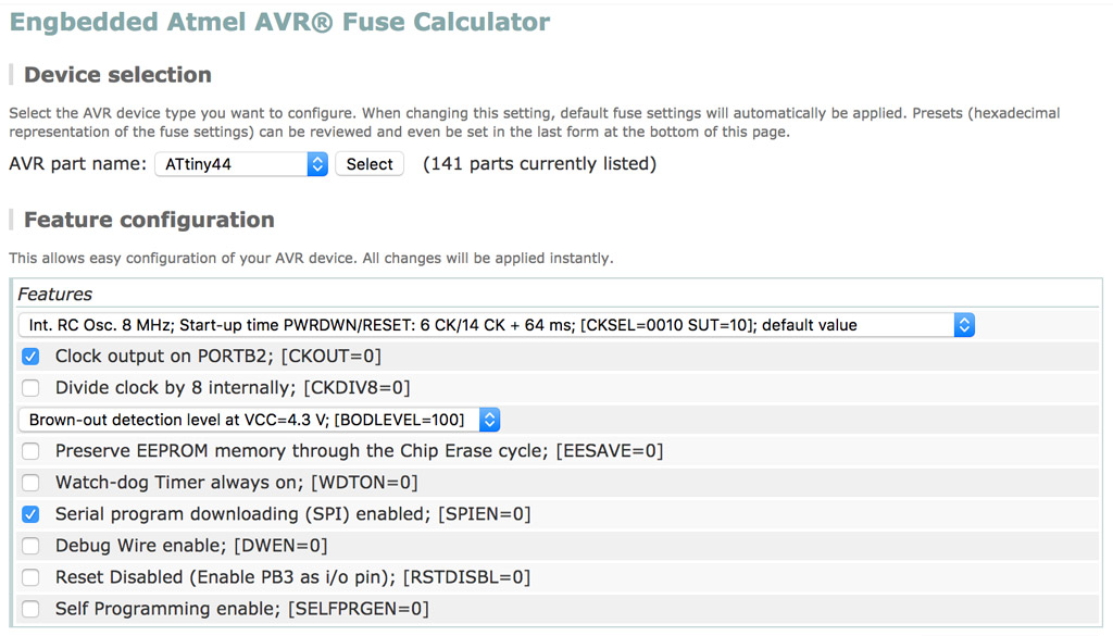 Parameters set for the fuse calculator to do it’s thing
The important ones to note are the 8MHz clockspeed and the internal clock divide CKDIV8 which was set to 0.
I opened up the terminal and typed (using the output from the fuse calculator above):
avrdude -p t44 -P usb -c usbtiny -U lfuse:w:0xa2:m -U lfuse:w:0xe2:m -U hfuse:w:0xdf:m -U efuse:w:0xff:m
which returned:
  avrdude: AVR device initialized and ready to accept instructions

  Reading | ################################################## | 100% 0.00s

  avrdude: Device signature = 0x1e9207
  avrdude: reading input file "0xa2"
  avrdude: writing lfuse (1 bytes):

  Writing | ################################################## | 100% 0.00s

  avrdude: 1 bytes of lfuse written
  avrdude: verifying lfuse memory against 0xa2:
  avrdude: load data lfuse data from input file 0xa2:
  avrdude: input file 0xa2 contains 1 bytes
  avrdude: reading on-chip lfuse data:

  Reading | ################################################## | 100% 0.00s

  avrdude: verifying ...
  avrdude: 1 bytes of lfuse verified
  avrdude: reading input file "0xe2"
  avrdude: writing lfuse (1 bytes):

  Writing | ################################################## | 100% 0.01s

  avrdude: 1 bytes of lfuse written
  avrdude: verifying lfuse memory against 0xe2:
  avrdude: load data lfuse data from input file 0xe2:
  avrdude: input file 0xe2 contains 1 bytes
  avrdude: reading on-chip lfuse data:

  Reading | ################################################## | 100% 0.00s

  avrdude: verifying ...
  avrdude: 1 bytes of lfuse verified
  avrdude: reading input file "0xdf"
  avrdude: writing hfuse (1 bytes):

  Writing | ################################################## | 100% 0.01s

  avrdude: 1 bytes of hfuse written
  avrdude: verifying hfuse memory against 0xdf:
  avrdude: load data hfuse data from input file 0xdf:
  avrdude: input file 0xdf contains 1 bytes
  avrdude: reading on-chip hfuse data:

  Reading | ################################################## | 100% 0.00s

  avrdude: verifying ...
  avrdude: 1 bytes of hfuse verified
  avrdude: reading input file "0xff"
  avrdude: writing efuse (1 bytes):

  Writing | ################################################## | 100% 0.00s

  avrdude: 1 bytes of efuse written
  avrdude: verifying efuse memory against 0xff:
  avrdude: load data efuse data from input file 0xff:
  avrdude: input file 0xff contains 1 bytes
  avrdude: reading on-chip efuse data:

  Reading | ################################################## | 100% 0.00s

  avrdude: verifying ...
  avrdude: 1 bytes of efuse verified

  avrdude: safemode: Fuses OK (E:FF, H:DF, L:E2)

  avrdude done.  Thank you.
So, with the fuses set correctly, I went back to the Arduino IDE and uploaded my sketch…
Same problem!
The next thing I tried was to program the board directly in C.
I found a library called light_ws2812, a “light weight library to control WS2812 based LEDS and LED Strings on 8-Bit AVR and ARM microcontrollers”. It works with Arduino as well, but I decided to work directly in C.
After downloading and unzipping the library, I copied the Examples, Objects and Light_WS2812 folders plus the Makefile and ws2812_config.h files to a new directory. I edited the I/O pin settings in the ws2812_config.h file to port A, pin 0, then modified a few lines in the Makefile:
  F_CPU = 8000000
  DEVICE = attiny44

  EXAMPLES  = Rainbow
This sets the CPU clockspeed as 8MHz and the mcu as attiny44, and chooses only the Rainbow example as the source. I didn’t want to touch the rest of the code since, although I could see in general what each chunk was doing, I didn’t understand all of the flags and parameters.
Back to the terminal to compile the Rainbow program:
make -f Makefile
This makes a Rainbow.hex file in the root directory and Rainbow.lss and Rainbow.o files in the Output directory. Time to upload the compile code to the board:
avrdude -p t44 -P usb -c usbtiny -U flash:w:Rainbow.hex
A different kind of weird this time!!!
 A different kind of weird…
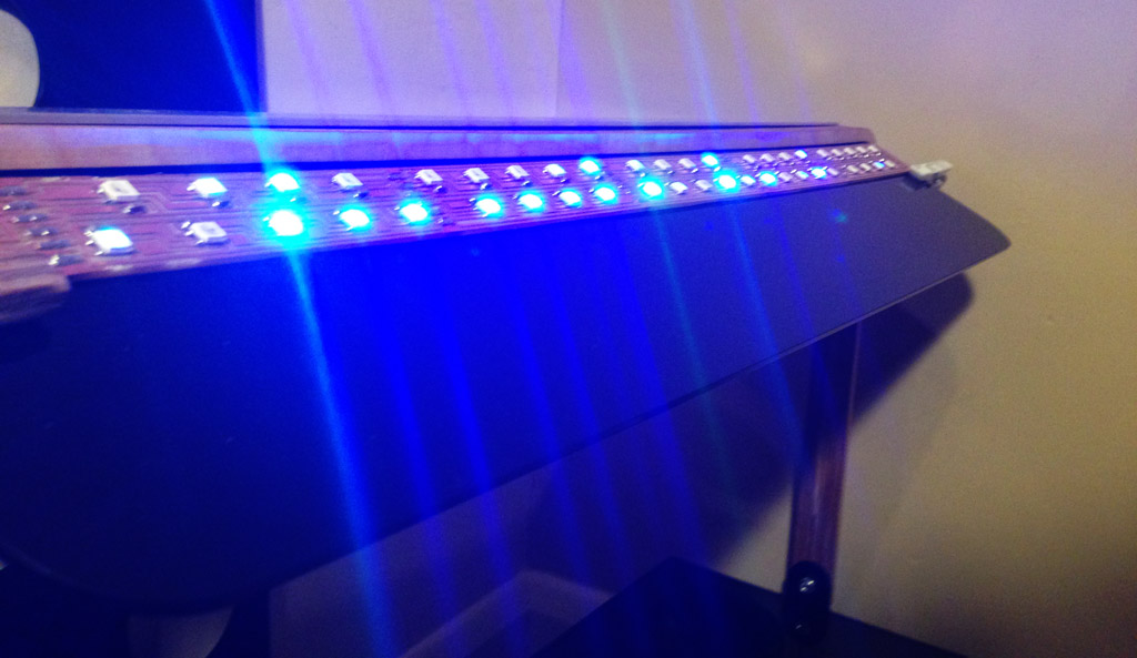
I checked the pin settings again, and decided I might have set incorrectly. I edited ws2812_config.h to port A, pin 7, recompiled the program and flashed the board.
Success!!!
 Disco, Disco, Disco!
The final thing to do was to write my own program to set the lights to the pink/purple colour I was after. I created a file called growbox.c in the Examples directory:
  #include <avr/io.h>
  #include "light_ws2812.h"

  #define PIX 45

  struct cRGB led[PIX];

  int main(void)
  {

      DDRB|=_BV(ws2812_pin);

    uint8_t i;
    for(i=0; i<PIX; i++)
    {
        led[i].r=255;led[i].g=0;led[i].b=128;
          ws2812_setleds(led,i);
    }
  }
Added the new file to the Makefile’s sources:
EXAMPLES = Rainbow, growbox
Compiled the code:
make -f Makefile
Uploaded the compiled code to the board:
avrdude -p t44 -P usb -c usbtiny -U flash:w:growbox.hex
 Perfect!
All that trouble, and the pin was set incorrectly.
Live. Learn… What’s next!?
Files
NeoPixel LED Module in Fritzing (31kB) - neopixel_module_9.fzz
Controller Traces (84kB) - growbox-controller_traces.png
Controller Drill (75kB) - growbox-controller_drill.png
Controller Cutout (52kB) - growbox-controller_cutout.png
Growbox Neopixel Arduino Sketch (929kB) - growbox_neopixel.ino
Final Growbox C Program (247 bytes) - growbox.c
TODOs
☑ Add an output device to a microcontroller board and program it to do something
☑ Describe the design / fabrication processes
☑ Explain the programming process and how the MCU datasheet helped
☑ Outline problems faced and how they were fixed
☑ Include design files and code
Links
Fab Academy 2016 - Output Devices
Chlorophyll - Wikipedia
SK6812 Neopixel LED Datasheet - 6812 LED Datasheet
Adafruit Neopixel Überguide - NeoPixel Überguide
Niklas Pöllönen - www.pollonen.com
Fritzing - fritzing.org
Adafruit NeoPixel Arduino Library - github.com
ATtinyCore Definitions for Arduino - github.com
Fuse Calculator - engbedded.com
Light WS2812 Library - github.com