Sorting out our Setup
Historically our Lab has had problems with getting the Roland MDX-20 talking to Fab Modules. The founding team of Aalto FabLab and Fab Academy alumni, Anu Määttä and Massimo Menichinelli, solved the problem back in 2012 using a Mac running Ubuntu, connected to the MDX-20 by a coupled USB-RS232-Serial cable (we’ll come back to why the cable is important soon).
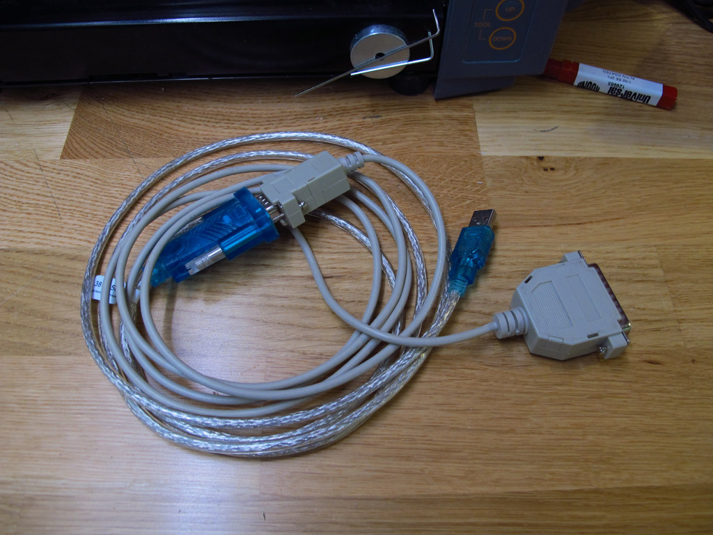 The USB-RS232-Serial cable that has been used in the Lab for the last 4 years
Unfortunately, that Mac’s hard drive is now kaput.
So, first things first, I needed to make a fresh Ubuntu installation on a different computer and set up Fab Modules. For the sake of variety, this time I choose to use a PC for the setup, and installed Ubuntu 14.04. Following the installation guide from the project’s GitHub repo was straight forward.
Once installed, I switched to the mod_server directory in terminal and ran the modules:
node mod_server.js
The server started and began listening for connections from 127.0.0.1 on 12345. From the Fab Modules website, I uploaded a .png file, selected .rml as the output format and PCB traces (1/64) for the process. From there, I could choose the MDX-20 from the machine dropdown and try sending a command.
I first wanted to try moving the spindle to x0 = 20, y0 = 20, z0 = 0. Sending the command with xyz0 threw the following error:
error: /bin/sh: 1: mod_serial.py: not founding
As described in the Fab Modules troubleshooting documentation, I checked that mod_serial.py was in the same folder as mod_server.js and prefixed the send command with ./
It’s alive!
Next, I cleaned up the MDX-20’s buildplate and lasercut a new acrylic spoilboard.
First Attempt
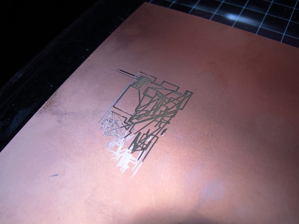 First (failed) attempt at milling the Fab ISP board with the MDX-20
There are two problems here - the toolpath is complete wrong compared to what was generated in Fab Modules, and also the difference in cut depth indicates that the surface of the spoilboard is not flat compared to the machine. After troubleshooting with Bas in Reykjavik, he recognised the erratic toolpath as a problem with data transfer between the computer and the MDX-20. Bas recommended to try to find the original serial-to-usb cable for the MDX-20, and also to use a PCB blank as a spoilboard to improve flatness.
Second Attempt
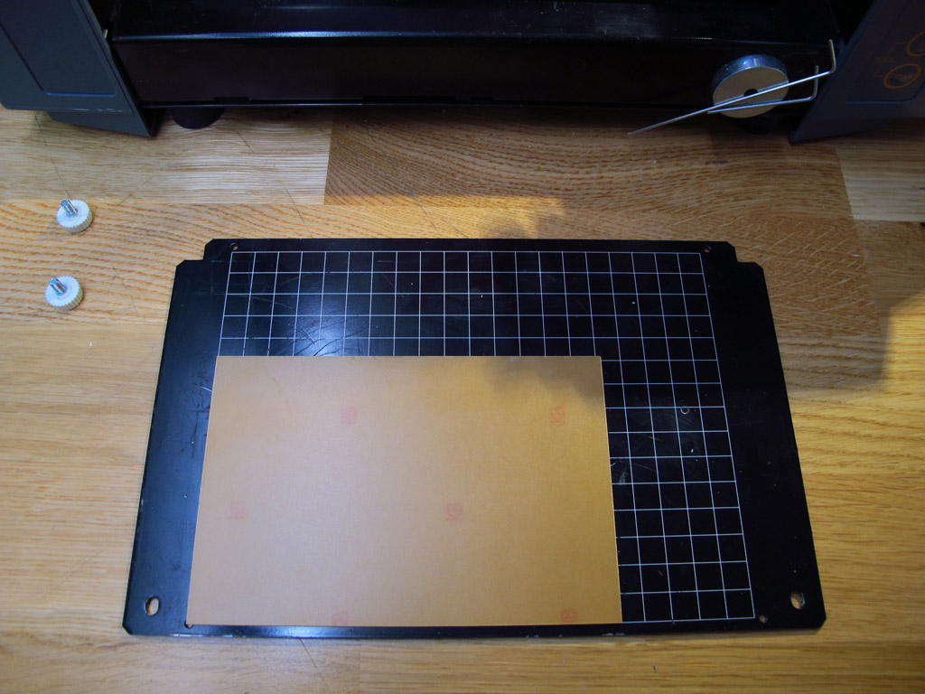 As per Bas’ recommendation, I swapped my acrylic spoilboard for an upturned PCB blank
 Milling the traces with 1/64” fishtail endmill
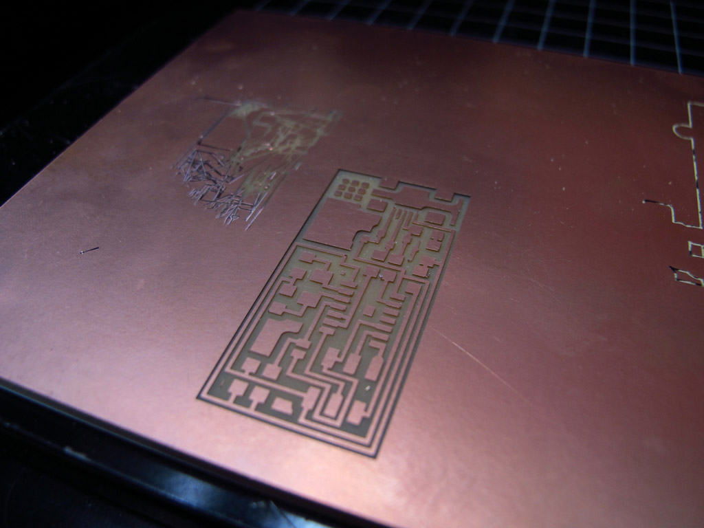 Traces cut cleanly, with no flatness issues this time at 0.1mm depth of cut
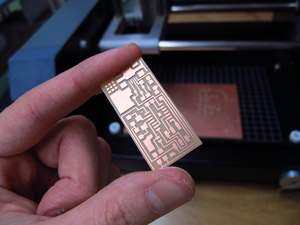 Board cutout in three passes using the 1/32” bit
Component stuffing
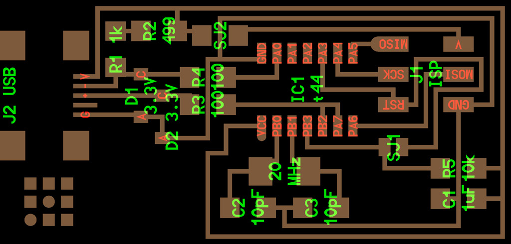 Hello ISP 44 schematic: http://academy.cba.mit.edu/classes/embedded_programming/hello.ISP.44.png
| Qty. | Component | Marking(s) |
|---|---|---|
| 1 | ATtiny44 | ICt44 |
| 1 | 6-Pin Header | J1 ISP |
| 1 | USB Mini-B SMD Connector | J2 USB |
| 1 | Crystal 20 MHz | 20 MHz |
| 1 | Capacitor 1uF | C1 |
| 2 | Capacitor 10pF | C2, C3 |
| 2 | Diode Zener 3.3V | D1, D2 |
| 1 | Resistor 1k ohm | R1 |
| 1 | Resistor 499 ohm | R2 |
| 2 | Resistor 100 ohm | R3, R4 |
| 1 | Resistor 10k ohm | R5 |
| 1 | Resistor 0 ohm | SJ2 |
Bill of materials (BOM) *SJ1 is a solder jumper - bridge with solder
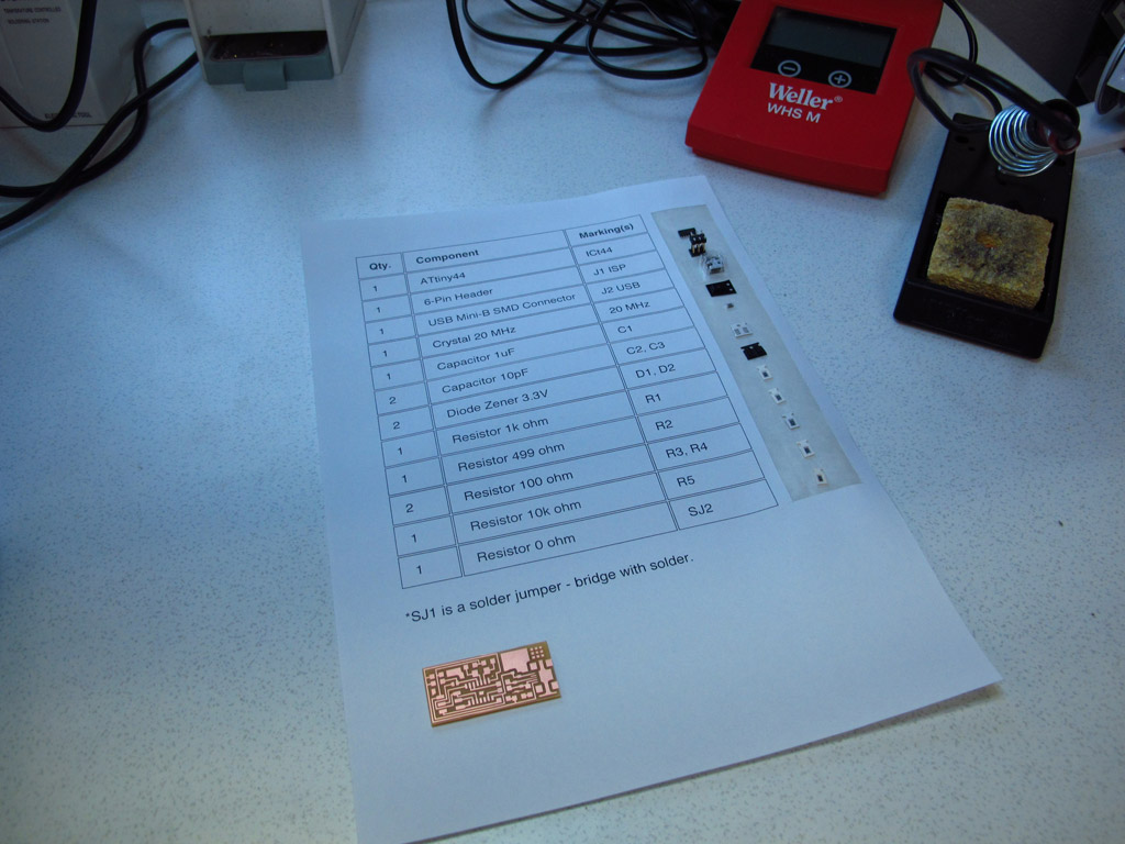 BOM print out with a panel of pre-spacing tape to help me pick the components
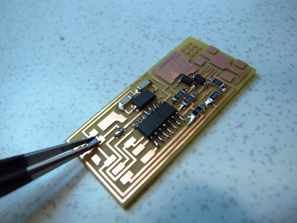 My first shot at soldering surface-mount components
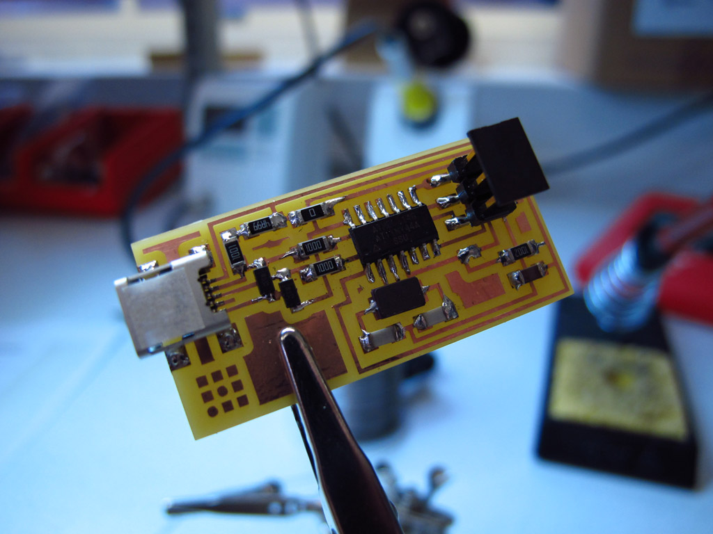 The board with all components mounted with shiny solder joints
Programming the ISP
Smoke test went without a hitch!
 Look mum, no smoke!
We had an Adafruit AVR Programmer kit in the Lab, it wasn’t built up, so I started putting it together. I completed the assembly apart from the 12.00 MHz ceramic oscillator which was missing from the kit! Since we didn’t have the correct spec through-mount oscillator in stock, I followed the Fab Academy tutorial for using an Arduino Uno as an ISP.
The Arduino sketch is included as an example in the Arduino IDE under:
File > Examples > ArduinoISP_
With the ISP board disconnected from the Arduino, upload the sketch.
The ArduinoISP sketch includes comments on how to connect the FabISP to the Arduino:
RST:      10
MOSI:     11
MISO:     12
SCK:      13
VCC is connected to 5V and GND to GND:
VCC:      5V
GND:      GND
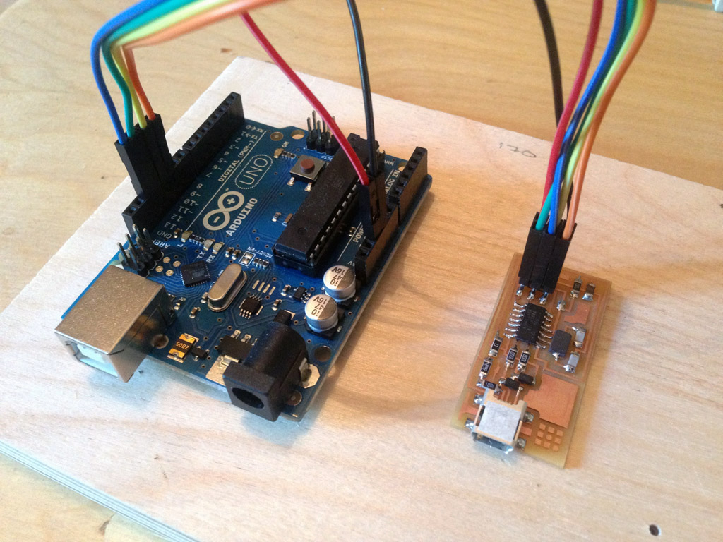 The FabISP connected to Arduino Uno
To send the Makefile to the FabISP, I first needed to install an AVR programming application. I’m running Mac OS, so I chose Crosspack AVR.
I downloaded the FabISP Firmware from the Fab Academy documentation, and edited the programmer configuration in the Makefile to:
AVRDUDE = avrdude -c stk500v1 -b19200 -P /dev/tty.usbmodem1411 -p $(DEVICE)
Now to compile the firmware:
cd Downloads/fabISP_mac.0.8.2_firmware
make clean
A positive response should be:
rm -f main.hex main.lst main.obj main.cof main.list main.map main.eep.hex main.elf *.o usbdrv/*.o main.s usbdrv/oddebug.s usbdrv/usbdrv.s
Now compile:
make hex
Response:
avr-gcc -Wall -Os -DF_CPU=20000000     -Iusbdrv -I. -DDEBUG_LEVEL=0 -mmcu=attiny44 -c usbdrv/usbdrv.c -o usbdrv/usbdrv.o
avr-gcc -Wall -Os -DF_CPU=20000000     -Iusbdrv -I. -DDEBUG_LEVEL=0 -mmcu=attiny44 -x assembler-with-cpp -c usbdrv/usbdrvasm.S -o usbdrv/usbdrvasm.o
avr-gcc -Wall -Os -DF_CPU=20000000     -Iusbdrv -I. -DDEBUG_LEVEL=0 -mmcu=attiny44 -c usbdrv/oddebug.c -o usbdrv/oddebug.o
avr-gcc -Wall -Os -DF_CPU=20000000     -Iusbdrv -I. -DDEBUG_LEVEL=0 -mmcu=attiny44 -c main.c -o main.o
main.c:88:13: warning: always_inline function might not be inlinable [-Wattributes]
 static void delay ( void )
             ^
avr-gcc -Wall -Os -DF_CPU=20000000     -Iusbdrv -I. -DDEBUG_LEVEL=0 -mmcu=attiny44 -o main.elf usbdrv/usbdrv.o usbdrv/usbdrvasm.o usbdrv/oddebug.o main.o
rm -f main.hex main.eep.hex
avr-objcopy -j .text -j .data -O ihex main.elf main.hex
avr-size main.hex
   text       data        bss        dec        hex    filename
      0       2002          0       2002        7d2    main.hex
Next, set the fuses so the board will use the external crystal:
make fuse
Response:
avrdude -c stk500v1 -b19200 -P /dev/tty.usbmodem1411 -p attiny44 -U hfuse:w:0xDF:m -U lfuse:w:0xFF:m

avrdude: stk500_getparm(): (a) protocol error, expect=0x14, resp=0x14

avrdude: stk500_getparm(): (a) protocol error, expect=0x14, resp=0x01
avrdude: stk500_initialize(): (a) protocol error, expect=0x14, resp=0x10
avrdude: initialization failed, rc=-1
         Double check connections and try again, or use -F to override
         this check.

avrdude: stk500_disable(): unknown response=0x12

avrdude done.  Thank you.

make: *** [fuse] Error 1
Oh dear. At this point, I inspected the board closely for cold joints or visible shorts and realised I hadn’t soldered the pins on the back of the USB header at all! I also had a 4.99 Ohm resistor in place of the 499 Ohm resistor. Lesson learned: don’t trust that resistors have been put in the correct draw in the component tower - always check the component markings.
With those problems fixed, I attempted to set the fuses again (this time using sudo to run my command):
sudo make fuse
Still I had the same error message, even after checking carefully for shorts with a multimeter, so I abandoned the Arduino and tried using a FabISP made by Ali Neissi.
I changed the programmer config to:
AVRDUDE = avrdude -c usbtiny -p $(DEVICE)
Then ran:
sudo make fuse
Response:
avrdude -c usbtiny -p attiny44  -U hfuse:w:0xDF:m -U lfuse:w:0xFF:m

avrdude: AVR device initialized and ready to accept instructions

Reading | ################################################## | 100% 0.00s

avrdude: Device signature = 0x1e9207
avrdude: reading input file "0xDF"
avrdude: writing hfuse (1 bytes):

Writing | ################################################## | 100% 0.00s

avrdude: 1 bytes of hfuse written
avrdude: verifying hfuse memory against 0xDF:
avrdude: load data hfuse data from input file 0xDF:
avrdude: input file 0xDF contains 1 bytes
avrdude: reading on-chip hfuse data:

Reading | ################################################## | 100% 0.00s

avrdude: verifying ...
avrdude: 1 bytes of hfuse verified
avrdude: reading input file "0xFF"
avrdude: writing lfuse (1 bytes):

Writing | ################################################## | 100% 0.00s

avrdude: 1 bytes of lfuse written
avrdude: verifying lfuse memory against 0xFF:
avrdude: load data lfuse data from input file 0xFF:
avrdude: input file 0xFF contains 1 bytes
avrdude: reading on-chip lfuse data:

Reading | ################################################## | 100% 0.00s

avrdude: verifying ...
avrdude: 1 bytes of lfuse verified

avrdude: safemode: Fuses OK (H:FF, E:DF, L:FF)

avrdude done.  Thank you.
That’s more like it!
sudo make program
Response:
avrdude -c usbtiny -p attiny44  -U flash:w:main.hex:i

avrdude: AVR device initialized and ready to accept instructions

Reading | ################################################## | 100% 0.00s

avrdude: Device signature = 0x1e9207
avrdude: NOTE: "flash" memory has been specified, an erase cycle will be performed
     To disable this feature, specify the -D option.
avrdude: erasing chip
avrdude: reading input file "main.hex"
avrdude: writing flash (2002 bytes):

Writing | ################################################## | 100% 1.96s

avrdude: 2002 bytes of flash written
avrdude: verifying flash memory against main.hex:
avrdude: load data flash data from input file main.hex:
avrdude: input file main.hex contains 2002 bytes
avrdude: reading on-chip flash data:

Reading | ################################################## | 100% 2.32s

avrdude: verifying ...
avrdude: 2002 bytes of flash verified

avrdude: safemode: Fuses OK (H:FF, E:DF, L:FF)

avrdude done.  Thank you.

avrdude -c usbtiny -p attiny44  -U hfuse:w:0xDF:m -U lfuse:w:0xFF:m

avrdude: AVR device initialized and ready to accept instructions

Reading | ################################################## | 100% 0.00s

avrdude: Device signature = 0x1e9207
avrdude: reading input file "0xDF"
avrdude: writing hfuse (1 bytes):

Writing | ################################################## | 100% 0.00s

avrdude: 1 bytes of hfuse written
avrdude: verifying hfuse memory against 0xDF:
avrdude: load data hfuse data from input file 0xDF:
avrdude: input file 0xDF contains 1 bytes
avrdude: reading on-chip hfuse data:

Reading | ################################################## | 100% 0.00s

avrdude: verifying ...
avrdude: 1 bytes of hfuse verified
avrdude: reading input file "0xFF"
avrdude: writing lfuse (1 bytes):

Writing | ################################################## | 100% 0.00s

avrdude: 1 bytes of lfuse written
avrdude: verifying lfuse memory against 0xFF:
avrdude: load data lfuse data from input file 0xFF:
avrdude: input file 0xFF contains 1 bytes
avrdude: reading on-chip lfuse data:

Reading | ################################################## | 100% 0.00s

avrdude: verifying ...
avrdude: 1 bytes of lfuse verified

avrdude: safemode: Fuses OK (H:FF, E:DF, L:FF)

avrdude done.  Thank you.
Yiiihewwww! With that, I verified that the FabISP was identified correctly.
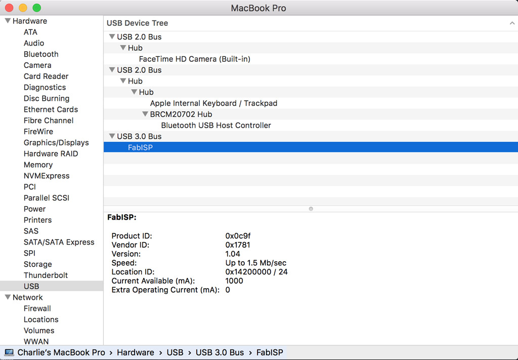 The FabISP making friends with my Macbook
All good! Finally I desoldered jumpers SJ1 and SJ2, then went for a beer!
 The FabISP completed, programmed and ready to save the day
Files
FabISP Traces (14kB) - hello-ISP44_traces.png
FabISP Cutout (12kB) - hello-ISP44_interior.png
TODOs
☑ Make the Fab ISP
☑ Program the board
☑ Explain problems and how they were overcome
☑ Include a ‘hero shot’ of the board
Links
Fab Academy 2016 - Electronics Production
FabISP Programming Tutorial - FabISP: Programming
FabISP Troubleshooting - FabISP: Electronics Production