For a while now, I have been planning to build myself a mini-longboard to make the repetitive journeys up and down the Media Factory corridor more fun, whilst simultaneously increasing the risk of shin injuries for our visitors!
The plan would be to make something like a Penny Board, but from plywood instead of plastic, and with a laser-engraved pattern on the deck.
Here’s how the Pikku-Pitkäboard (Little-Longboard in Fin-glish) finally came together!
Shaping the Board
As I mentioned before, this project has been on my todo list for a while. I had actually already modeled the shape of the board using Onshape (a cloud-based solid modeling application from the people who made SolidWorks).
I was given beta access by a friend, but I never seemed to have enough time to get into it properly. I used the Pikku-Pitkäboard as an excuse to try it out.
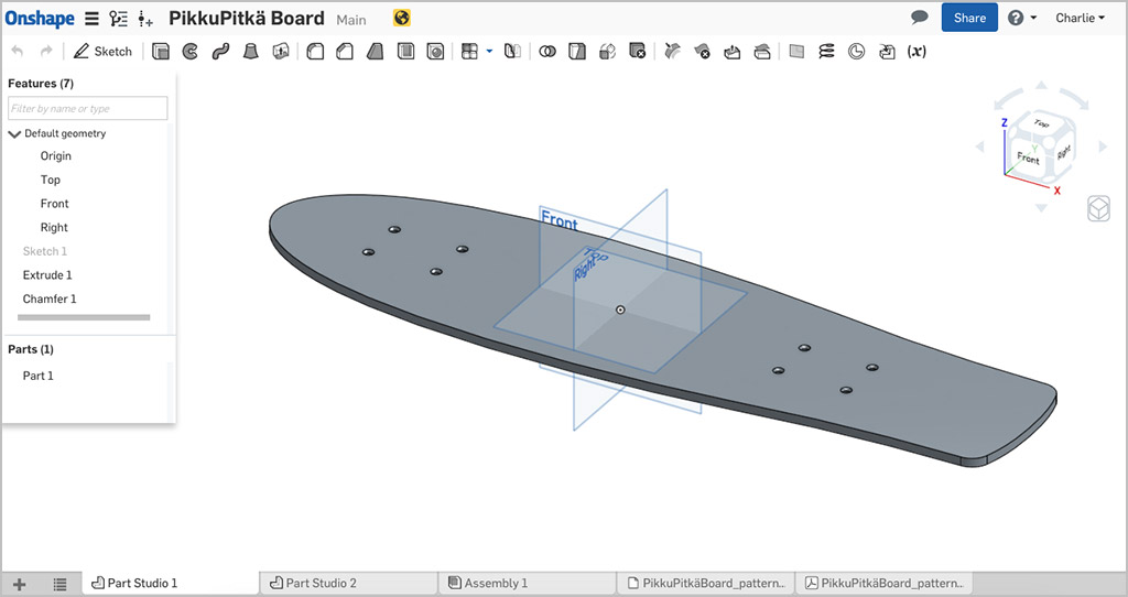 The Pikku-Pitkäboard in Onshape with illustrator and pdf design files attached
Three good things about Onshape:
- It’s free for individuals, hobbyists and makers to use with up to 10 private documents and unlimited public documents (which is perfect for Fab Labs!)
- Project documents and files can be added to projects in tabs, so your design files and documentation can exist together in one place.
- Cloud-based CAD means that you will always be using the latest release of the software (less updating packages on Lab computers)
One major downside to cloud-based modeling though is that it can be dreadfully slow at times!
Planning the Job
With CNC work it’s good to have a game plan for processes, workholding, tooling, etc. before you get too far into the setup.
So here’s my plan:
- Clamp the workpiece on the T-track table with a spoilboard below.
- Drill the boltholes for the longboard trucks with a 5mm twist drill.
- Use the boltholes to screw the workpiece to the spoilboard below.
- Cut the outer profile, full depth with a 6mm straight-cut, 2-flute endmill.
- Cut registration marks to help alignment during the laser-engraving process.
Nothing too fancy, but adding those hold-down screws allows me to cutout the full profile without the need for tabs or bridges, saving me time on finishing and money on sandpaper!
Preparing the Cutting Files
From Onshape, I downloaded a DXF from the sketch of the deck and imported that into Rhino, then:
- Checked the overall dimensions (the BoundingBox command is very helpful).
- Separated the geometry onto layers for drill holes and cutouts.
- Created a rectangle to match my stock material dimensions (I found an offcut of 12mm birch ply that was perfect for the job), and positioned it’s lower-left corner at the origin.
- Located the board geometry within the material bounds.
- Create additional lines as references for the engraving process.
Setting up the Toolpaths
Now that I had the cutting files sorted, it was time to generate the toolpaths. Our large CNC mill is set up with Surfcam. I’m not a big fan of Surfcam to say the least, and have been trying out Autodesk Fusion 360 with their integrated HSM Works CAM engine. With the help of one of our community members, Jason from Showerloop, we’ve been working with the guys at Autodesk to perfect a post-processor for our machine. It’s looking very promising!
I didn’t have a lot of time to get this job done, so for speed and familiarity, I fired up Surfcam.
 Setting up Drill Proccesses in Surfcam
Drill Process
- 5mm Twist Drill from our beautiful Fisch wood drill set
- 2000rpm Spindle Speed
- Peck cycle, with 5mm increment
- 15mm depth to tip (slight overrun into the spoilboard)
Outer Contour
For the contour cuts, I chose a straight-flute endmill. Since I’m cutting plywood, the top surface has a tendency to splinter when cutting across the grain using an up-spiral cutter. The straight-flute endmill should shear the plywood with each cut and reduce the tear out.
- 6mm Straight-Flute Endmill
- 16000rpm Spindle Speed
- 1400 mm/min Feedrate, 200 mm/min Plungerate
- 13mm cut depth, 3.25mm stepdown
- Climb cutting
Registration Marks
- 6mm Straight-Flute Endmill
- 16000rpm Spindle Speed
- 1400 mm/min Feedrate, 200 mm/min Plungerate
- 13mm cut depth (from top of stock, so 1mm into the spoilboard), 13mm stepdown
- Conventional cutting (to get the cut on the correct side of the line)
 The toolpaths for drill-holes, outer contour and registration marks set in Surfcam
 Always, always preview your toolpaths before moving to cutting
Setting up the Job
The setup for CNC work can be time consuming, but it’s also quite fun (if you like this sort of thing).
 The workpiece clamped on all four corners with T-track clamps, MDF spoilboard below
 Aligning a straight edge of the workpiece to the machine’s X-axis, zeroing in X and Y
 5mm drill already in, zeroing in Z with the mobile calibrator
Running the Job
At the time of writing, it seems I have made a most unfortunate error and deleted my process shots for running the CNC job and setting up for laser engraving…
Aaarrgghh!!!
Here’s how it went in words:
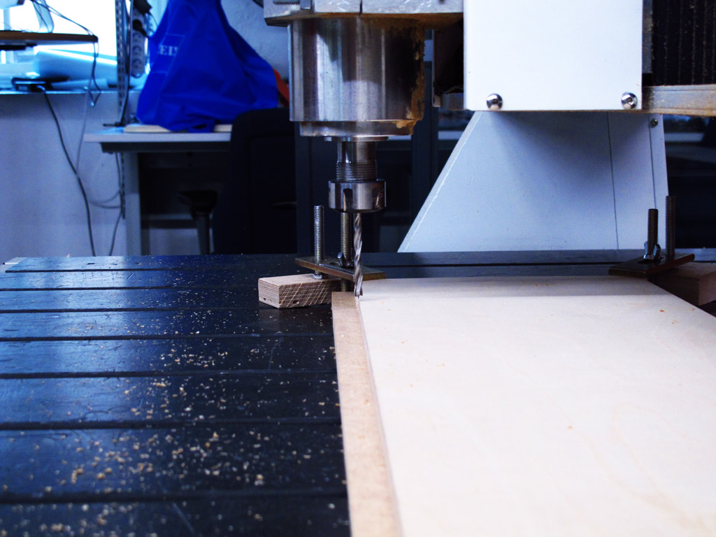
- With the workpiece clamped, origin set and Z-axis zeroed, I ran the drill processes to make the 8 boltholes which would eventually fasten the trucks to the deck.
- Using woodscrews and scrap pieces of wood as washers, I fastened the workpiece to the spoilboard through the newly formed boltholes.
- Next, I switched the drill bit for the straight-flute endmill, re-calibrated the Z-axis offset, and ran the deck contour cut.
- I then released one clamp, moved it off the workpiece and clamped it down again on the spoil board, and repeated until all the clamps were holding the spoilboard instead of the workpiece. This allowed me to remove the excess material without moving the workpiece, before:
- Running the registration mark cuts.
With all the CNC work now completed, I cleaned up and moved over to the lasercutter (deck still attached to the spoilboard). Alignment is critical at this stage, so using the laser’s dot pointer, I moved the carriage back and forth along the X-axis and adjusted the deck and jig until I had it aligned to the registration marks. The the Y-axis aligned, I could move the carriage to the left corner of the registration mark and set the Home position.
 Engrave pattern for the deck
I loaded the artwork I had made for the engraving into the computer driving the lasercutter and set the engrave settings:
- Job type : Raster
- Resolution : 300dpi (reasonable quality, but faster than 600dpi)
- Speed : 70
- Power : 70
Time to set the focus to the top surface and let it rip!
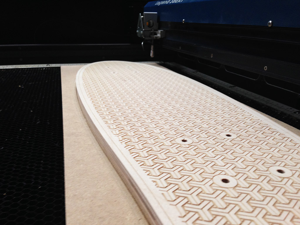 View along the deck after engraving
 Close-up of the engraved pattern
Problems and Solutions
Strangely, the curve at the nose of the deck was faceted rather than smooth. I put this down to the dxf export from OnShape which seems to simplify curves in some instances. Playing with the export options and file formats should solve the problem in the future, but for now a few passes with some sandpaper will do the trick.
The registration marks worked well for aligning the laser engraving, but there was a very slight <1mm misalignment noticeable around the boltholes (not a big deal). If I was going to make more boards, I would spend some time to build a permanent fixture and save workpiece offsets in the machines.
The engrave pattern cause a few problems as well. Originally, I tried sending a pdf to the lasercutter, but there was so much data that it crashed Corel Draw. The answer was to use the Illustrator file with the pattern expanded and shapes combined.
Putting it Together
Time to put wheels on this badboy! I ordered most of the hardware from SkatePro.com, plus 8 countersunk M5 socket bolts from local hardware goldmine Ruuvi Säve.

| Qty. | Item | Price (EUR) |
|---|---|---|
| 1 | Penny Nickel 4” truck set | 39,95 |
| 1 | Globe Bantam marbled wheels (59mm) | 37,95 |
| 1 | Hydroponic ABEX 3 bearings | 12,95 |
| 8 | M5x30 countersunk socket bolks blk | 2,00 |
| - | Total | 92,85 |
Files
Rhino File (34kB) - PikkuPitkaBoard_2d.3dm
Engrave Pattern (915kB) - PikkuPitkaBoard_pattern.ai
Surfcam File (27kB) - pikkuboard.scprt
TODOs
☑ Make something big on a CNC machine
☑ Explain how the files for machining were made
☑ Show how the object was made
☑ Describe problems and solutions
☑ Include original design files and a hero shot
Links
Fab Academy 2016 - Computer-Controlled Machining