
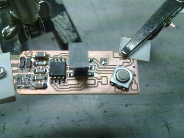
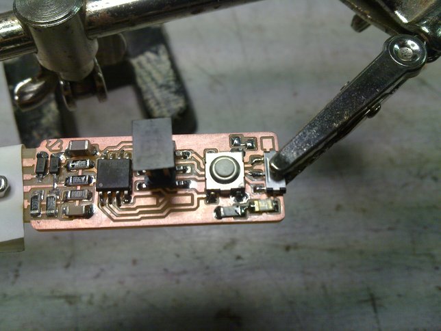
The new board clamped into a "third-hand", this will stop it from moving around while we solder. The pieces of paper are there to prevent unnesecary scratching from the clips.
The needed components in the order we'll be using them:
| Part | Value | Package | |
|---|---|---|---|
| inventory | ideal | ||
| R1 | 1 Kilo-Ohm | 2.2 Kilo-Ohm | SMD-1206 |
| R2 | 1 Kilo-Ohm | SMD-1206 | |
| D1 | 3.3-Volt Zener | 3.6-Volt Zener | SMD-SOD123 |
| D2 | 3.3-Volt Zener | 3.6-Volt Zener | SMD-SOD123 |
| C1 | 10 micro-Farad | SMD-1206 | |
| R3 | 49 Ohm | 68 Ohm | SMD-1206 |
| R4 | 49 Ohm | 68 Ohm | SMD-1206 |
| R7* | 0 Ohm | PTC 0.5 Ampere | SMD-1206 |
| C2 | 100 nano-Farad | SMD-1206 | |
| IC1 | ATTiny45 | ATTiny85 | SMD-SOIC8 |
| JP1 | 2x6 ISP | 2x8 header | SMD pinheader |
| S2 | B3SN-3112 | SMD tactile switch | |
| S1 | AYZ0102AGRLC | SMD slide switch | |
| R5 | 1 Kilo-Ohm | SMD-1206 | |
| LED1 | red LED | SMD-1206 | |
| R6 | 499 Ohm | 470 Ohm | SMD-1206 |
| LED2 | green LED | SMD-1206 | |
The new board clamped into a "third-hand", this will stop it from moving around while we solder.
The pieces of paper are there to prevent unnesecary scratching from the clips.
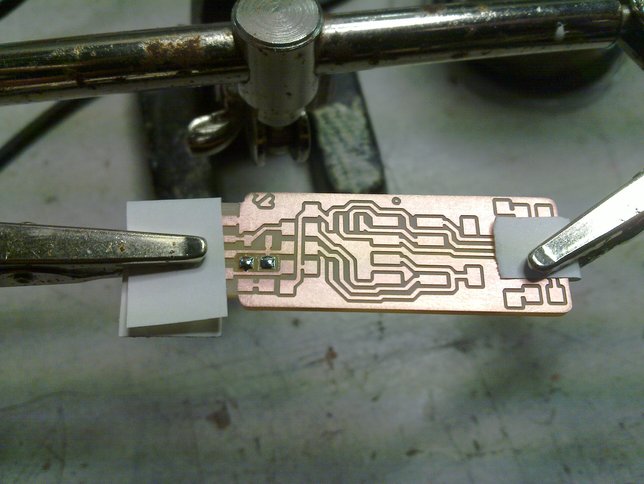
We'll start with two 1K resistors, here are a couple of solder blobs on one side of their pads.

The two resistors dropped into the solder, effectively glueing them in place.
The resistors soldered on both sides. Tinned the pads for the next two components, the 3V3 zener diodes.
These are a bit more tricky as the "legs" are smaller.
Note that diodes (unlike resistors) have an orientation, usually indicated by a line on the package.
In this case the side with the line should be towards the bottom of the picture (or the middle of the board).

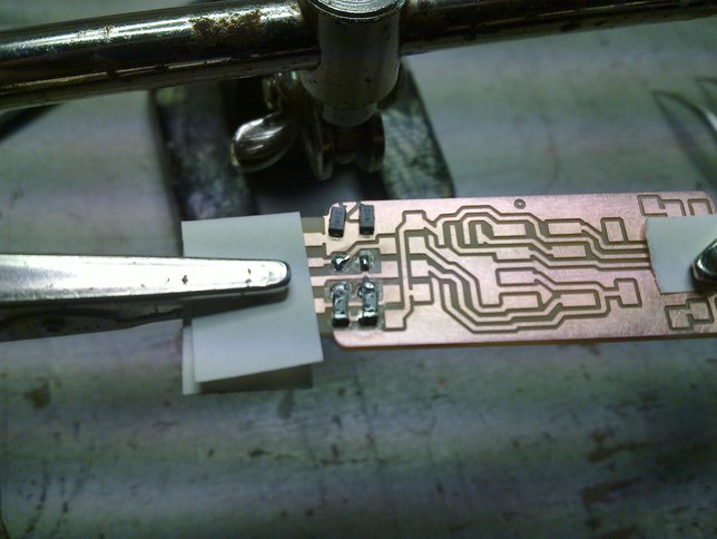
The zener diodes glued into place by dropping them in the solder. Good practice for the upcomming microcontroller which has 8 similar legs but closer together.
Zener diodes soldered, tin on the pads for the 10 uF capacitor, two 49.9 Ohm resistors, a 0 Ohm resistor and the 100 nF capacitor (from top to bottom).
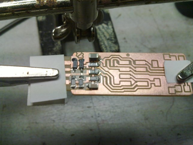
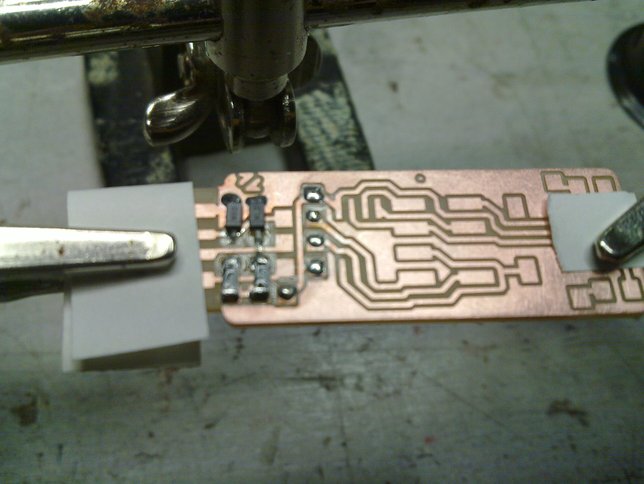
The components solder-glued in place.

And soldered on both sides.
The first pad of the ATTiny45 tinned.

The ATTiny45 solder-glued into place.
Note the dot in the left bottom corner of the IC indicating pin 1, like with the diodes, this component should not be soldered on the other way around.
Make sure that all the legs rest on the pads where they belong, check this with a loupe.
Then solder the other legs and finally (re-)do the first one.

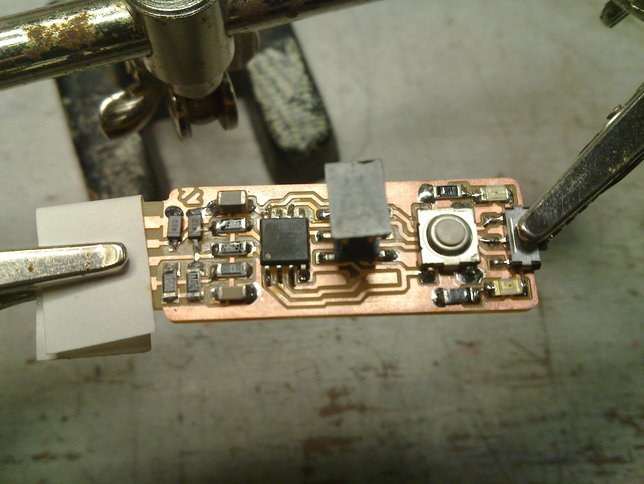
ATTiny soldered in place, first pad tinned for the ISP connector. There are two extra pads at the bottom that aren't used in this particular application.
ISP connector soldered in place, note the two unused pads.
One pad tinned for the reset button.
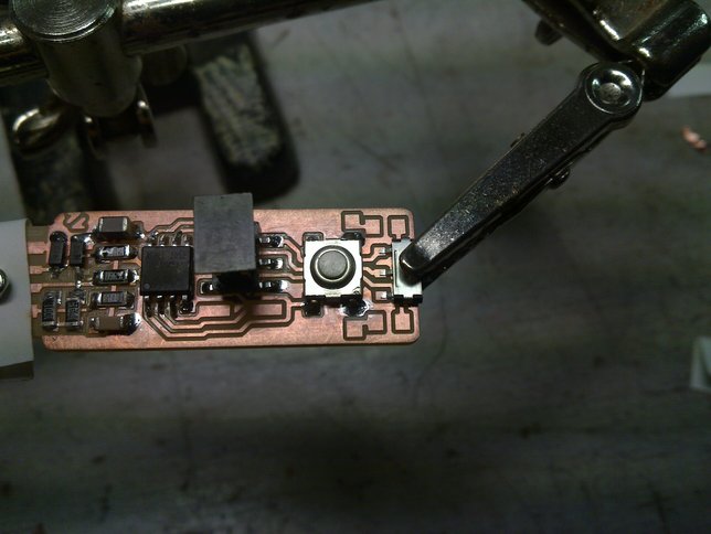
Reset button soldered, power switch put into place.
The power switch is the only component that we don't have to glue on with solder first, as the two notches on the back fit into the holes, keeping it in place already.
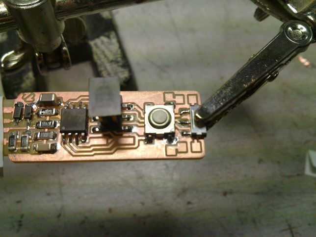
So just solder it on right away.
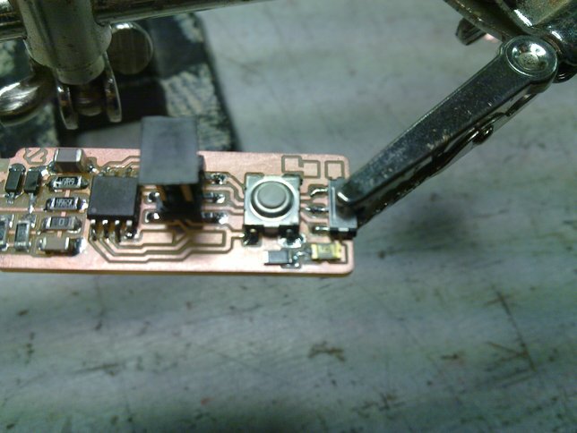
The green LED plus it's 499 Ohm resistor glued into place. Note that a LED (Light Emitting Diode) is also a (special kind of) diode, and the little green line should be on the left.
The green LED plus resistor soldered into place.
Solder on the pads for the red LED and it's 1K resistor.

The red LED and it's resistor glued in place.
The little green line of the LED should be on the left again.
Everything soldered, so now we can take it out of the "third hand".
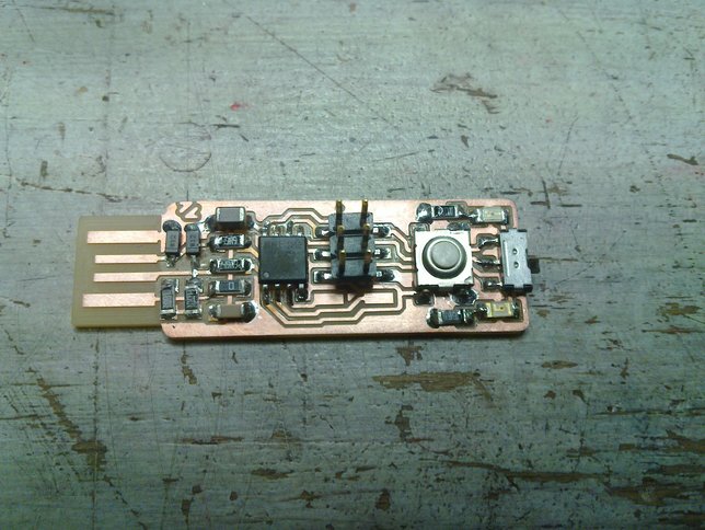
The end result all stuffed, ready for cleaning and testing.
You can just wash the board with water and soap again, or use a solvent like isopropanol, to take the remaining flux and whatever off. Just make sure it has dried properly before moving on.
After a visual inspection to see that all the solder joints are nice and shiny, it is recommended to test the connections with a multimeter. It takes a few minutes, but can save you from a lot of hassle before you run into trouble.
[TODO: INSERT VIDEO]