Final Project Notes and Process
Process and notes
Overall Strategy
For my final project I used the Satshakit Arduino clone as the microcontroller. The biggest advantage was that there is a lot of code and libraries already out there to run input and output devices. Another benefit to using an Arduino clone was that I could test the code on a Arduino that I knew worked, thus was able to separate hardware problems from software problems. My first task was then to get the ultrasonic input and LCD output working on an Arduino and then it should transfer directly to the Satshakit Arduino clone.
Making the Arduino Clone
I first made the FABkit Arduino click here that used the same ATmega 328 chip as an Arduino and thus should be Arduino compatible. To the get the board to cut out on the Othermill required a massive amount of redesign because it was originally designed to be cut on a laser cutter. All of the traces coming from the bottom of pins touched when I first milled it out. I have posted a version that cuts on a the Othermill.
I was unable to program the FABkit Arduino because the newer versions of the Arduino program no longer has a "boards.txt" file, which you need to add a custom board. To see a discussion of this problem click here . Even on older Mac versions of Arduino I could not find this file. I did eventually get the FABkit added to the board list using an older PC version of Arduino but I still have not had a chance to see if it will actually boot load the FABkit. The reason is that while I was working on getting the FABkit to program the Satshakit Arduino clone was released. click here . This board has many advantages, namely you do not need to add a custom board to the Arduino and the pin numbers are the same, so it is truly an Arduino compatible board.
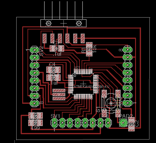
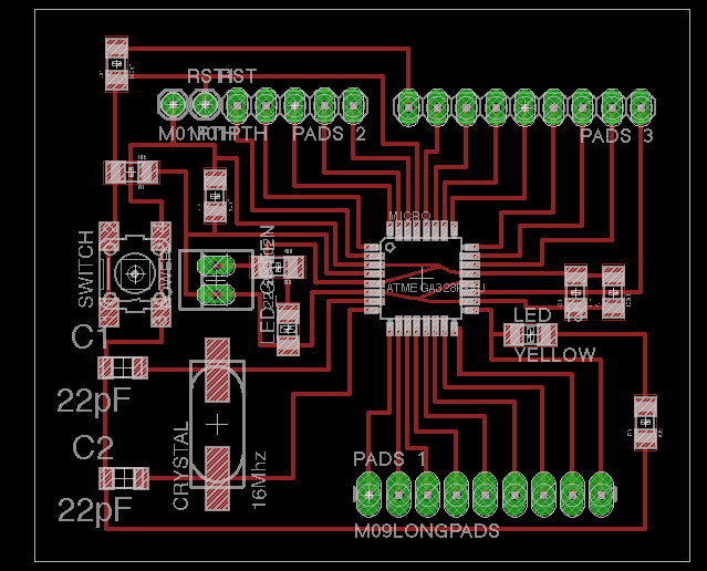
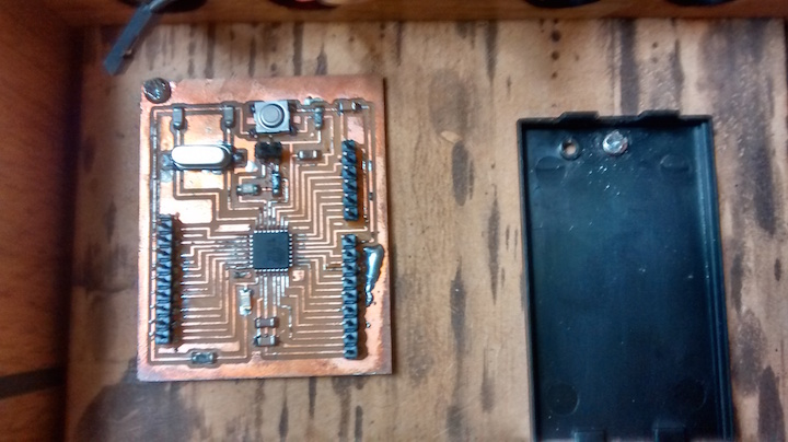
I made two different versions of the Satshakit Arduino. The first one was the same as the original design with a couple of fixes to enable them to mill better on the Othermill. One of the lines going through the capacitors on the right side of the board was not centered and you could see in the tool path of OtherPLan that it would not cut. I fixed this error by centering the line through the tool path.
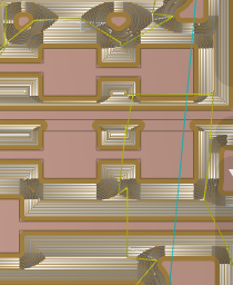
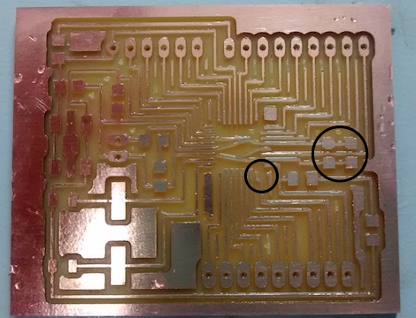
The other problem was more odd because it did not show up on the projected tool path. For some reason the Othermill consistently cut a gap in one of the pads for the chip. Oddly it did not show this gap in the preview tool path in Otherplan which is generally pretty good at finding errors. This makes me think it was some error in the tool path of the Otherplan program. Because the bad cut was happening at the end of row of pads it was easy to fix by moving the trace over, the assumption being that by forcing the Othermill to take a different tool path would get rid of the bug. Below is the board that I cut with the fix to both of these problems
The addition of a second ground pin was a change I made to my subsequent Arduino boards. I placed it next to the reset pin.
For the shematic file click here. For the .brd file click here.
In theory boot loading the satshakit should have been simple since you can boot load it as standard Arduino Uno. We first tried to use a standard Ardunio Uno as a programmer. Directions on how to do this are click here . However we were having huge problems when we tried to boot load it. Every time we tried we got an error message saying that it was out of sync. At this point we did not know if we were doing something wrong in our programing or if our soldering was bad. I really did not think it was the soldering because it looked good and I checked every pin for shorts and could find none.
After doing some research on how to program ATmega 328 chips I found that many people had similar problems with the other 328 chips but not the Atmega 329p-AU that we were using. I also found that you only need relatively few parts to load the boot loader. You only need the chip, the crystal with its capacitors and a resistor for the reset pin. click here . So I decided make another board with only components so as to eliminate the soldering factor as much as possible. Much to my frustration the mimimum component board still got the same error message.
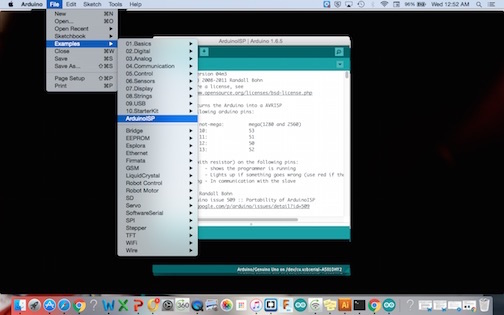
I felt pretty confident at this point that the soldering was not the problem. Finally it took our Fab Guru Terence to come and figure out the problem. He checked the boards and sure enough he could not find a problem with the soldering. He then realized that we I was not first uploading sketch for the Arduino as ISP. Looking back all the directions say to do this but I was so focused on getting the wiring correct that I didn’t notice it. I think part of the confusion was also that I thought that running the ISP sketch for the Arduino was what you did when you selected under tools to have the Arduino act as an ISP.
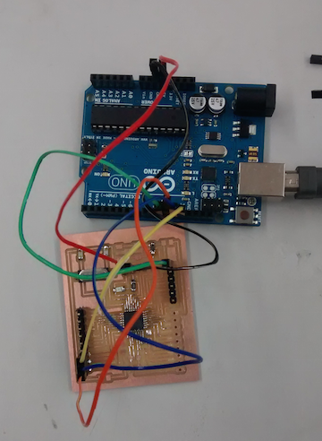
Once we figured this out, all the boards we made easily bootloaded and we were able to program them using the standard directions click here. Below is a picture of an Arduino clone being programed using an Arduino as an ISP.
Programing the Satshakit board
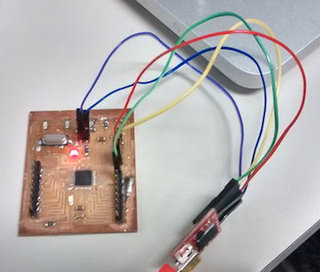
Once we got the board boot loaded, programing was a very straight forward process. To see the hookup for programing the Satshakit click here .
Just as a simple test I selected the blink program to see if the Satshakit was working properly. It gave me an error message the first time. Then I realized the port was not selected. Oddly the port for the USB was not even an option. I unplugged the USB and then the port was an option again. This is a problem a lot of people seem to be having. One theory is that if you have multiple versions of Arduino loaded it causes conflict between the two versions of Arduino. In any case I was eventually able to install the blink program.
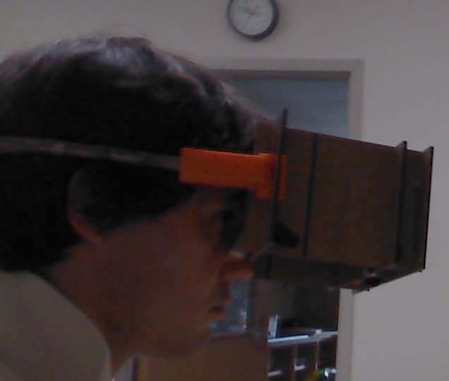
If you’re wondering, that is my lab partner Tom in the background extoling the virtues of making an Arduino clone. He is correct in that as you will see in the subsequent documentation, being able to trouble shoot code using an actual Arduino is a huge advantage because it takes out the variable of the board design.
Output LCD
I used the Sparkfun LCD screen that was Serial Enabled click here along with the sparkfun LCD Backpack click here . The advantage to using the LCD backpack was that it reduces the number of wires to just three: Power, Ground and input. I wanted to just see if I could get the LCD screen to display data. The sparkfun site has a good tutorial that has Arduino for generating random data click here . I hooked up the LCD screen and uploaded the program. Success! Now to move on to the input.
Input: Ultrasonic sensor
Next I wanted to get the ultrasonic sensor working on an Arduino. I found some code for the SR-HC04 sensor and uploaded it to the Arduino. When I tried to get it to come up on the serial monitor it did not work. One thing that I really like about this code is that if the Arduino is not getting a signal it returns a value of -1, which is exactly what happened. I tried a different ground pin on the Arduino and then it started to give me values.
I next worked on getting the ultrasonic sensors working with the Arduino. The code uploaded easily. However when I went to see if the sensor was working I got nothing on the serial monitor, not even a negative one. Then I realized that I had unplugged the TX and RX wires on the Arduino clone that go to the FTDI basic. These wire are obviously not needed when using a regular Arduino because its hooked up via a USB cable but since the Satshakit must get its power from a FTDI cable then both the transfer and receive wires must also be hooked up. Once I did this it worked great.
Getting the ultrasonic sensor and LCD screen to work together
The key task here was to combine the code for the ultrasonic sensor with the LCD and in addition add a second sensor.
The need to add a myserial to the code may seem odd when there is already serial command in the LCD code. It is necessary because the variables for the serial command must be defined differently for the LCD screen. As such the serial output to the LCD screen must be given a different name so that the chip knows to send the serial output to pin 2 as defined in the code.
The next thing was to define the pins for the second set of sensors.
// defines pins numbers, added
#define leftechoPin 7 // Echo Pin
#define lefttrigPin 8 // Trigger Pin
#define rightechoPin 9 // Echo Pin
#define righttrigPin 10 // Trigger Pin
#define LEDPin 13 // Onboard LED
The next pin modes for the left and right pins were added
pinMode(leftTrigPin, OUTPUT);
pinMode(leftEchoPin, INPUT);
pinMode(rightTrigPin, OUTPUT);
pinMode(rightEchoPin, INPUT);
Following this the code was copied from the Sparkfun code for data but modified such that temp and rmp were replaced with left and right
to download the code for using two ultrasonic sensors with an LCD output click here.
I was very excited when this code worked. The one thing that was weird about the code was that it would not present the serial print on the LCD screen for left and right. It would make more sense however if it never worked but it did work on some occasions. My suspicion is that the ultrasonic sensors may be interfering with the LCD screen because when the ultrasonic sensors are not hooked up the left and right appeared on the LCD screen more often. As can be seen in the video the right and left is coming up on the LCD but for some reason it stopped working even though nothing changed in the setup. In any case it would be nice to have the left and right designated it is not essential
Making the Goggles
Originally I was thinking about making my goggles out of folded cardboard. I played around with Fusion360. Mostly I wanted to try making a 3D model of the folded cardboard in Fusion 360 so that I could model how the goggles would be assembled. I decided to start out by making my goggles. In doing this I realized that it is not possible to do this in Fusion 360 but rather must be done in a program like RHINO, which I do not have.
Ultimately I decided folding the cardboard was not the best way to make the goggles. I realized that it would be a lot easier to make the goggles by interlocking pieces. I started by drawing out a design on graph paper. One of the first requirements I realized when I started playing around with the LCD screen was that it needed to be at least 4 inches away from your eyes in order to be focusing on the screen. My idea for a design was that there would be a view finder on the side near the face and the LCD screen would be on the other end.
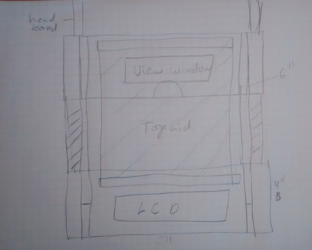
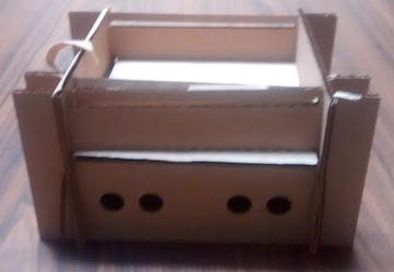
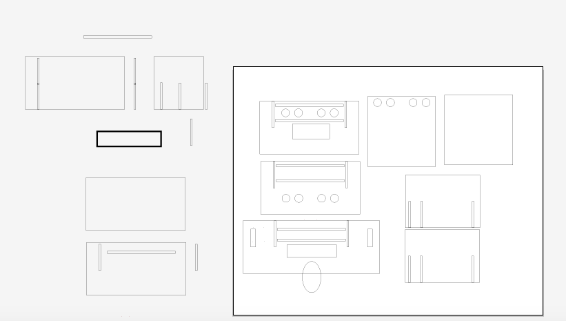
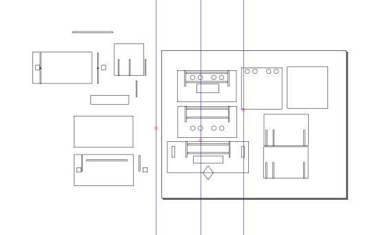
Below is my first goggle assembly demonstrating how the viewer would see the LCD screen.
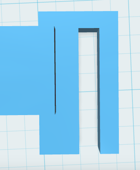
I had not yet figured out how I was going to attach the sensors. My thought initially was to attach them to the through a slot at the top of the goggles (see picture below). However I realized once I had made a version of the goggles that there would be no easy way to secure the sensors on the goggles.
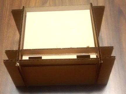
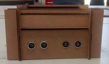
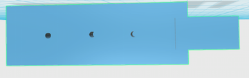
Once I cut my first mock up of the goggles it was obvious to me that the best place to put the sensors was on a plate at the front of the goggles. It would be very easy to just cut some holes out for the ultrasonic sensors. Other things that occurred to me after making my first mock up was that I could create a compartment at the top of the goggles for the battery and Arduino.
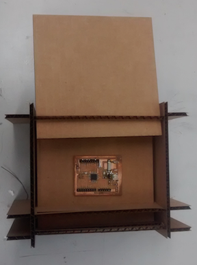
Once I had made the box to hold the electronics it occurred to me that I had to design a way to get the wires from the sensors and the LCD to the Arduino. This was easily fixed by putting holes in the horizontal and vertical plates the formed the upper box.
Holding the goggles to the viewers head
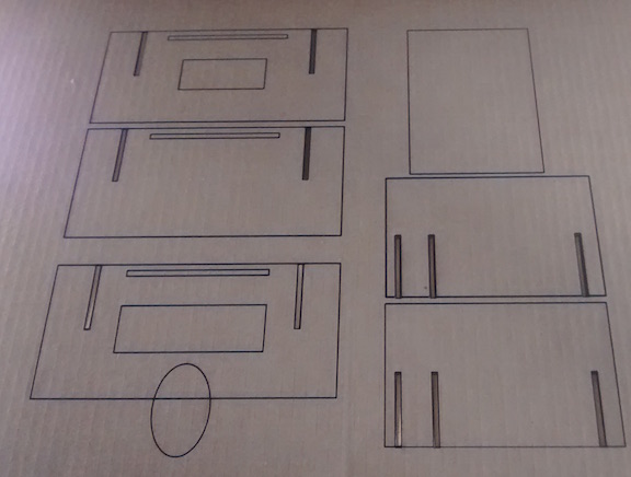
To hold the goggles to the viewers head I am going to use headband. I previously made a headband during week 14 composites. The process can be viewed here. My first idea for using the headband was to have it slot into holes cut on the sides of the goggles. I realized once I had made the goggles that the headband did not extend far enough forward for this to work. My solution was to use a 3D printed piece to form the attachment but initially I needed to make something that I could use for my project presentation. Using Inkscape designed a holder out of cardboard that folded and was slotted so that it had a horizontal slot for the headband and a vertical slot for the slotting into the sides of the goggles. The complete final cardboard cut on a laser cutter can be seen below (note the picture does not reflect extra holes I added into one of the plates).
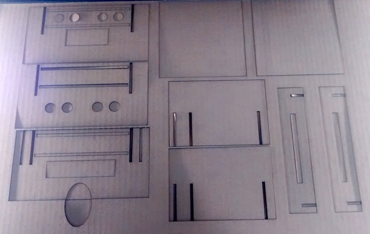
To dowload the SVG for the Laser Cut cardboard cutout click here.
This seemed to work very well. I was even surprised that I was able use the headband to hold the goggles onto my face with out my holding them up with my hands. This was true even when I loaded up all the electronics into the upper compartment.
Making the Bracket for the headband
I used 123Design to make the 3D printed bracket. My idea was to make something similar to the cardboard bracket except that the 3printed bracket would encapsulate the headband and thus be more secure.
The first step was to form a box of 60mm x 20mm x 20mm dimensions. I measured the actual diameter of the head band to be 5mm. I then created another box of 11x11 mm and did a negative extrusion creating a square hole through the box into which the headband would fit (for more on how to do this refer to week5 3Dscanning and printing).
P> 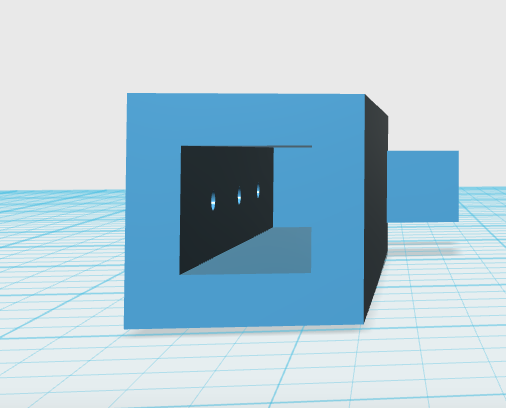
I then formed another box of 35x20x10mm dimensions. I snapped the opposing faces of the smaller rectangle to the back of the larger rectangle such that that the long face of the small rectangle was perpendicular to end of my large rectangle. I next merged the two rectangles so that 4 mm of the two rectangles overlapped, creating a single piece. Next I created extruded a slot in the smaller rectangle that was 30 x5 x10mm.
The last thing I added to the head band were holes 1mm wide that could be used to secure the headband into the holder.
Lastly I duplicated the bracket and the 3D rendering can be seen below
The file to 3D print the headband brackets can be downloaded click here.
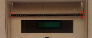
One of the problem I was having with the cardboard design is that it easily ripped especially at the slot where the upper plates slotted into the face plate. The cardboard here was very thin these points and easily rips when you try to slide the plates through the slots. Weak spots are highlighted with red circles
Remaking the Goggles in Wood
In my presentation Neil suggested that I use heavier duty cardboard. I looked into this option but I did not have any accessible. My design is parametric so it would very easy to use thicker cardboard in the future.
I did have on hand some thin paneling that we frequently use on the laser cutter. It is only slightly heavier than the cardboard but is a lot more durable. It is the same diameter as the cardboard so I used the same design to cut out a set of goggles on the laser cutter. The only thing that was a bit annoying about the material was it took five passes to get it to cut through when you used the same settings as the cardboard. I found slowing the laser cutter down to 5% speed and increasing the frequency to 40% allowed me to cut out the goggles in a single pass using a 50W Epilog laser cutter.
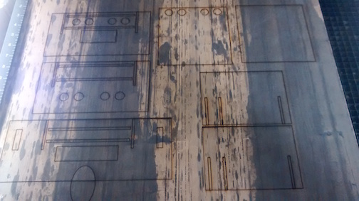
To download the laser cut SVG file with the rounded nose click here.
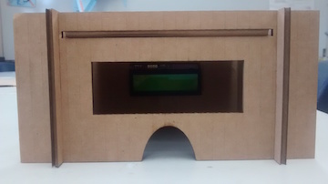
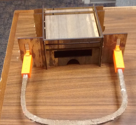
I then assembled the wooden cut out and added the head band with brackets. It all went together fine except that I had to enlarge the cut out for the LCD screen. The cardboard course more forgiving and I was not able to shove the LCD screen into the tight fit as I had been able to do with the cardboard. Conversely the cardboard did not buckle or bend when I put on the headband.
Making the nose Piece
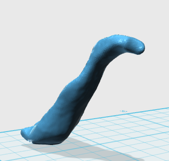
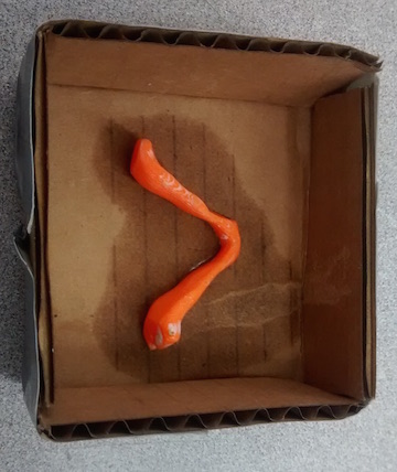
Another problem I was having with the cardboard and especially the wood design was the nose slot tended to dig into your nose. This was an expected problem and so I moved on next to designing a nose piece. I decided to use clay that I would shape to the contours of my nose and then 3D scanning which would then be 3D printed.
Making the clay form was simply a matter of taking a role of clay and pressing it around the contours of my nose. Scanning it ended up being the real challenge. Ironically the 3D scanning had been the most straight forward thing I did in the FABLAB, but before I was not worried about printing the object.
The problem I had in scanning my nose piece was that it would not scan the interior side of the nose piece. I initially thought it would work because the sides were angled out but apparently it still could not get a good enough read on the piece. As a result the side was just a mess of jagged edges and bulges that did not resemble the actual piece, as can be seen in the 3D rendering below
I tried initially making the clay object as smooth as possible but it did not matter. I also tried doing multiple scans and combining them and still it did not matter. Finally I decided the only way to accomplish this was to just scan one half. This worked really well and produced a scan that looked like the object
I then rebuilt the other half in 123Design by duplicating the scanned half. I then combined the two halves and rotated the piece so that both sides would angle slightly out. A 3D rendering of the object can be seen below.
To download the file for the nose piece click here.
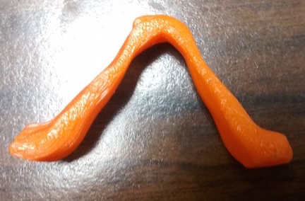
I then 3D printed the nose piece.
I next casted and molded the nose piece. First I made a box by cutting out a square piece of cardboard and then cutting out corners with an exacto knife so that the sides could be folded up.
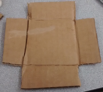
Next I folded up the sides of by cardboard and used duck tape on the conners to form a box. I then used a grinder to flatten one side of the nose piece so that I could glue it to the bottom of the box
Just as I had done in week 12, I mixed together the Smoothon Moldstar parts A and B in equal proportions and then let it set.
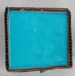
This was quick set so it only took about an hour before I could pull off my mold.
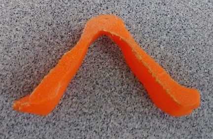
I then mixed together the casting material and poured it in the mold. Initially its starts off clear and then is white when it is done. It only takes about 20 minutes to set to the point it can be removed from the mold.
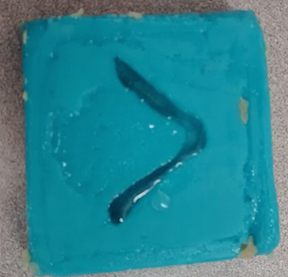
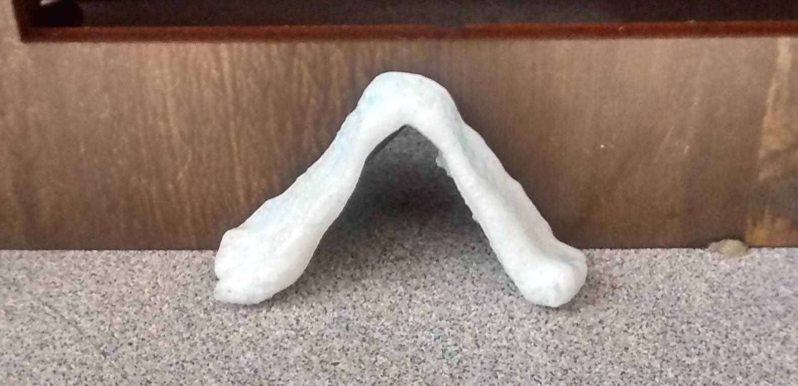
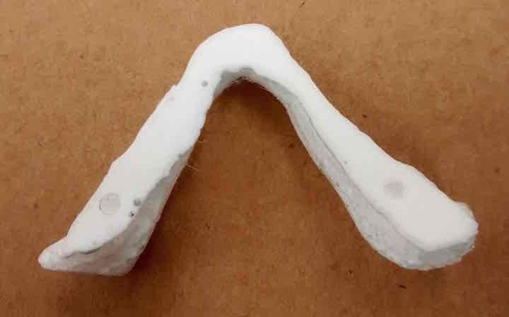
I then pulled the cast out of the mold and held it up to the cut out on the goggles.
Attaching the Nose Piece
Initially I tried to figure out a way to get the nose piece to fit into the existing hole I decided the best way was to attach the nose piece was with screws. Because the cut out for the nose was round this would not work because there were gaps where I would need to screw on the nose piece. Also I realized the front plate would need a triangle cut out to better fit the nosepiece so as to screw it on. Below is a layout with the triangle nose piece as well as the revised SVG file for cutting out on the laser cutter.
To dowload the SVG for the Laser Cut wood with triangle nose piece click here.
In order to screw on the nose piece I first flattened one side of the nose piece on a grinder and then drilled 1/8" holes in the nose piece.
Next I drilled holes in the goggles on either side of the cut out for the nose. I then screwed the nose piece to the goggles.
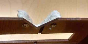
I then tried the goggles on to see if they would hold onto my face. I was very relieved when they did and it was a lot more comforatable on my face with the nose piece.
Wiring
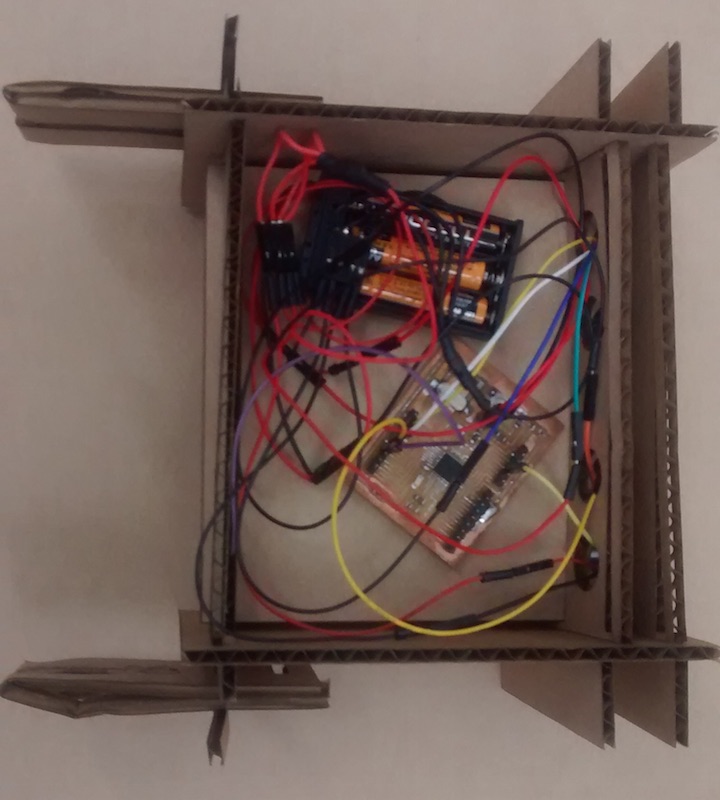
For a power source I was trying to decide between a 9V or multiple AA batteries. The biggest problem with the 9V was that it would have required making a breakout board with a voltage regulator to bring the voltage down to 5V. Alternately I could use three AA batteries that would produce 4.5V, which is sufficient to power the Ultrasonic sensor and the LCD. The other advantage is that although lower in voltage the AA batteries would deliver more current, which more important given the number of components that will be powered. To make the connections I first soldered four wires together and then to the power and ground of the battery. For the power and ground bundle wire, I placed shrink tubing I then made a female header for each of the power and ground. I then used jumper wires to hook up the rest of the connections. Admittedly it turned into a rat's nest of wires.
Clean up the Wiring
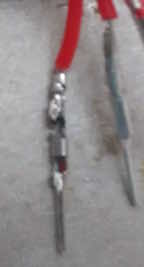
The next thing I needed to work on was cleaning up the wires as Neil had requested during my presentation. I fixed the problem by first shortening the wires coming from the battery pack. I remade the branching voltage and ground wires just as I did before with the insulation. The first time I made a header I used too much wire. When I put the header pin on the wire tip, the extra wire made for a very flimsy connections that was prone to breaking. Below is an example of a bad connection into a header pin.
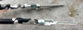
I realized that the better way to make headers was to have a very short wire sticking out of the insulation. Then when the wire is put into the pin, you can crimp around the insulation to make a more secure connection. I found it useful to put just a small amount of solder to hold the wire tip to the pin with an emphasis on small because when you put too much it made it impossible to get the pin into the header. Below is good header pin connection.
After soldering on the female pins for the four wires I then inserted them into the header. For the ultrasonic sensor I used a premade 4 pin ribbon wire that had female to female pins. For the voltage and ground I replaced the header with male pins, leaving echo and trigger wires female so they could attach to the male pins on the Arduino board. Likewise with the LCD display I changed the pins as appropriate and in addition added shrink tubing to keep the wires together. For the Voltage and ground going to the Arduino board I simply used male to female jumpers.
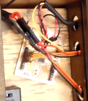
Below is a video showing the cleaned up wire arrangement. The video shows how the top plate can easily be moved in and out and that the ultransonic sensors and LCD display still work.
Securing the components
Once I had the wire mess under control I realized it would also be important to secure the battery pack and the Arduino. I initially considered using Velcro that glued to the goggles and the component respectively. The problem with this was that it would be impossible to slide the bottom plate out if there was Velcro glued to it. I decided instead to secure the components with screws. A single 1/8' hole was drilled in my Arduino board, in the sliding cover of the battery pack and the bottom plate. Small screws were then used to secure the components.
The video below shows the screws secure the components and they do not move when goggles moved.
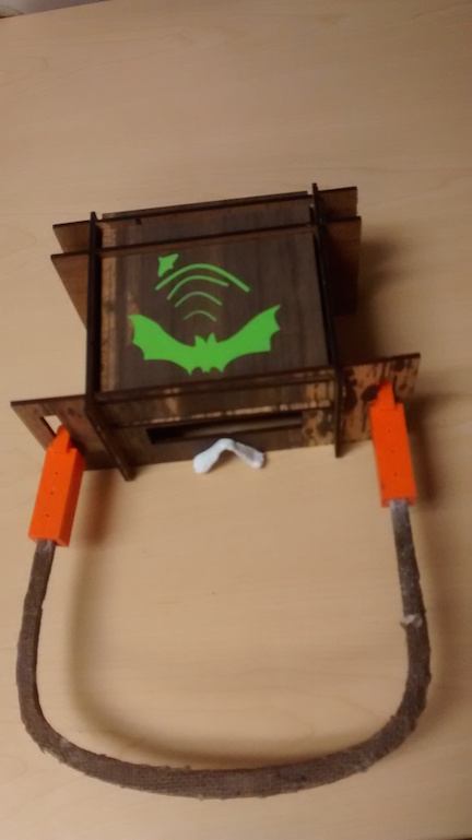
Finishing Touches: Bat sticker
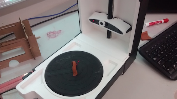
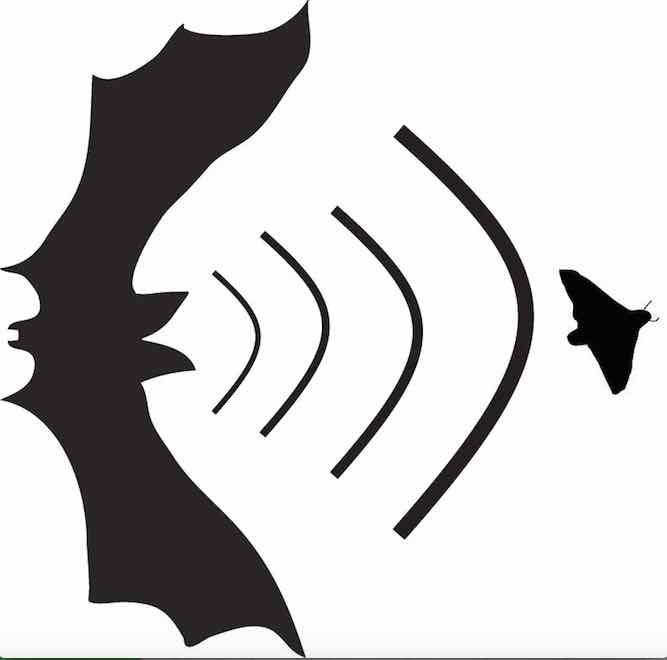
Next I wanted to add a sticker so that students would have a visual in order to understand the idea of ultrasonic location. I used the picture that I drew on Adobe illustrator of the bat emitting a sound wave and hitting the moth . I started by importing a jpg into the SILHOUETTE CAMEO vinyl cutter software and creating an trace (note the zip file with all the files has a high resolution version of the bat picture).
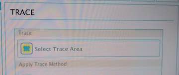
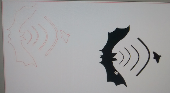
once I had a trace, I selected cut settings for standard cut
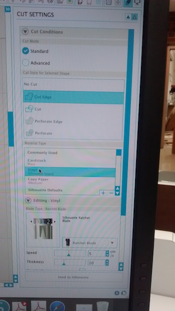
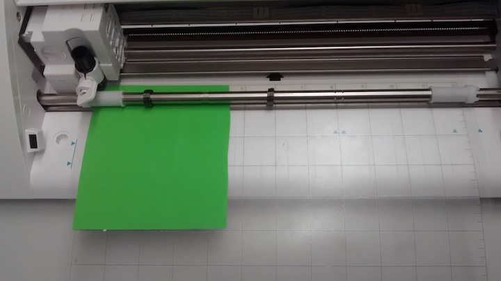
One difference with the SILHOUETTE CAMEO vinyl cutter is that the vinyl is placed on a cutting pad before it is inserted into the machine and then mat is inserted into the front of the Machine.
Once I had the sticker cut out I placed it on the top plate. Below is the top view of my completed goggles with the added sticker.