Exercise 15: Networking
Networking Using ATtiny44
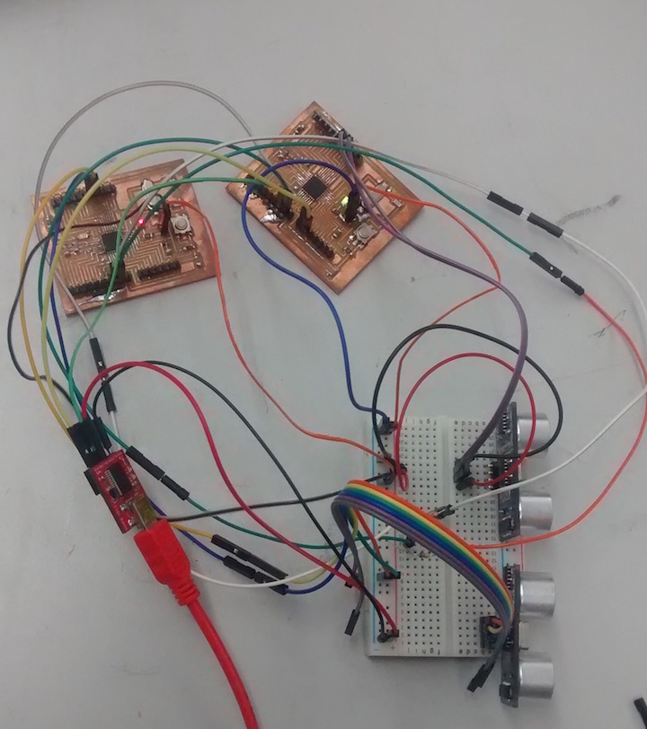
Making the Node and Bridge Boards
I want to have two ultrasonic sensors for my final project so I wanted to do a networking task that might relate to this goal. I found a previous project that used two ultrasonic sensors such that a LED light came on when distance data was detected. It worked by relaying the information on one of several node boards to the bridge which then relayed that information to the computer by serial input. click here .
I milled out two boards based on the design of JJ Fernandez design (to see his design click here . These boards were not designed using Eagle CAd so I redrew them in Eagle CAD based on the original design. The boards are essentially the same except I used a surface mount LED and 499 resistors.
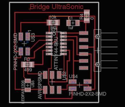
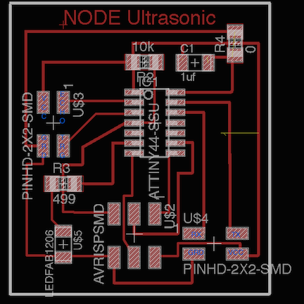
To download the files: To download the node schematic click here, Node BRD: click here, Bridge Schematic: click here., To download the brd click here.
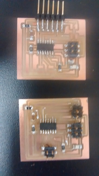
I cut out both boards and soldered on the components. Note that one board is missing a 4 pin header that I soldered on later.
Programming the boards
Both boards seemed to be working fine in that I could get them to communicate with the computer. When I tried to get the original code to work, I could not get it to compile. The error message said I had a conflicting declaration of software serial.
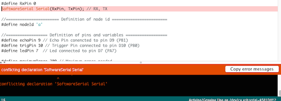
I fixed this problem by adding myserial to the serial declaration. I now understand that essentially you are declaring serial twice and so it creates a conflict. See error message below.
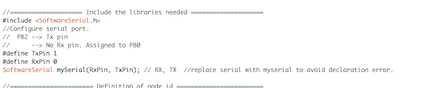
I fixed this by changing the “serial” to “myserial”.
The code then compiled fine. To download modified Node code: click here.
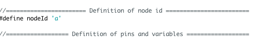
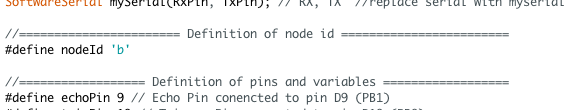
Once I fixed the code I was able to upload it for each of the two boards using the USBTiny programmer. The only thing that need to be changed when upload to the two boards was that for the Bridge board the code had to be changed to Node “a” and for the for the other boards it would be change to node “b” ect.
Hooking up the Ultrasonic sensors to boards
I then hooked up the ultrasonic sensors to the Bridge board and hooked up the board to my computer via a FTDI cable. Nothing happened. I got nothing on my serial output. I then tried my Node board. This was a bit trickier hooking up to the FTDI cable but basically I used the pins that would have been used for transmitting and receiving between the two boards and hooked them up to the FTDI cable. Still nothing.
To test the serial output, I next tried changing the code so that it serial output was just “hello”. This worked, both boards gave the serial output “hello”. From this it became clear there was something that was not working in terms of the serial output from the ultrasonic sensor. This is a similar to the problem I had when I tried to get the ultrasonic sensor working with an ATTINY 45 during the input week. The only way I got it working was to run serial input through an Arduino. The code seems pretty straight forward but at the end of the day I decided it was just not worth my time trying to get Ultrasonic sensors to work on the ATtiny’s. I have spent a ridiculous amount of time trying to get them to work, even getting help from my FAB Guru Terence.
.My conclusion about using ATtiny’s with serial output
I could not get the serial output to work with the ultrasonic sensor. This is the same problem with all the input boards that I have made using the ATtiny microcontrollers and the ultrasonic sensor. It is my conclusion that because they lack an embedded serial ability they just do not play nice with serial output, particularity when you are trying to work in an Arduino programing environment. I am sure it is possible to get it to get ATtiny microcontrollers to work if you really know what you are doing, and I imagine it helps if you are using actual C to program it. I decided it was simply not worth my time to keep messing with the ATtiny microchips since I do not foresee using them in my classroom for application that require serial output and equally importantly I now have working Arduino Clones, which I foresee using in my classroom a lot.
Using I2C and Arduinos for Networking
For networking I wanted to get two ultrasonic sensors communicating with each other. I decided to move on from trying to get the ATtiny’s to work with serial output. I used two of the Arduino clones I built for my final (to see the process of my making the Satshakit Arduino click here . The main advantage of using the Arduino for this is that I found a tutorial on the Arduino website that was very helpful and informative click here and also SparkFun has a really comprehensive tutorial click here . I have come to understand that the central idea of networking is to have a master that will control multiple slave inputs such that the master then sends the information to the serial output. The Sparkfun article explains nicely why the I2C technology is such a game changer. Basically as I understand it, without I2C serial communication, you can only get communication between two boards because data is asynchronous, which means that no clock data is transmitted and so the timing between the boards is tricky to set up and even when it does work the fix eats into the rate data is transferred. I2C essentially solves this problem because it creates a clock signal, the SCL and a separate data signal SDA. Because of this, the use of an IC2 library creates the potential for many addresses to which the master can send commands and receive data, actually 1008 to be exact. It is worth mentioning that the SCL and SDA lines are mislabeled on the schematic at the Satshakit website as shown in the picture below.
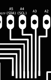
The pins are correctly labeled A4 and A5, but should read A4 as the data SDA pin and A5 as the SCL. I wired my networking boards as shown below. The SDA pins are wired together and the SCL pins are wired together. Note there is a 4.7 k resistor between the pins that is on the breadboard. This is recommended to ensure better communication between the pins. Refer to the Sparkfun link to read more details about the need for a resistor.
Arduino code for Networking Arduinos with Ultrasonic sensors
To write the code I started with using the Arduino examples for slave sender and the example for master reader. I started by adding the ultrasonic code and adding it to the Arduino master and slave example code to make an ultrasonic master code and an ultrasonic slave code. Both codes compiled but bizarrely when I ran the code I got weird numbers or no numbers from the master using the ultrasonic sensor.
I tried a new breadboard and used the original ultrasonic code. The sensors still worked so I went back to trying to write the code for the master and slave.
The next thing I tried was just getting the master and slave boards talking to each other just using the “hello world” as the output. I still could not get the boards to work. So next I tried just using the original unaltered master and slave code to just send hello. This worked great. So at this point I established that my sensors are good, my boards are good and the basic networking program works. This leads me to conclude that problem occurred in the code when I combined the networking code with the ultrasonic code.
This time around I tried a different strategy. I tried putting the example code for networking and put it into the ultrasonic code because it is a lot less code.
The first thing I did was to put the library for I2C at the start of the code: #include
For the master code in the “void setup” I added- Wire.begin(). For the slave I added- Wire.begin(8), which is the slave’s address.
For the master within the void loop, in the an if/else structure was added and under the else the “Serial.print("\nMaster value = ")” was added. Adding the “\n” was added for clarity of display because it provides an extra line between the master value and the slave value
.Following the “else” structure I added the “Wire.requestFrom(8, 1);” Which indicates that address it is requesting and the amount of data it is expecting, in this case 1 byte. Next in the “while” structure I added “int slavedistance = Wire.read();” which instructs the network get the integer value from the slave. I then added the command to serial print the slave value and display slave distance.
For the slave code there was not much change. Like the master I added the wire library. Next I assigned the slave with the address of 8 by adding “Wire.begin(8);”. The other thing I added from the slave code was “ Wire.onRequest(requestEvent); // register event”.
The code now successfully compiled and uploaded to the boards. I uploaded the master code to one board and the slave code to the other using the wire diagram discussed earlier
.To download the final master code for the ultrasonic sensor click here.
To download the final slave code for the ultrasonic sensor click here.
Using the Networked Ultrasonic sensors
The code worked great displaying the data from both the master and the slave Arduino ultrasonic sensors. The video below shows the network boards communicating and displaying distance from the two ultrasonic sensors.