Exercise 13: Output Devices
Reason for Building the board
I decided to make a speaker output board because I may use the speaker as an output for my final project.
Designing the Board
Starting with Neil’s design and changed it in two ways. Neil’s design has separate four pins jumpers for the power and for the speaker output, each only using two of the pins. I decided to combine these into a single four-pin jumper.
The other minor change I made was that I had to add a jumper because I could not get a clean trace to go through the middle of the regulator as in Neil’s design. It is worth mentioning that I figured out how use Other Mill software called Otherplan to check traces. I found that if you upload the brd file into Otherplan and set the bit you specified, you can see where the traces will touch. Having said that I also noticed that in many cases it does not make sense. I found many places traces where running along and for some reason in the middle they touched. I think it must be a flaw in the software in how it calculates the tool paths but in any case it is useful to do and saves having to cut boards that will not work. In this particular case I saw that the trace running through the regulator was touching.
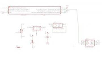
 For schematic ( click here.) for the brd ( click here.)
Milling the Board
After cutting my board I was very annoyed to see that there were metal fillings from where the bit did not cut the board cleanly. To fix the problem I took a hypodermic needle scraped the edges of the traces and then washed the board. One note, on a previous board I put flux on the board before cleaning edges and this only accomplished encasing the filling in flux goo. Moral of the story is make sure your board is free of spurious filings before applying flux, they can be removed but this requires digging them out with a needle.
Soldering the Board
I next set to soldered the components onto my board. The first thing I needed to do was figure out the difference between a regulator and a transistor since they look about the same. I now understand that a regulator controls the voltage so that voltage stays within a safe range while the transistor increases the signal.
Programing the board
For this board I wanted to use C rather than Arduino so that I could gain experience with it. Former Fab Lab participant Adam Harris helped me use Neil’s code to program Neil’s board. We used Win AVR to program the board using Neil’s C code for the speaker board. What I then recreated the steps using this tutorial click here ., which outlines the steps that Adam showed me (skip to 8:00 for steps on programing). The basics steps outlined in the tutorial are that the program are as follows:
1. Write or paste the code into Win AVR programmers notepad.
2. Save the file into its own folder and name the file-main.c (note that when there are unsaved changes there will be a * next to the file name)
3. Next you must create the make file using the WinAVR program called Mfile. This is the file that will tell AVRdude to use the correct microcontroller and use the correct file to program it.
4. In Mfile you need to change select the chip that is going to be programed.
5Next the programmer must be changed. USBtiny was not listed so I selected a programmer from the list and that highlighted where the programmer was listed in the make file. To fix this go to the make file and enable editing. Then change the programmer to “USBtiny”.6. Next the port needs to changed to USB.
7. Then save the make file in the same folder as your main.c file.
8. Go back to the programmers notebook and then go to tools and select make all.
9. If there are no errors the chip can now be programmed by going to tools and select program.
Playing the speaker
What was weird was that the speaker board was able to communicate with the programmer and seemed to be programed but the speaker did not work. Interestingly we discovered if the speaker was placed so that it received a signal prior to the transistor then it would work, just very softly. That is when we realized the problem was with the transistor. It turns out I was using a P type transistor rather than an N type. For a discussion on the difference
click here The basic difference is the direction of the current going through the transistor. I did not know the difference between the N and P transistors when I soldered the board and assuming that both would work since both were listed on the Fab Academy page and there being a 50% chance of me picking the correct one, Fab Law dictated I of course chose the wrong one. The correct one is the N type resistor, I chose the P. In defense of the Neil, it does say N next to the resistor on the layout of the board, but I did not know that there was even such a thing as different types of resistors so that did not mean anything to me.Once I replaced the resistor with a N type the board worked great.
Conclusions
Now that I have programed a board using C directly I see it is not that big of deal. I still prefer using the Arduino environment for programming. The reason is that I am long way from actually being able to program in C whereas I am getting pretty comfortable manipulating code in Arduino. Also uploading code in the Arduino environment is just a lot easier and takes less steps.
.