Exercise 9:Mechanical Design
Making the Machine
4/04/2016
We received our modular machine yesterday. We downloaded the .dxf file at the original site that developed the modular machine click here and tried to put it into Corel draw so that we could print it out on the laser cutter. I have only used the laser cutter a few times so I was not sure about the differences of line colors and width. I spent time switching the blue lines to hairline and I left the red lines wide thinking that would be fine for etching. When we tried to cut, it only cut the blue lines and completely ignored the red lines. This was very annoying because I could have just selected all of the lines. In any case it did not work. In the process of trying to change the size of the objects the circles became distorted and were not the correct size.
I next tried the .dxf file from the link above and opened it in Adobe Illustrator. This seemed to work very well. When I opened the file in Illustrator I selected to open the file as the original size. I used the ruler for the canvas. It appeared that the size of the object that forms the main track was 28” x 28” once you include all the rails that stick out from the object. This is a problem because the laser cutter only has a stage of 30” X 20”. Tried to manipulate the object that makes the main box but I could not figure out how to just make it shorter without changing the dimensions of the whole object. I decided to go ahead and save it as a PDF to see if I would have any luck manipulating it in Inkscape.
When I tried to save it as PDF and open in Inkscape I realized that it only showed the small part of the image that was over the canvas. To fix this I went back to illustrator and selected File and then document setup. In document setup I selected Edit Art boards which then allowed me to expand the canvas to include all of the objects.
I then saved the file as a PDF and opened it in Inkscape. One thing I like about Inkscape over Illustrator is that I cannot find a way to easily check the size of objects like I can in Inkscape. The size of the objects appeared to be good except for the fact that the main box is definitely too big to fit on the laser printer. There does not appear to be any way to manipulate the PDF in Inkscape.
3/05/2016
When Tom tried to print the PDF we first split the objects up into separate documents using Corel Draw. In the process of doing this Corel resized the objects and the holes became distorted.
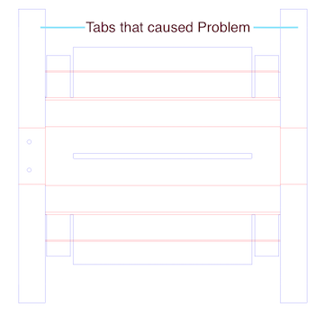
When I tried to cut out the pieces and I did figure out how to put the main box together. Once I put it together I realized the long tabs that were causing problems by making the object too big could easily be cut down without affecting the box.
Later I was playing around with Illustrator some more and realized that if I used the eraser tool I could just erase the top of the tap making it fit within the 30x 20. Happily when I did this it seemed to solve the problem. I then saved it as a PDF file.
Later I was playing around with Illustrator some more and realized that if I used the eraser tool to shorten the tabs. Happily when I did this it seemed to solve the problem. I was able to shorten offending tabs that made the object too big to cut on the laser cutting.

When I put the PDF file into Corel draw I realized that the words that tell to print face up or down were still there. I could not see them in Illustrator. It is not really clear what that means. I think it has to do more with how it is folded not printed.
To print the pieces I had to split the pieces up by creating a canvas for each piece or set of pieces. I created four files that fit into the needed area: one for the main box , one for the top and bottom of the sliding box, one for the side one for the support structures.
The files are downloadable below. I have separated the pieces into a PDF file that each will fit on the Epilog laser cutter.
For the main tract: ( click here.)
These reinforcement pieces are not modified but have been separated out to fit on the laser cutter ( click here.)
These stage pieces are not modified but have been seperated out to fit on the laser cutter click here.
Update: I do not know if I did not notice this file before or if they just added it to the MIT Modular machine here is a file for the whole modular machine off the site that I have converted into a PDF file ( click here.)3/06/2016
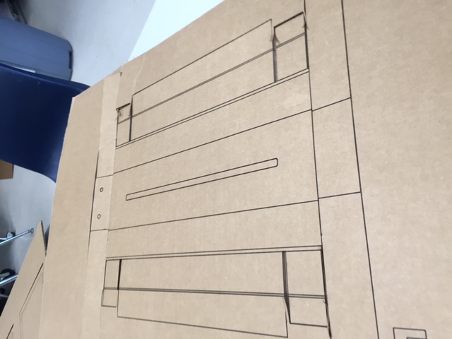
I cut out these pieces on the laser cutter. Unfortunately the laser cutter is not cutting the red and blue lines differently. As a result we only etched and then cut out the pieces with an exacto knife.
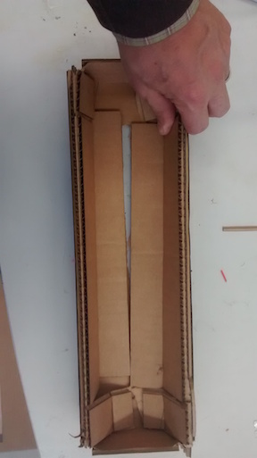
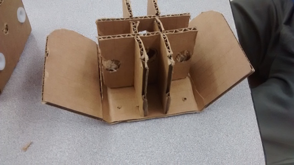
After cutting the pieces using razor blades. We main track together using a double sided tape gun and glue. This involved folding the pieces in as shown in the picture below.
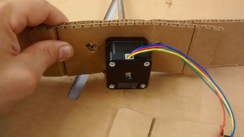
At the same time you make the main track you must assemble the cardboard plate that will hold the motor because it must slip under the flaps that form the sides of the main track. Note that four brackets two for the motor and two that will hold the rods on the other end of the track. These pieces will be glued together such that their flaps point out in opposite directions. It is also helpful to attach the motor before putting in the pieces.
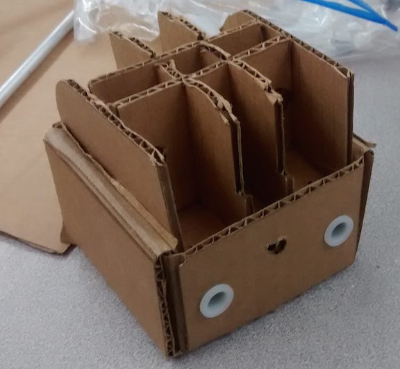
Next we built the stage for the machine. The stage has three pieces. The bottom piece has the two rounded flaps and an interlocking inner structure. Make sure to orient the holes as shown in the picture below.
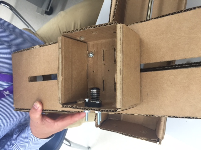
The other piece forms the main stage and is a box that the previous piece slips into. There was some confusion as to which direction the bottom piece went into the main stage. Below is a picture showing it incorrectly placed. We next oriented the bottom piece correctly, with the rounded edges turned in, which is I guess the reason the edges are rounded so that they will slip into the main stage. The last thing we did to the stage was add the black bracket which is bolted on the inside of the stage and to which the drive shaft of the motor will screw into.
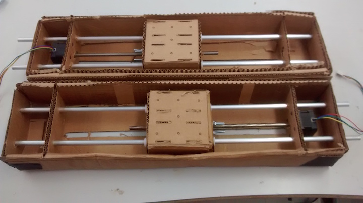
Once we had all the pieces we then placed the main aluminum rods through the holes and the stage. The drive shaft should then be screwed into the motor shaft.
Conclusions
When I started out I did not really understand what we were building and so I thought we had to make our machine exactly as was previously designed. In reality we could have done something slightly different. If I had known this I think I might have done some things differently. Mostly I would have redesigned it out of wood and cut it out with the laser cutter. It would have been stronger and it would not have required all of the folding. The reality is that cardboard is just not very durable or precise so by the time we were done our machine looked pretty messy despite working very hard on it.