Exercise 4: Electronics Production
Background on ISP
This week are tasked with making a FABISP programmer. I have no experience with programmable circuit boards. I found a very good document from Amtel click here. that explain the purpose of an ISP. First off ISP stands for In System Programmer, which means you do not need to remove the chip to program it.
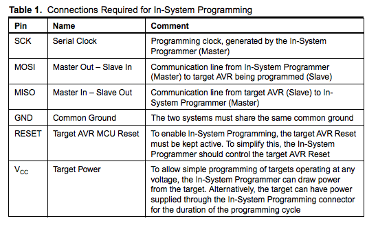
Below is a particularly useful chart from the Amtel document because it explains the function of all the pins that hook up the ISP
Milling with the OtherMill
2/17/2016
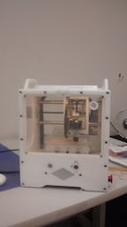
We are using a different machine for making our circuit board. Because of cost we are using an Othermill by Other Machine Co ( click here.) . The first thing we did was the introductory project called “Hello World” which can be made into a light up circuit board. This involved downloading the program into the OMC program and then downloading the Hello world file.
Following the directions on the Othermill tutorial we next set up the tool. Orienting the bit was very easy with the Othermill. We then selected the material and next the type of cutting. I learned that there are three types of cuts: Traces, holes and outlines. Holes are obvious but traces are the lines that will be the circuit and outlines will actually cut through the board.
One issue that we immediately realized would be a problem was that OtherMill uses .brd from EagleCAD. The file for the Fab academy circuits are .png because they run on the FABMdules. We found David's FABISP was in .brd. The only problem was that the file was too old. So we then downloaded the Eagle and re-uploaded the file. This updated and then we were able to upload it to the Othermill.
02/18/2016
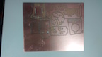
I tried to cut my board using the Othermill. I did everything exactly as I was supposed to but for some reason one of the paths did not cut. The lesson I learned is that you should vacuum and exam board before cutting it out of the copper stock plate. I am pretty sure if I had noticed before I could have gone back and cut it a second time. There are two possible explanations for the reason it did not cut that path. I am suspicious that this happened on the second circuit board that we tried to cut on that plate. I wonder if when we pulled the plate the act of detaching the tape somehow warped the board. Given the tolerances I do not think this is unreasonable. Second I may have placed the board too far off the edge of the base. In the future I will use less tape. The directions say to give the board a slight overhang on the base but I may have put too much.
2/19/2016
I cut my board today. I used a board that had been used already and it did not seem to cause a problem. Perhaps it was the overhang. In any case it is irrelevant because I figured out how to cut multiple boards at once and move where on the board the mill will cut thus obviate the need to remove the board until it has been fully used.
To cut multiple boards you need to import the board multiple times. Once you have imported the desired number of boards you can then click on each import and move it around to the place on the board you want cut. Next you have to set it to trace and then cut visible. I was able to cut out three more boards all at once. Given that it takes about 3 hours for the Othermill to cut a board, being able to set it up and walk away is a nice option. It is worth noting also that we talked to the manufacturer and they said there are ways to speed up the cutting once we feel comfortable using it.
We next tried to build our boards. We soon realized that the board we thought we cut was not the same board. We realized that the board diagram we were using for parts was Neil's board not David’s. The confusion came from the fact we had to search for a .brd version of the board.
Lacking the parts we decided to start to practice soldering a board. We watched several YouTube videos on surface mounting ( click here ) and it seemed easy. It was a pain. I am sure I could get good enough to do it efficiently but I wonder if the average high school kid would not. We decided to also get an infrared oven and use solder paste.
2/20/2016
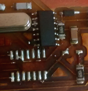
We received the overnighted parts along with the oven. Putting on the chips with the solder paste was very easy. We used a 20 gauge hypodermic needle to add the paste with more precision. The first thing I did learn was to put the USB port on last. The capacitors and resistors held in place with the paste but the USB port was too heavy and moved around every time the board got knocked.
Next we put it in the oven for seven minutes. It came out looking great if not a little burnt. The other thing I learned is that despite what I understood from the videos which recommended putting a line of paste on the board, it is better to put paste on individual pins for the USB port and the chip. In both cases I had shorts that were a pain to get rid of using a solder wick. Once we got rid of the visible shorts we hooked the chip up to the USB port on a computer to see if it would short, which it did not.
When we checked the fab academy web site we realized that we were missing the connector for the jumper cables. We finally realized we had some headers that had an L shaped connector and to get them to work we had to take two rows of three and face them towards each other and glue them.
1/22/2016
I finally made a board but not without one last “you’ve got to be kidding me” learning moment. A fellow Fab Lab student who had not yet made his board sat down today to make boards. After going through it once already on the failed board, placing the pieces on the board went fast with the solder paste. I put my circuit board in the oven and I started to hear a popping sound that I did not remember from the last time. When I took the board out I realized that there had been a small piece of tape I did not notice that was underneath the board. When the oven heated up the board, it caused the tape to bubble up which had the result of knocking my processer far out of place.
It was an easy fix but very annoying. The only upside is that I did get to experience repairing a board and surface mounting a multiple pin processor. I did this by placing a strip of solder across the pins and then wicking it off. After all of that I was very relieved when I plugged it into a computer via the USB and it did not short.
When we tried to program the board it failed to initialize. Initially it appeared that the board was communicating with the programer but when we tried to program the board it failed. We have put out emails for help to the Fab community and to Adam, a former FAB Academy graduate and PhD electrical engineer. On his recommendation we decided to try a different board.
Starting over with a different FABISP
We next tried Zaerc's board. I tried to hand solder the board with just solder and the soldering iron. From trying to fix previous version of the programmer I feel like I am getting better at surface soldering. To solder the board I put down solder on all of the pads on the board and then went back and added all of the pieces. Although I thought my soldering looked good the first time I tried it still did not work. It still did not work when Adam looked at and tried to program. We could get the red power light to come on when it was plugged it into the USB but it would not program.
Making the Zaerc's updated board and it worked this time
Next I tried the updated version of Zaerc's FABISP. We got the eagle file for Zaerc's board's from Adam's Sheek Geek website ( click here ). Note that I have the zip file at the end of this document that contains all of the Eagle files and firmware for programing.
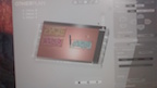
Here is a picture of the Eaelge cad picture of the FABISP that I got to work.
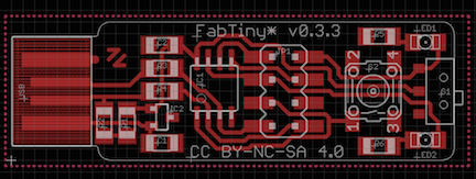
I am going to document at this milling circuit boards on the Othermill at this point because this is the first board that I milled by myself. I loaded the Brd file onto the Otherplan by importing a file and it will bring an image onto the OtherPlan GUI (note only brd files can be imported). When the file is first imported the tool path for the default 1/32" bit is shown. I point this out because it looks like the board will not cut correctly.
. 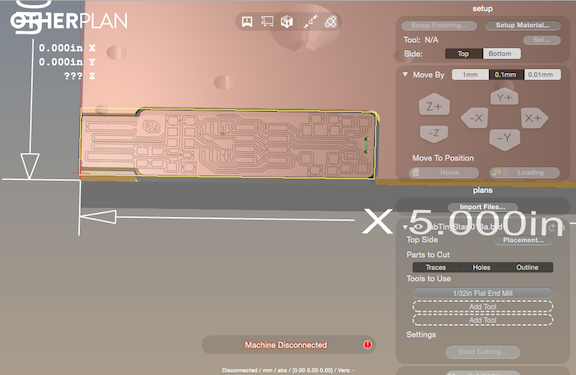
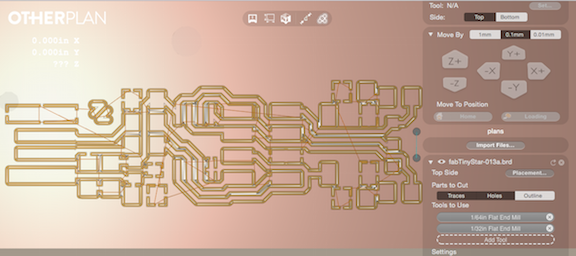
Once you have the board uploaded then you select 1/64 and then deselect outlines. As will be described next, the Othermill cuts with the 1/32 bit first and if you have the outline selected it will cut the board out of the stock before you are done. The Otherplan will then prompt you to insert the 1/32 bit. The Other plan will then go through a series of operations that zeroes out the bit to the stage and then it will start cutting. Once it has finished cutting with the 1/32 bit it will prompt you to insert the 1/64" bit.
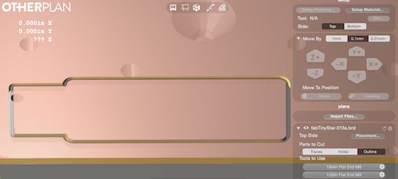
Once I milled out the board I then added back in the 1/32" bit and only selected the outline.
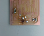
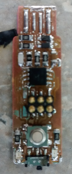
I decided to use a hybrid of surface soldering and solder paste. I really like this method because for the smaller pieces it is easier to place them with the solder paste. To melt the solder I used a heat gun set to 350 degrees with a medium size nozzle. An important note about the heat gun: at first we were not using any nozzle and then I realized from watching Neil's video that there was supposed to be a nozzle on the heat gun. I first used the smallest nozzle because I thought it would give the most focused heat. I found that this did not work because with the small nozzle it created air flow that pushed the pieces around. I actually found the larger nozzles worked better. I made sure that all my joints had good solder joints and then I went back with soldering iron and added a touch more solder.
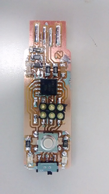
As far as I could tell the solder looked great but when I plugged the FABISP into USB to give it power the red light came on so I was feeling very confident it would program. Unfortunately when I tried to program it failed again. I was really stumped because I honestly did not think I could solder the board any better. After feeling really despondent for a few hours I pulled myself together and took a Multi meter to my board. I tested each of the different resistors and capacitors and they all seemed to work because the Red LED light came on. Then I tested the second LED with the multi meter and it did not work. I took off the Green LED light and replaced it with a new one and now the green LED light turned on. In the end the LED lights were both a savior and a problem. I learned to debug my board using one of the LED lights but the second LED light ended up being the problem.
Programing the ISP
Now I was officially ready to program my FabISP. We followed the directions of the former FAB Lab graduate Adam who posted directions on his Sheek Geek website click here . This page goes through how to use AVRDUDESS, which is a very nice GUI for programing the FABISP. AVRdudess can be downloaded ( here ). We tried programing our FABISP using terminal commands and while I do not think that was really the problem with our previous boards, it was much more cumbersome. Needless to say after many days and countless hours of frustration I finally got my FABISP programed using the directions for AVRDUDESS.
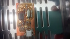
Before we could activate our FABisp we needed to hook up our programmer to a programmer. This is one of the catch 22's that Neil discussed in the lecture. We used a USBtiny as our programmer. The USBtiny has a 6pin head that is attached to the header. I discuss this in more detail in Week 8 embedded programing. In addition the board needs power and so the board is plugged into a USB. As described above, one thing I like about this board is that it has an LED light so that as soon as I plug it in I at least know it is getting power.
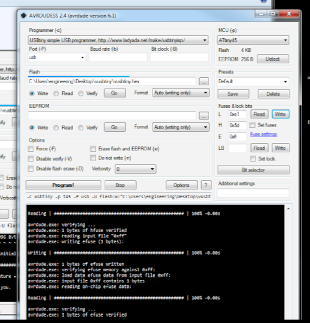
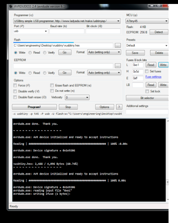
Below I have copied the directions from Adam's Sheek Geek site that we followed to set up AVRDUDESS
Using a Windows machines, I installed the Arduino IDE which will come with AVRDUDE. Search through the installation folders of the Arduino IDE to find the AVRDUDE executable program. I then used AVRdudess or another AVRDUDE GUI to program it using the following setting:
Select the main.hex file from the firmware folder
Select the chip as Attiny45
Select the appropriate connection info for your current AVR programmer, which you will use to program this chip. Again you can use an Arduino as an ISP programmer for this.
Fuses:
Low: 0xe1
High:0x5d
Extended: 0xff
Below are the pictures showing the setting that I used in AVRDudes to program my FABISP
Here is a Zip file that contains the eagle files for both versions of Zaerc's boards as well as the firm ware for programing the FABstarISP click here.
Conclusions about Making an ISP
In my humble opinion, while I understand why it’s important to have your own ISP, I am not sure it's the best thing to start off making your own FABISP when you are learning to surface mount solder and program boards. Of all the things to solder it was probably the hardest. Also when you are moving forward making your other boards I was very reluctant to use my FABISP. There are so many things that go wrong with programing boards that adding another variable in the form of my FABISP seemed hardly a good strategy, so I pretty much just stuck to using manufactured USBtiny. Now on the other end of the FAB Lab I do like the idea of having my own programmer but it’s because I now actually know what I am doing. My only point in saying all of this is that from a practical point of view as can be seen by the number of iterations we went through to get this working, it was a huge stress that I believe was not necessary.