
Introduction
During the 6th week we have gone deeper on a subject that we started during week 4. Back then it was about electronics production and, this time, about electronics design.
We have gone through the basic understanding of most of the components in a very simple circuit board and we have learnt how to use Eagle, a software made to both schematically design a circuit and then graphically design the board to continue later on production.
Assignment
We have been asked to redraw the echo hello-world board, adding at least a button and an LED. Important to check the design rules, and finally, to make it the same way we made our board during the 4th week.
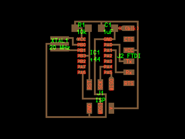
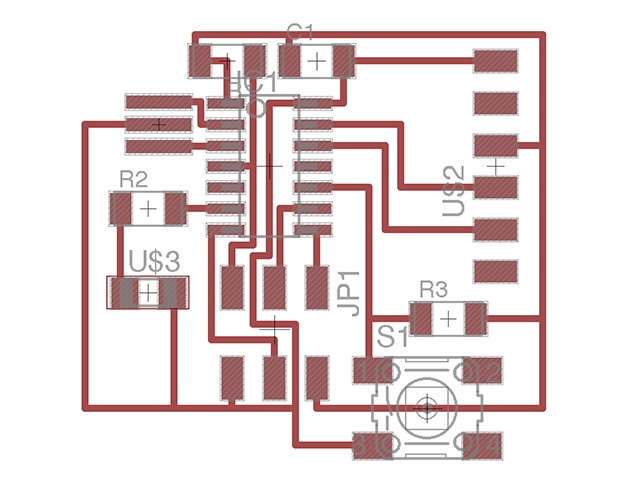
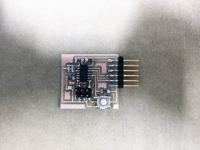
Basicallt, the best strategy is to start drawing a schematic view of the circuit by understanding the board view provided to us. This is an image of the board view where we can understand all the components in place:
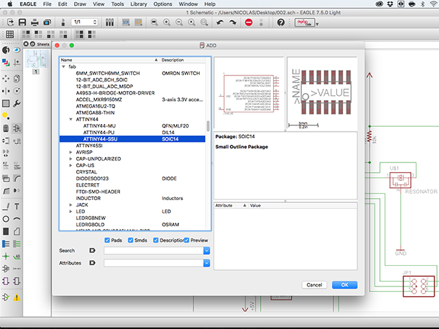
We downloaded and learnt how to use Eagle, a program that has a free version that is fully functional (almost) to the challenges we are facing so far. The way Eagle works, is based on having a library of components and, although there are already some components pre-loaded in different libraries, there is a "FAB" library available for download here. If you download the library, you just need to place the "fab.lbr" file inside the Libraries application folder. Once there, either restart Eagle or run the Library > Update All command to be sure it appears where it should. It should be something like this:
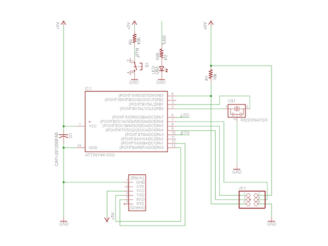
Following what we had learnt and by seeing how the original board was created, I added all of the other components into the schemativ view and then started joining them. There's a good tutorial on how to use Eagle that also explains the production of this board here. I also added the button, that needed to go to a specific PIN in the micro-controller and the LED that also needed a resistor, otherwise it'd blow! This is the result of the schematic view:
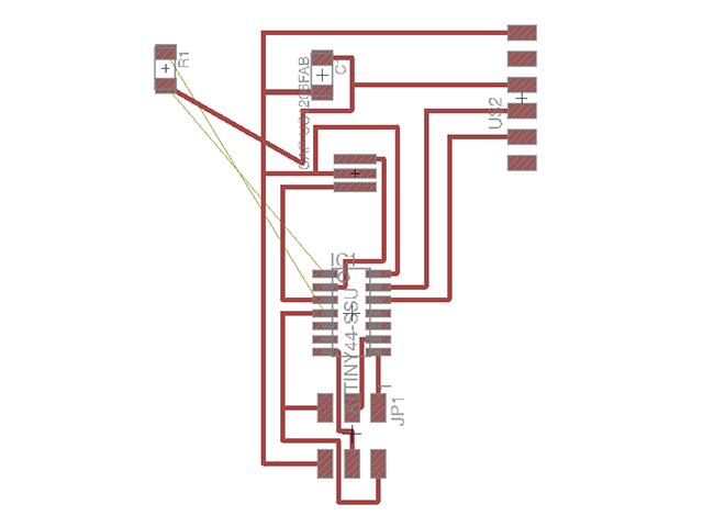
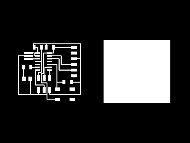
After the schematic view, it was time to design on the board view panel which is linked so it already contains the components, although without any particular order. I found that it is important to start connecting from the micro-controller to the rest of the pieces (headers, for example). And to make this with the least amount of paths possible. It may sound obvious but in the beginning I was trying to do this by designing the board as I thought it would look just pretty... It didn't work:
Finally, I did it as closest as I could to the board view provided. The board view looked like this and it presented no errors:
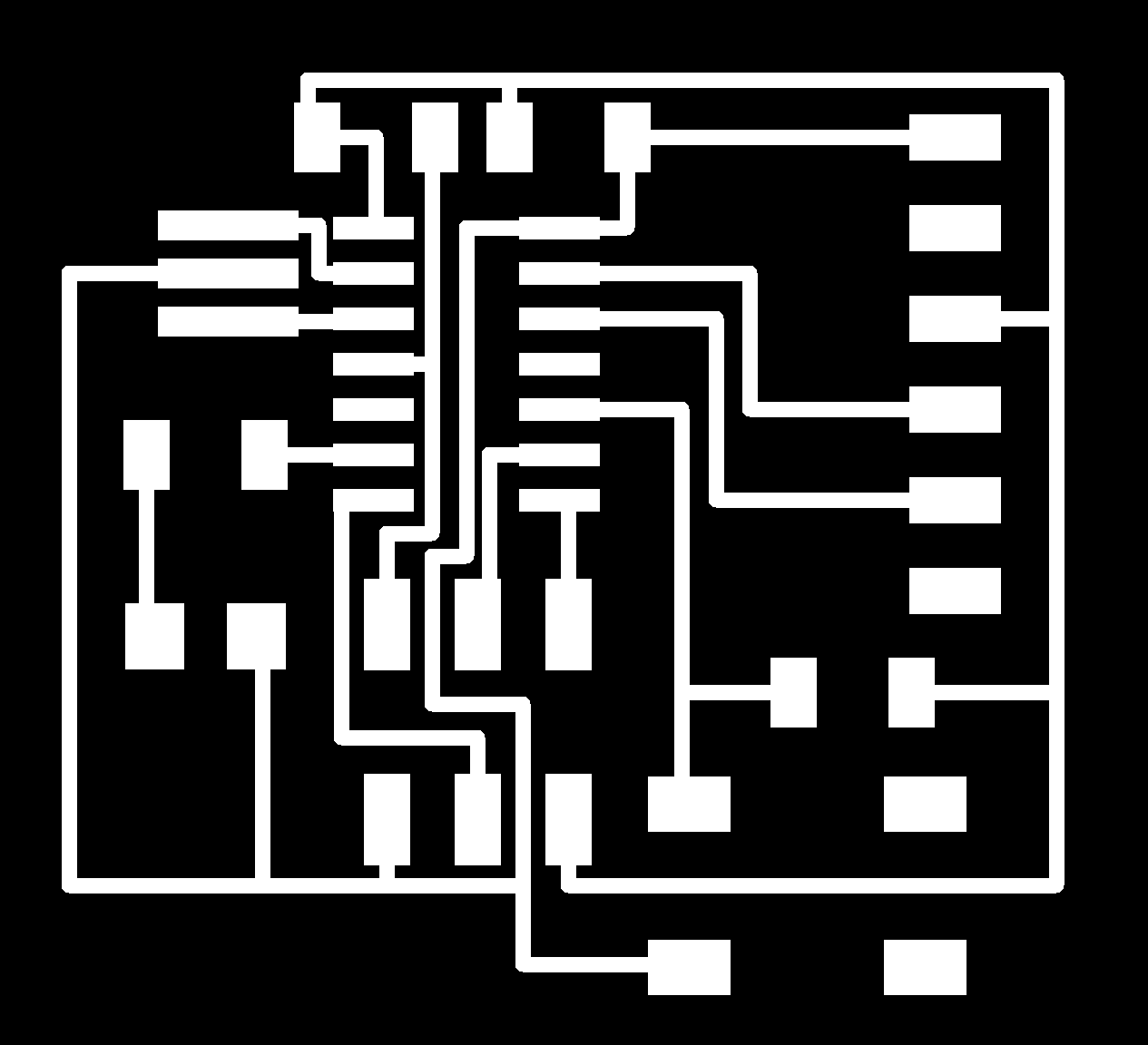
This is perfect so it can be exported as a PNG file (for the milling machine, to start production!), choosing monochrome settings and only turning on the layer "TOP". The image came out with a white background and black traces and pads, although it had to be opposite. After accomodating a couple of things using GIMP and also creating the border of the board, these were the images I had:
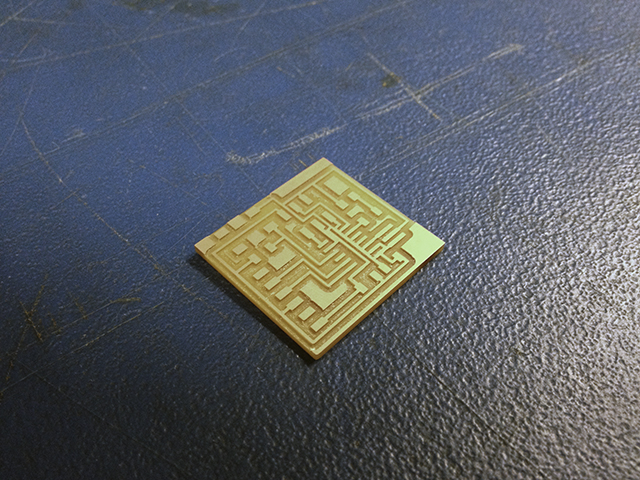
After going through all the process that I went through during the 4th week (click on link for tutorial on how to MAKE), I ended up with a pretty board!
Now I have to do my favorite thing in the world which is soldering (NOT). I got all of my things together, I remembered to solder the LED in the correct direction and, although it was harder than the last time I soldered, I managed to do it!
The crystal is the one I have doubts about, I hope we can try it soon and see if it works.