Communications //
For this assignment we had to design, build and connect several wireless or wireless nodes with network or bus addresses in order to create a network that would allow communication between different cards.
The communication protocols between processors can be of different types, for example the UART, SPI and I2C protocols.
>
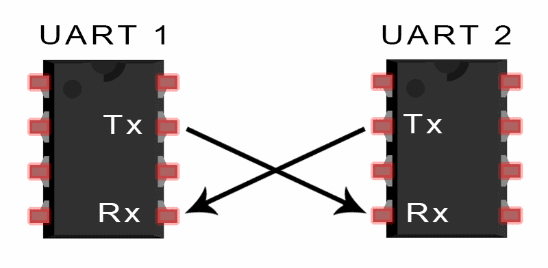
UARTA universal asynchronous receiver/transmitter (UART) is a block of circuitry responsible for implementing serial communication. Essentially, the UART acts as an intermediary between parallel and serial interfaces. On one end of the UART is a bus of eight-or-so data lines (plus some control pins), on the other is the two serial wires - RX and TX.
>
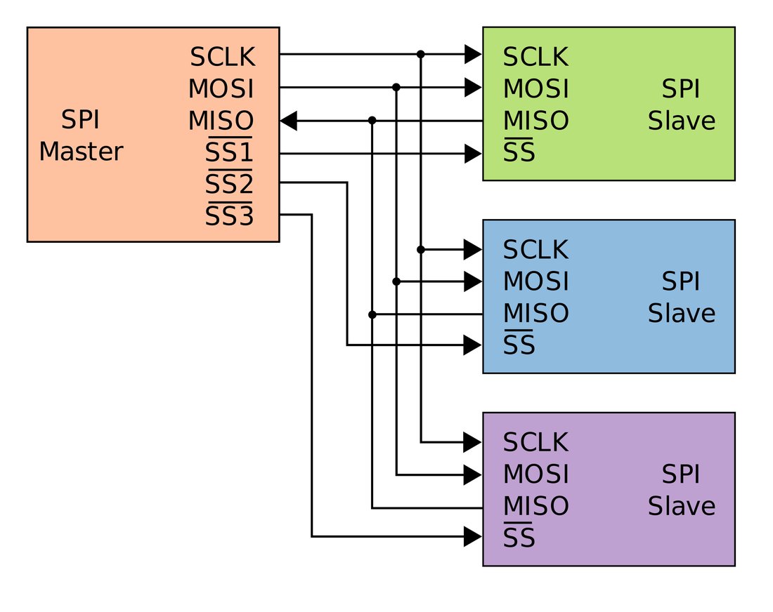
SPIThe SPI Bus (Serial Peripheral Interface) is a communication standard, used mainly for the transfer of information between integrated circuits in electronic equipment. The Serial Peripheral Interface Bus or SPI bus is a standard for controlling almost any digital electronic device that accepts a serial bit stream regulated by a clock (synchronous communication).
>
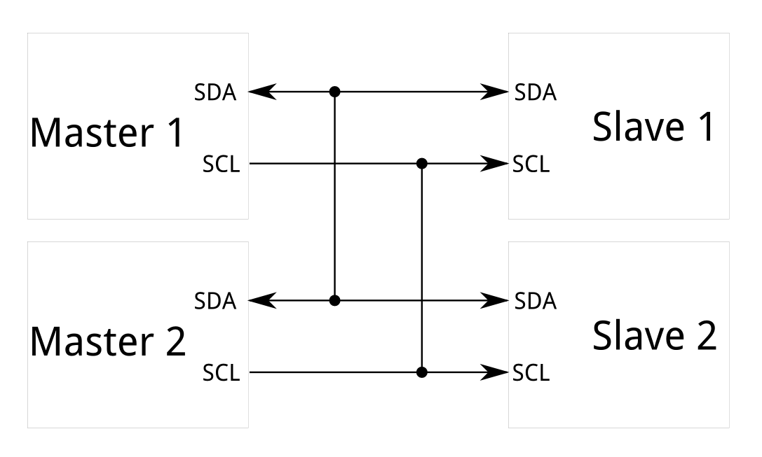
I2CThe Inter-integrated Circuit (I2C) Protocol is a protocol intended to allow multiple "slave" digital integrated circuits ("chips") to communicate with one or more "master" chips. Like the Serial Peripheral Interface (SPI), it is only intended for short distance communications within a single device. Like Asynchronous Serial Interfaces (such as RS-232 or UARTs), it only requires two signal wires to exchange information.
Below I show a comparative table of these three protocols.
| - | UART | SPI | I2C |
|---|---|---|---|
| Designation of pines | TxD: Data transmission. RxD: Data reception. | SCLK: Serial Clock MOSI: Master output, slave input. MISO: Master input and slave output. SS: Slave selector. | SDA: Data SCL: Serial Clock |
| Data speed | The maximum communication can be between 230 Kbps to 460 Kbps | Normally supports between 10 Mbps to 20 Mbps | Up to 3.4 Mbps some variants can reach 1 Mbps |
| Distance | Less than 15 meters | It is designed for communications inside the board. | Same as the previous one, communications inside the board. |
| Communication type | Asynchronous | Synchronous | Synchronous |
| Hardware Complexity | Little bit | Half | High, according to the masters |
| Number of Masters | There are no masters | One | Many |
| Clock | Each device uses its internal one. | A clock signal between master and slave. | A common clock signal between multiple masters and slaves. |
| Protocol | 8 bits with one start bit and one stop bit. | Each company uses its own protocol. | Use a start bit and a stop bit, an acknowledgment bit (ACK) every 8 bits. |
| Software Addressing | Communication is between two devices, it is not necessary. | The SS (SS1, SS2 ...) is used to select which device, the more devices plus SS outputs we need. | All masters can communicate with all slaves, we can place 27 slaves and place the address in the I2C protocol. |
| Advantage | Very simple, allows to connect quickly two devices, usually used with RS232 or RS485 for example. |
|
|
| Disadvantages |
|
|
|
The network //
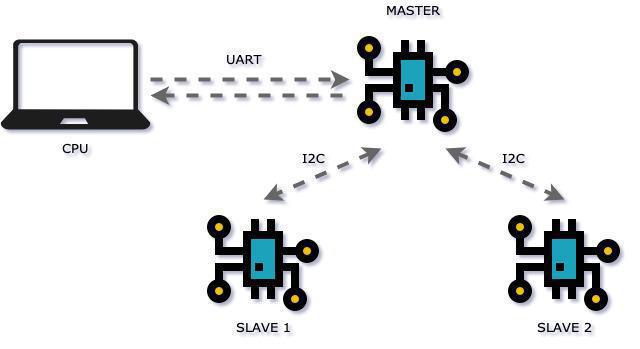
For the individual assignment I decided to use 2 communication protocols, the UART and the I2C.
The idea is to use the UART communication to connect the PC to the master card, and use the I2C communication to establish communication between the master card and 2 slave cards, with the purpose of being able to choose which to communicate by specifying which address to send the message. In this way I managed to create a network that merges 2 types of communications, UART and I2C.
For the group assignment, which was to send a message between 2 projects, I chose to work as a team with my partner Letty, however, we did not have the necessary cards to carry out this task, so we decided to generate a serial production of many cards, so we designed a card with the minimum necessary to make communications.
This helped us both for the group and individual assignment, for the lack of cards.
The idea to send a message from my computer to my partner's, was to join my network created with yours, through the UART protocol. The following image illustrate this idea.
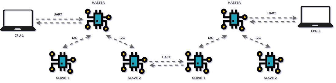
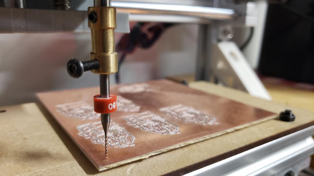
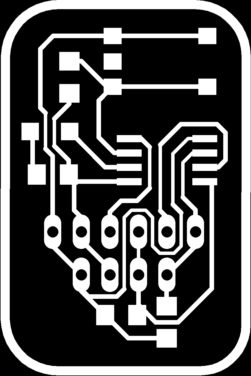
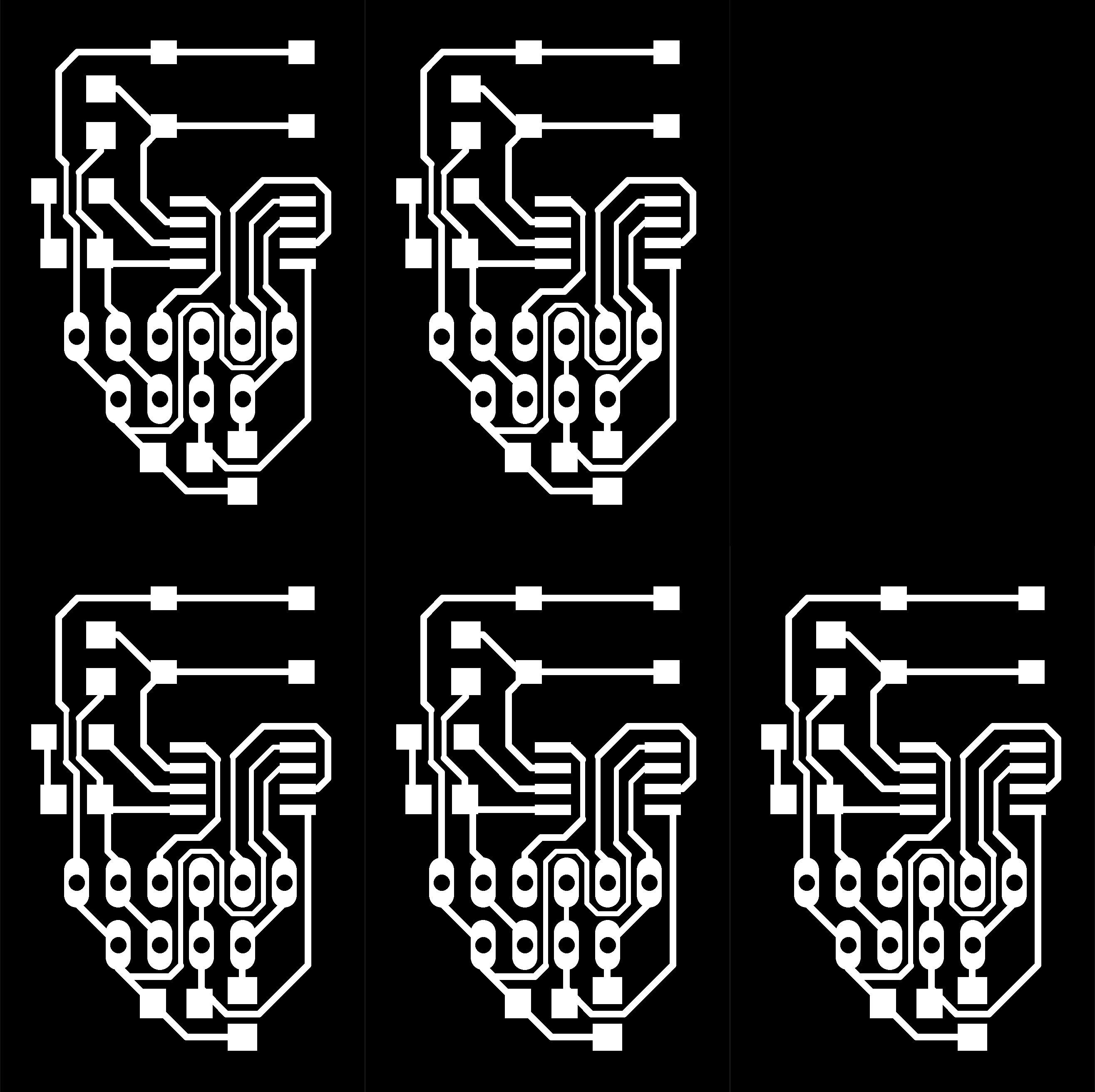
In this practice we had an unfortunate problem, in order to make the proposed network we needed more cards, because, until now, the cards we had were insufficient. To solve this problem, I decided to design a replicable card to mass produce (so to speak), in this way I could fulfill individual and group practice by cutting several cards.
 19.26.06.png)
 19.26.16.png)
With this design, I joined several in Photoshop and then load them into fabmodules to generate the files to record and cut the pcb in the minimill.


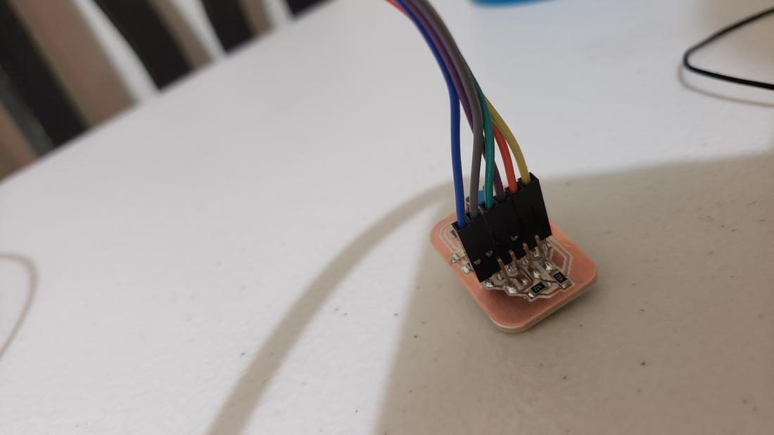
Finally I soldered the components and tested the cards. It is worth mentioning that only the cards are designed and each one is in charge of welding and testing their cards.


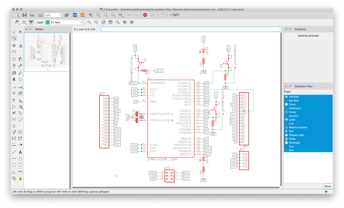
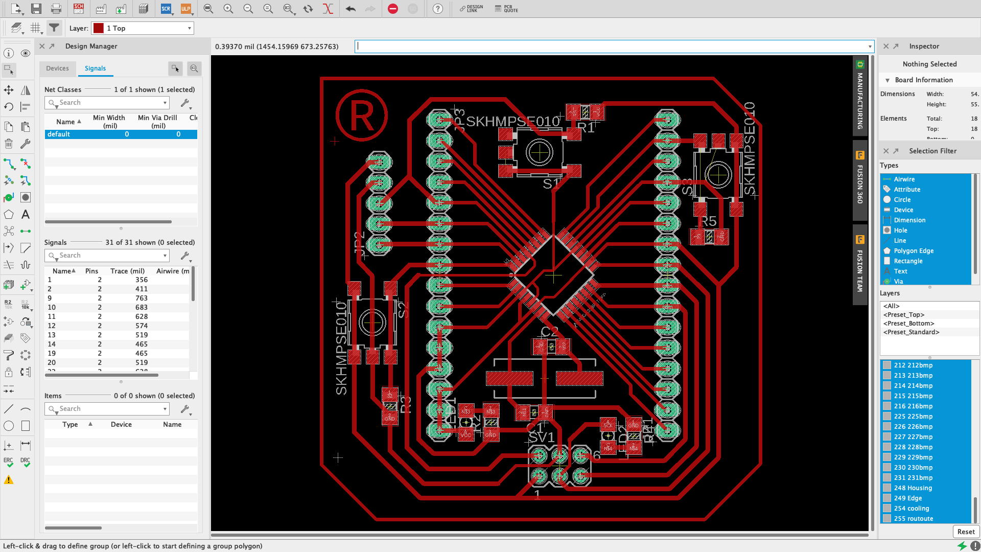
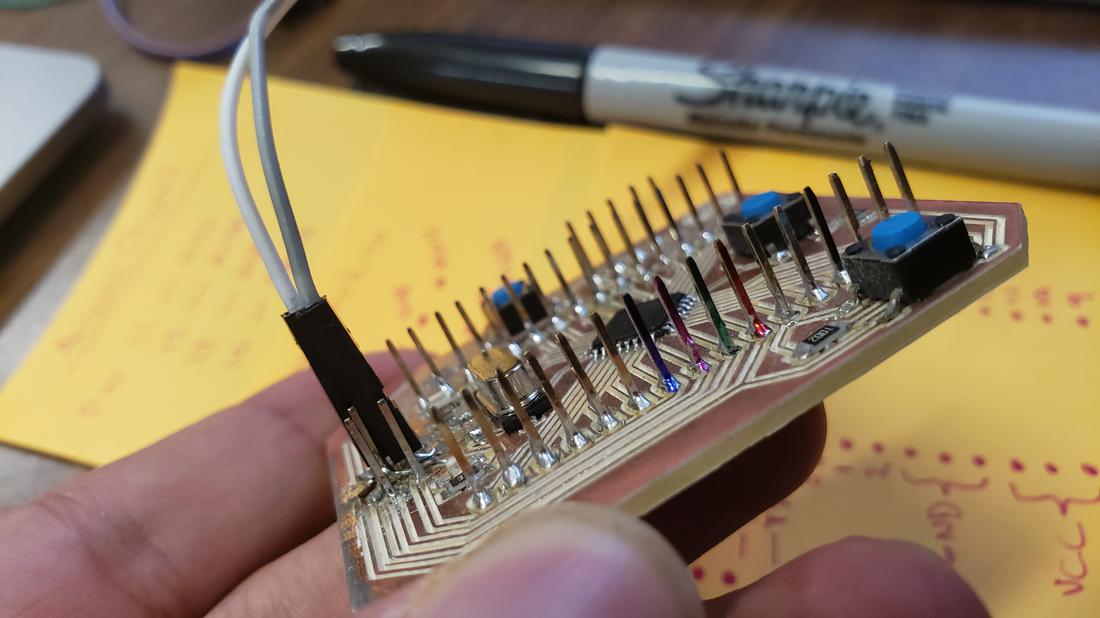
There was a problem, the pins of my previous cards would not give to maintain several slaves, besides that to use the serious communication and i2c at the same time in an attiny was complicated, since both are by software reason why they caused conflict between them. For this reason I decided to design a larger board, with the Atmega 328P microcontroller.

While the pcb cards were generated by the cnc minimill, I tried to make an i2c communication using two arduino cards, in this way I could go testing the functioning of this communication.
In order not to get lost among so many pins I decided to paint some important pins that I would use.
With the pcb card created with the atmega 328P, I had to load the bootloader to convert it to arduino. It is enough to connect it to the computer USB port and press the "Upload" icon to start a process that transfers your sketch into the Flash memory of the microcontroller.
The behaviour described above happens thanks to a special piece of code that is executed at every reset of the microcontroller and that looks for a sketch to be uploaded from the serial/USB port using a specific protocol and speed. If no connection is detected, the execution is passed to the code of your sketch.
This little (usually 512 bytes) piece of code is called the “Bootloader” and it is in an area of the memory of the microcontroller – at the end of the address space - that can’t be reprogrammed as a regular sketch and had been designed for such purpose.
Remember select "Arduino as ISP" from Tools > Programmer and after run Tools > Burn Bootloader
 0.46.15.png)
After burning the bootloader, I had many problems with this card, since I could not program it, so I had to verify the pins and connections and continuity with a multimeter. After looking for the problem for a while, I realized that a button was causing problems, so I decided to remove it, since it was just an extra button.
With my new atmega card now ready to be programmed, I decided to make the first part of the UART network by connecting this card with the small attiny card.
As mentioned above, the UART communication only requires two connections, TX -> RX and RX -> TX.
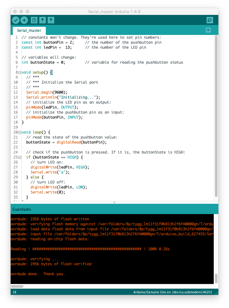
The master card that I chose was the atmega card I made, where I only declared the pins of the button and led, since the idea was that by pressing the button, it would turn on a led and turn on the led of the slave card. On my master card I was able to use the Serial library without problems, as the Atmega 328P microcontroller allows.
The data rate in bits per second (baud) for the serial data transmission is set to 9600 baud and then make a simple screen printing indicating the initialization of the serial.
In the loop function I put an int variable to know the state of the button which, by means of a decision if I ask if the status of the button is high or low, if it is high I write in the serial the char 'a', in case otherwise I write a 0 and turn off the led.
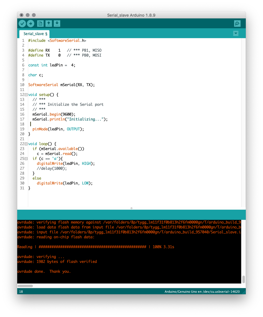
For the slave card, I had to use the SoftwareSerial library, due to the limitations of the Attiny85 microcontroller.
The Arduino hardware has built-in support for serial communication on pins 0 and 1 (which also goes to the computer via the USB connection). The native serial support happens via a piece of hardware (built into the chip) called a UART. This hardware allows the Atmega chip to receive serial communication even while working on other tasks, as long as there room in the 64 byte serial buffer.
The SoftwareSerial library has been developed to allow serial communication on other digital pins of the Arduino, using software to replicate the functionality (hence the name "SoftwareSerial"). It is possible to have multiple software serial ports with speeds up to 115200 bps. A parameter enables inverted signaling for devices which require that protocol.
In this code, I defined the RX pins to pin 1 (PB1, MISO) and TX (PB0, MOSI) and assigned them to the mSerial variable of type SoftwareSerial.
In the setup simply initialize the mSerial and assign the pin of the led in output.
In the loop function I ask if the mSerial is available then I read the buffer and assign it to a variable, in this case of type char.
If this variable matches 'a' then I turn on the led of this card, otherwise I turn off the led.
In the following video the result of UART communication is shown.
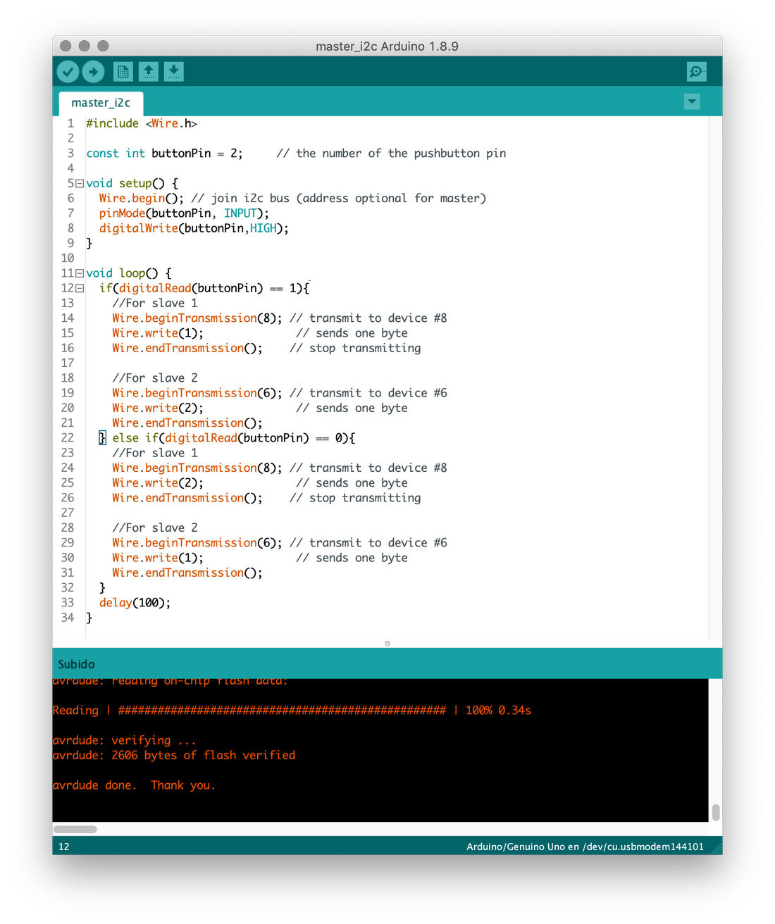
For I2C communication, my network consists of 1 master and 2 slaves. The master card is the atmega and the slaves are the attiny's cards, each assigned to an address.
In the master I added the Wire.h library that allows communication with I2C.
In the setup, initialize the Wire library to join the I2C bus as a master.
If you specify the address it will be like a slave, but if you do not specify it, it joins the bus as a master.
In the loop function, I ask for the state of the button, if it is in 1 start the transmission to the slave with address 8 and write a 1 on the data bus and end the transmission, then start another transmission but now to the slave with address 6 and I write a 2 on the data bus and in the same way I finish the transmission. Otherwise, when the button is set to 0, I do the opposite, to slave 1 I write a 2 and slave 2 I write a 1.
Finally I put a small delay to not send as many bytes when pressing the button.
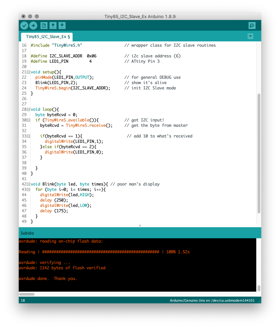
For the code of the slaves, I could not use the same library of Wire.h, since in the same way as with the Serial library, the limitations of an Attiny85 microcontroller do not allow it. However, its version exists through software, in such a way that it uses the TinyWireS.h library, which you can download from the files section, on this page.
In the variable I2C_SLAVE ADDR defined the address of the slave and in the varable LED1_PIN the pin of the led of the attiny card.
In the setup set the mode of the LED pin and call the function Blink, which receives 2 parameters, the first indicates the led and the second is an integer that determines how many times the LED flashes.
Then I initialize the TinyWireS library to join the I2C bus as a slave.
In the loop function, I ask if the communication is available to receive the data bus. If the byte is equal to 1, then turn on the led, otherwise turn it off.
For the other slave is the same code, it is only important to change the address, in this case my slave 1 its address is 0x08 and slave 2 is 0x06.

The files //
Below you can find the download links of the original files created for this week.
- { attinys2_completo.png }
- { attinys2_grabado2.png }
- { attinys2_corte2.png }
- { attinys2.sch }
- { attinys2.brd }
- { electronicproduction.brd }
- { electronicproduction.sch }
- { mimaster.ino }
- { mislave.ino }
- { ArduinoISP.ino }
- { Serial_master.ino }
- { Serial_slave.ino }
- { master_i2c.ino }
- { Slave1_i2c.ino }
- { Slave2_i2c.ino }
- { TinyWireS library }