14 + 16/ mechanical + machine design
We made a plotter that can draw routes on maps! A "HOW TO GET ALMOST ANYWHERE" machine.
1. group documentation page
2. individual contribution
← previous
→ next
⋯ assignment list
🏁/ final project
Group project:
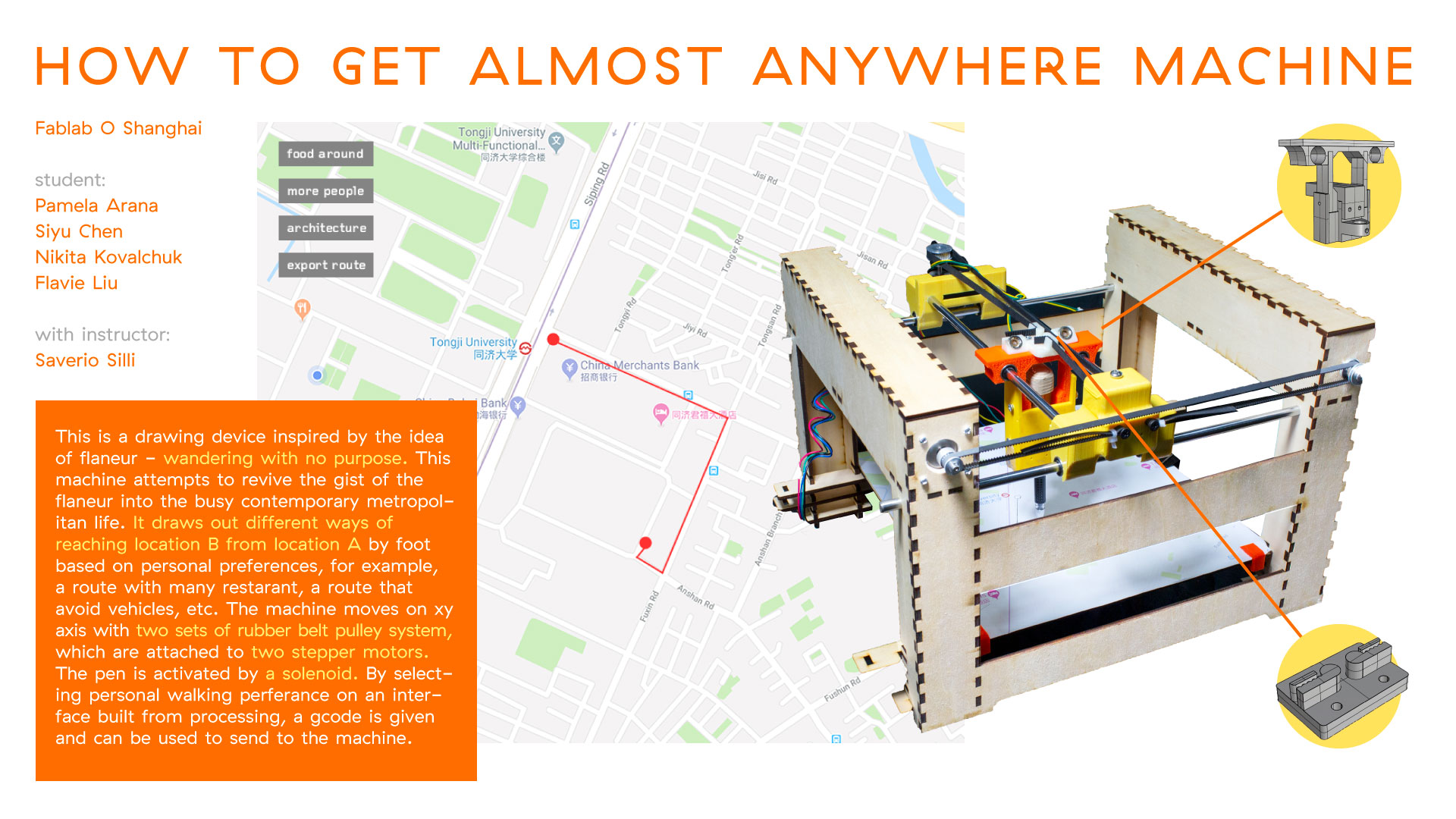
Our group decided on making an machine that can generate routes base on custom input and draw the trace on a physical map.
The complete project documentation is on the group page.
Here is the link to final video.
For the hardware, we used CNC shield with Arduino UNO as drive, with two step motors for X and Y axis, and one solenoid for Z axis. Notice on the image below the heads inside the red circle will need to be connected using jumper parts for microstepping.

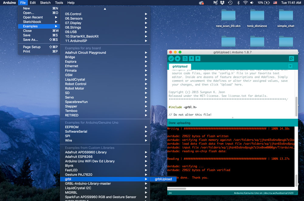
We need to use GRBL for Arduino to control the motors. "Grbl is a free, open source, high performance software for controlling the motion of machines that move, that make things, or that make things move, and will run on a straight Arduino." Here are the steps:
- 1. Download grbl zip folder from master branch on github.
- 2. Unzip the folder. In Arduino IDE, import library by adding the grbl subfolder inside the grbl-master folder.
- 3. Restart Arduino, open the grblupload example sketch and upload it onto Arduino UNO. No need for any code modification.
Then we use Universal Gcode Sender to send gcodes to the motors. UGS is "a full featured gcode platform used for interfacing with advanced CNC controllers like GRBL and TinyG." Below are the steps:
- 1. Download and install the new version of Java.
- 2. Download and extract the UGS Platform from this page.
- 3. Go to the ugsplatform/bin directory.
- 4. On Mac OSX run ugsplatform.
Detailed instruction on UGS platform can be found here.

Since we got some previously-made structures in our lab, we assembled them, connected the motos onto the shield, manually clicked X and Y in UGS platform to send signals. In the following video you can see the motors are working with the temporary structure!
Individual contribution
I mostly worked on the software part, generating and sending gcodes to move the plotter.
We need to generate gcodes specifically for our project, which are the codes to draw routes.
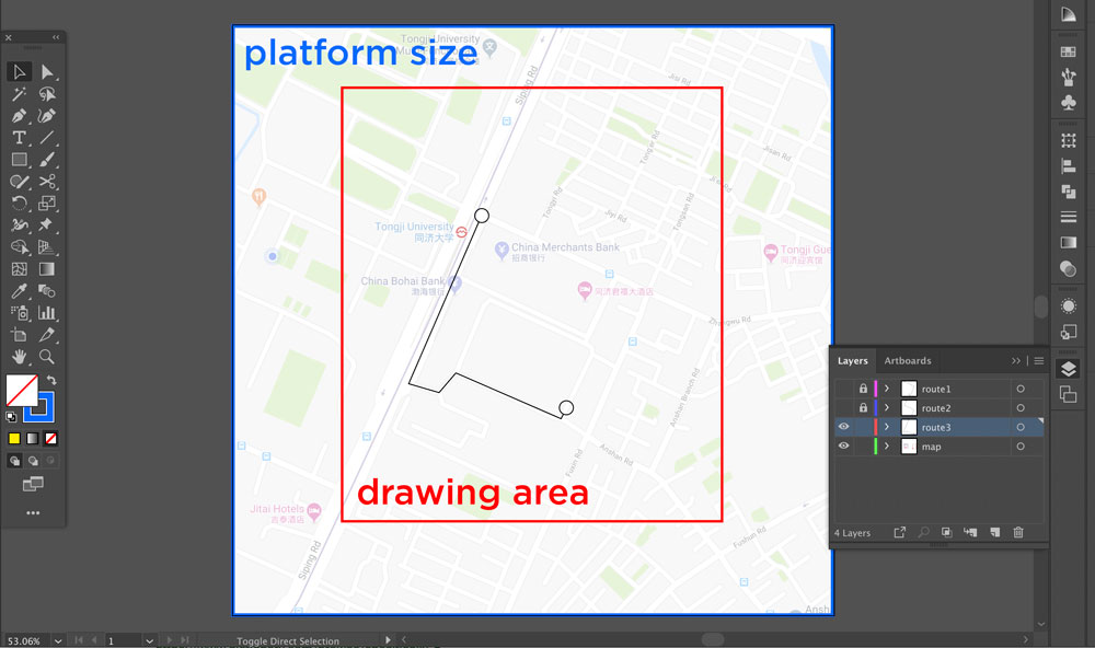
First in Adobe Illustrator, I imported the map in the background as reference. Then I measured the drawing area of our machine structure and drew routes inside the area. I exported the routes seperately as .svg files.
Then I imported the .svg files into Inkscape and used the gcodetools extension to export gcodes. There were problems with the new version inkscape on Mac. After testing with different versions, here are the steps that make it work for me:
- 1. Download very old version of inkscape. I use 0.91.
- 2. Download gcodetools extension from internet and copy the files inside into the share folder under inkscape.
Here is the video demonstrating the process in inkscape.
The file exported from the inkscape has no extension. You can manually rename it with .nc extension and open it with any text editor.
Since we are using solenoid instead of servo motor for Z axis, the number associated with Z does not matter to us. To controll the solenoid, we need to manually put in the command to ask the solenoid to lift up or push down. M3 for pen up and M4 for pen down.

There should be a way to change this command with post-processor. I will explore if I have more time. Here is a link I can check out.
Open UGS platform, import the gcode file.
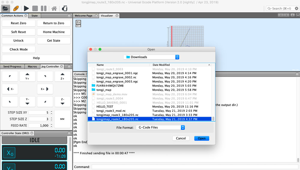
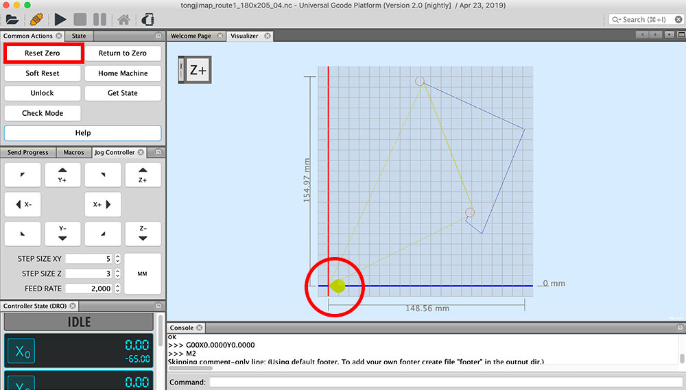
It is important to check and set the 0 point for X and Y, especally after disconnecting and reconnecting the motors. The 0 point position should match with the original point set in inkscape.
Before you start drawing with your machine, you need to check and modify the GRBL parameters by typing in "$$" in the command field. In our case, since we are using different size pulleys connecting X and Y motors, we need to change the step size accordingly.
$0 = 10    (step pulse, usec)
$1 = 25    (step idle delay, msec)
$2 = 0    (step port invert mask:00000000)
$3 = 0    (dir port invert mask:00000000)
$4 = 0    (step enable invert, bool)
$5 = 0    (limit pins invert, bool)
$6 = 0    (probe pin invert, bool)
$10 = 3    (status report mask:00000011)
$11 = 0.010    (junction deviation, mm)
$12 = 0.002    (arc tolerance, mm)
$13 = 0    (report inches, bool)
$20 = 0    (soft limits, bool)
$21 = 0    (hard limits, bool)
$22 = 0    (homing cycle, bool)
$23 = 0    (homing dir invert mask:00000000)
$24 = 25.000    (homing feed, mm/min)
$25 = 500.000    (homing seek, mm/min)
$26 = 250    (homing debounce, msec)
$27 = 1.000    (homing pull-off, mm)
$100 = 100.000    (x, step/mm)
$101 = 40.000    (y, step/mm)
$102 = 5.000    (z, step/mm)
$110 = 1000.000    (x max rate, mm/min)
$111 = 1000.000    (y max rate, mm/min)
$112 = 500.000    (z max rate, mm/min)
$120 = 10.000    (x accel, mm/sec^2)
$121 = 10.000    (y accel, mm/sec^2)
$122 = 10.000    (z accel, mm/sec^2)
$130 = 200.000    (x max travel, mm)
$131 = 200.000    (y max travel, mm)
$132 = 200.000    (z max travel, mm)
The plotting route in UGS platform looks like:
The machine draws precisely :D
I also made a demo for interface with processing showing how the customized input will work. We may keep develop this idea and build it out with javascript one day.
Useful links:
(Updated 05.22.2019)