10/ input devices
This week is about testing input devices, getting more advanced in electronics, making as many possibles mistakes as I may and learning from them :/
1. making FLAVINO
2. Input sensor tests
3. Probe an input device's analog levels and digital signals
← previous
→ next
⋯ assignment list
🏁/ final project
Making FLAVINO
This week we are making microcontroller board again. We need to add a sensor to it and use the sensor to measure something.
For the board design, our instructor Saverio encouraged us to make our own versions of Arduino, to better understand how the electronics work and also to have the flexibility of connecting the board with different sensors. For me the board will be Flavino.
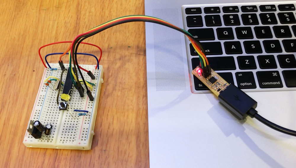
We started replicating Arduino on a breadboard with the same ATmega 328P chip. Since we have used ATmega 44 and 45 in the previous two PCBs, we have a clear understanding of the process of programming the chips and their limit with serial communication. It is time now to take a step further and switch to a more advanced chip. Breadboard is not something of Fab Academy's style, but it helps lay components and connections out in a clear and efficient way.
Link to Building an Arduino on a Breadboard guide
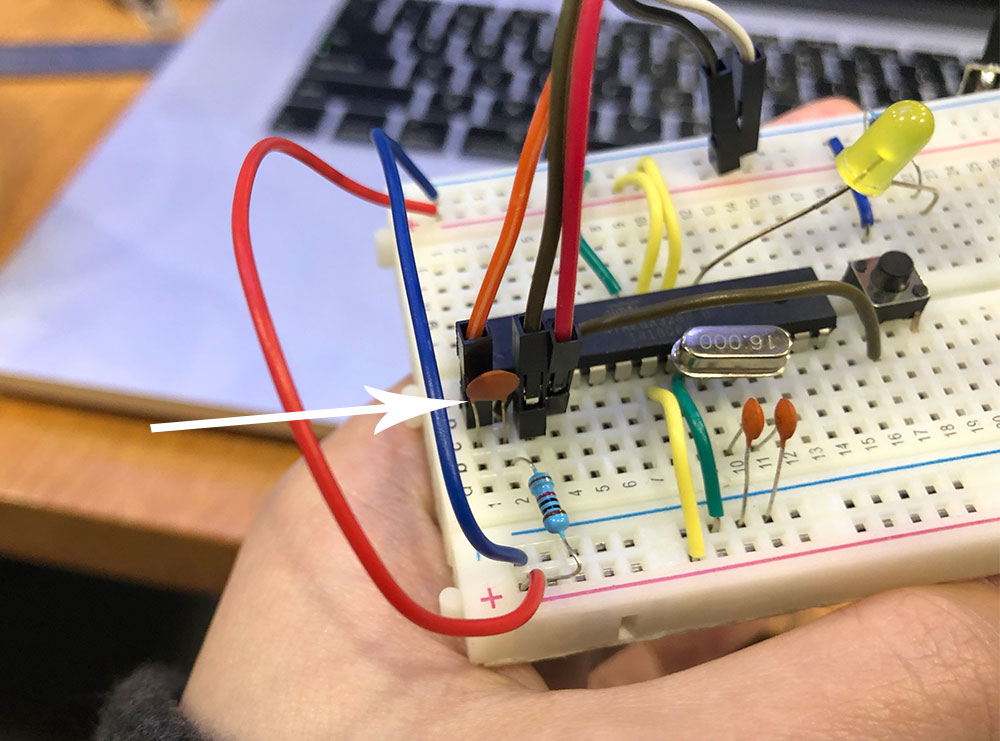
One thing we noticed was that the board was able to burn bootloader through ISP but it could not upload programs using FTDI cable. This is caused by the difference in communication speed. We need to slow the speed down by adding an extra 0.1uF capacitor to the reset pin on ATmega and connect the FTDI reset pin after the capacitor.
Here is the list of components I used on my breadboard:
- – ATmega 328p MCU
- – 22 AWG wires
- – 7805 Voltage regulator
- – 2 10uF capacitors for the Voltage regulator
- – 1 10kOhm resistor between RESET and VCC
- – 1 LED
- – 1 220Ohm resistor for LED
- – 16 MHz clock crystal
- – 2 22 pF capacitors for the crystal
- – 1 button
- – 1 0.1uF capacitor next to RESET
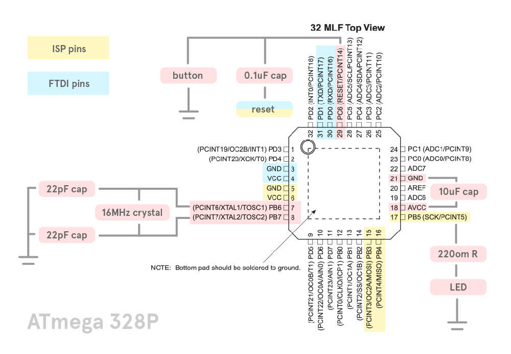
This is how the connections on the breadboard get translated into a map. I find this drawing diagram method helpful to understand how different parts work and useful as a reference for designing the routes in Eagle.
For pins' functions and more info refer to ATmega 328p datasheet.
Before I started with Eagle, I checked both Fabkit and Sashakit's design. I realized that the ISP and FTDI pin headers could be seperated instead of being a group of six pins next to each other, which could help simplify the routes a lot.
The layout of the board roughly follows the diagram I drew.
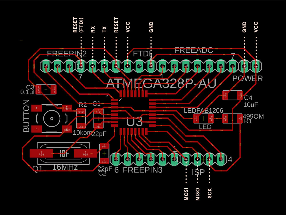
This is the final schematic for Flavino 1.0.
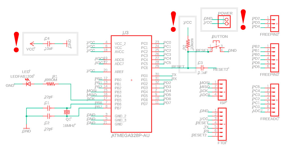
There has been all sorts of mistakes and countless times of modifications. Some main mistakes I made are marked with "!" above and can be found in the physical productions below:
- 1. forgot to connect reset to VCC with an 10k om resistor
- 2. forgot to add a 10uF capacitor between VCC and GND
- 3. forgot to add extra VCC and GND pin headers so once the board is powered it will not be able to power up other components

Other problems I had were due to my poor soldering skill. I melted some plastic parts of female pin headers when soldering them and causing the connection to be loose. Or I was not very good at controlling hot air gun and almost melted a row of pin headers...
Sometimes although all connections are working according to the multi-meter, it can be helpful to add a little bit more solder to the joints, or use the iron to reheat, melt the solder blob and stable the connection to traces again. The 0000x0 check the connection error message I got during bootloading went away after Saverio helped me go through the solder enhancing process :D
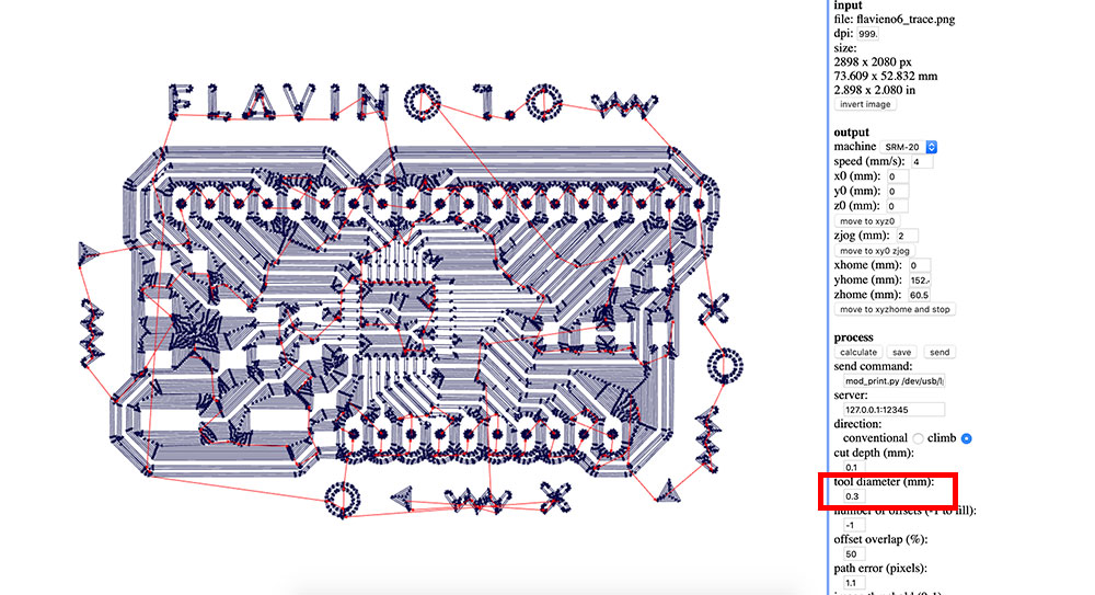
While generating tool paths in fabmodule, I encountered the issue that the spacing between ATmega legs are less than 0.4mm, so the 1/64 end mill would not be able to go through and there would be no milling trace in between. I got warnings when I checked the design rules in Eagle board view. My solution was to manually modify the png image, open up the space between legs by drawing 0.4mm wide black rectangles in Adobe Illustrator. Then in fabmodule settings I changed the tool diameter to 0.3 to make sure there would be paths in between ATmega legs.
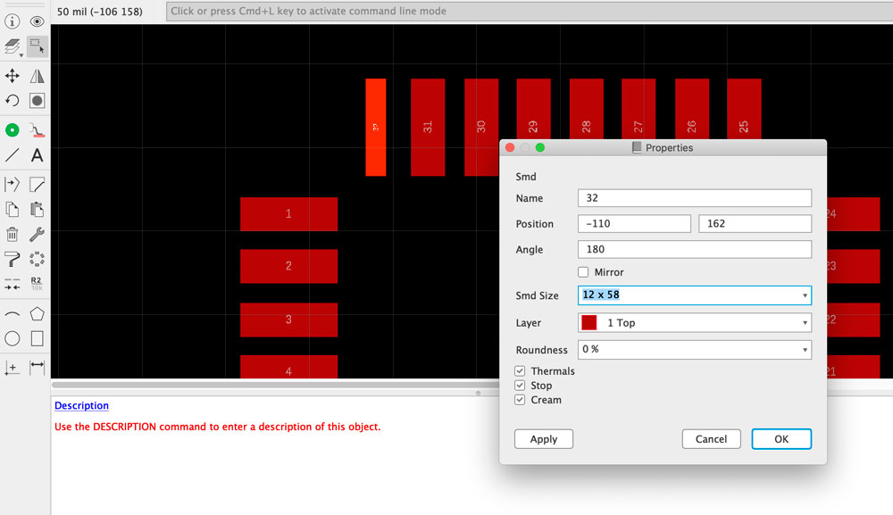
During this week's regional review Rico from Fab Lab Kamakura showed us the trick to change the parameters of ATmega328p's pads so we could thin the pads and open up more space for the traces. It is possible to customize the footprints of SMDs or even draw your own components from scratch. Here is a more detailed eagle footprint design tutorial from sparkfun for further reference.
After the board is soldered and proved ok by multi-meter, I connect it to my FabISP and to my laptop.
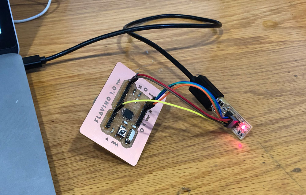
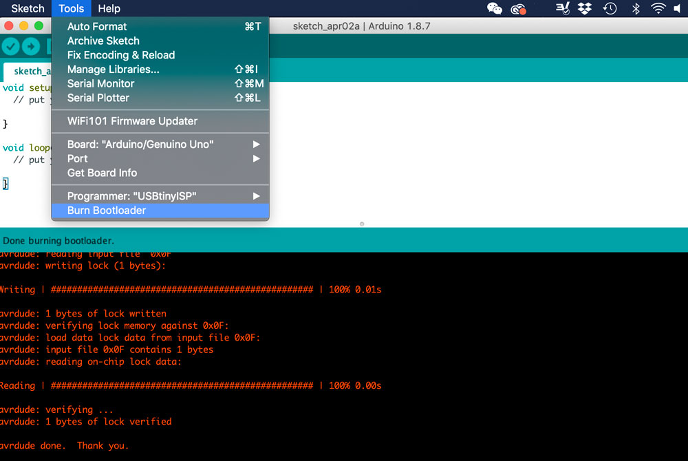
Open Arduino IDE, under Tools select "Arduino/Genuino Uno" for boards and "USBtinyISP" as programmer, run "Burn Bootloader". If there is no connection issues, the board is now bootloaded :D Flavino 1.0 can say goodbye to ISP and it will use FTDI cable for communication from now on.
I tried upload a simple blink program to Flavino and it started to blink :D

↓ download files:
Input sensor tests
To get a sense of how sensors work, we first picked the ones that we might use in the final project and tested them with breadboards.
One sensor I picked was a touch sensor. It comes with a piece of aluminum foil, a single touch pad that senses the electrical capacitance of the human body, and a few connection pins. It inputs high or low value, and works same as a switch.
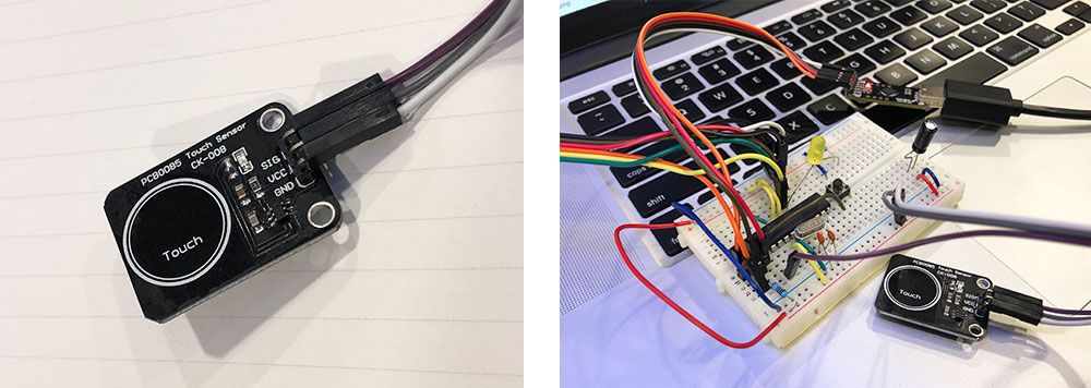
Below is my very simple arduino code making LED light up or turn off when touching the sensor. It works fine but I wish there could be more types of status for different ways of touching.
void setup() {
pinMode(2, INPUT);
pinMode(LED_BUILTIN, OUTPUT);
Serial.begin(9600);
}
void loop() {
if (digitalRead(2) == LOW){
digitalWrite(LED_BUILTIN, HIGH);
delay(100);
Serial.println("Sensor is touched");
delay(100);
}
if (digitalRead(2) == HIGH){
digitalWrite(LED_BUILTIN, LOW);
delay(100);
}
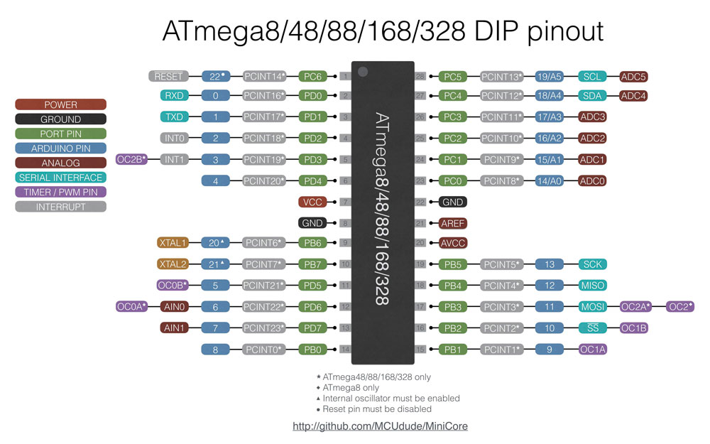
}It was helpful to check the pin out map for ATmega328p while programming in Arduino IDE:
The other sensor I tried was an Ultrasonic distance sensor. It uses sonar to calculate its distance to an object like how the bats do. The sensor emits an ultrasound at 40000 Hz which travels through the air and if there is an object or obstacle on its path the sound pulse bounces back to the module.
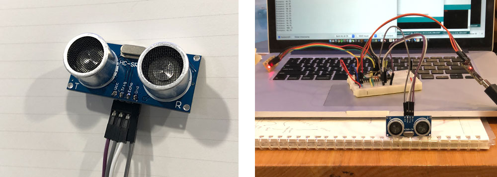
This sensor is cool because its input can be a range of changing values rather than just high/low status. I used a ruler to test its sensing precision and the result was very close to the actual distance.
/*
 * HC-SR04 example sketch
 *
 * https://create.arduino.cc/projecthub/Isaac100/
 getting-started-with-the-hc-sr04-ultrasonic-sensor-036380
 *
 * by Isaac100
 */

const int trigPin = 8;
const int echoPin = 7;

float duration, distance;

void setup() {
  pinMode(trigPin, OUTPUT);
  pinMode(echoPin, INPUT);
  Serial.begin(9600);
}

void loop() {
  digitalWrite(trigPin, LOW);
  delayMicroseconds(2);
  digitalWrite(trigPin, HIGH);
  delayMicroseconds(10);
  digitalWrite(trigPin, LOW);

  duration = pulseIn(echoPin, HIGH);
  distance = (duration*.0343)/2;
  Serial.print("Distance: ");
  Serial.println(distance);
  delay(100);

if (distance < 10){

 digitalWrite(LED_BUILTIN, HIGH);
  delay(10);
}
if (distance >= 10){

 digitalWrite(LED_BUILTIN, LOW);
  delay(10);
}
}
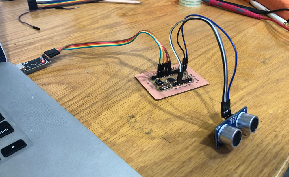
After I made Flavino out, I connected it to the distance sensor and ran the same program above. It read distance well although the tiny LED was not so obvious as the large one on breadboard :D
Group assignment
For group assignement this week we need to use an oscilloscope to read input devices' analog and digital signals.
We connected the oscilloscope to Flavino and made several tests. Pamela from our lab made very detailed documentation:

We first tested blink signal, by connecting the alligator clasp of oscilloscope to GND and SCK (LED pin). The oscilloscope generated constant square waves switching between low point(0) and high point(5V) with regular time intervals as the LED blinked.
We then connected a potentiometer to the board. We read analog input signal from Out pin on the potentiometer (blue line), and digital signal from Rx pin on the board (yellow line) at the same time.
While tuning the knobs for the potentiometer, the analog signal (blue line) remained as roughly a flat line and moved up and down as a whole; The digital signal (yellow line) received signal impulse in set delay time interval, and the length of the signal impulse varied according to the input value of the potentiometer. COOL!

(Updated 04.03.2019)