Week 15: Mechanical and machine design
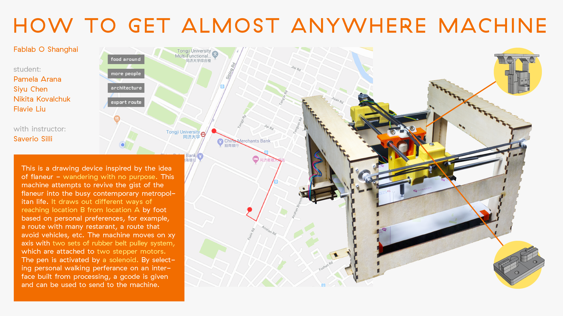
The How To Get Almost Anywhere Machine
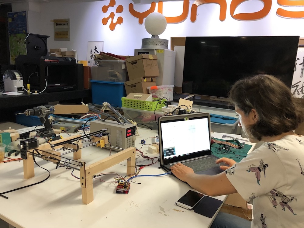
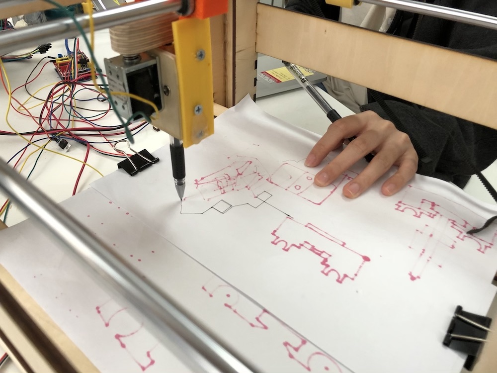
The How To Get Almost Anywhere Machine is a drawing device inspired by the idea of flaneur - wandering with no purpose. This machine attempts to revive the gist of the flaneur into the busy contemporary metropolitan life. It draws out different ways of reaching location B from location A by foot based on personal preferences, for example, a route with many restarant, a route that avoid vehicles, etc. The machine moves on xy axis with two sets of rubber belt pulley system, which are attached to two stepper motors. The pen is activated by a solenoid. By selecting personal walking perferance on an interface built from processing, a gcode is given and can be used to send to the machine.
Designers: Pamela Arana, Siyu Chen, Nikita Kovalchuk, Flavie Liu
Instructor: Saverio Silli
click HERE for more details and group contributions to the project
Conceptual Development
We had a brainstorm session with Simone Rebaudengo (a product and interaction designer based in Shanghai) and Travis Russett (former Fab Academy student from Fab Lab O). With a diverse group of members in our brainstorm session, we came up with many ideas, including making food related machines, machines that draws your heart beat or noise level, fan dancing machine, cricket machine, etc. However, none of the ideas were very specific.
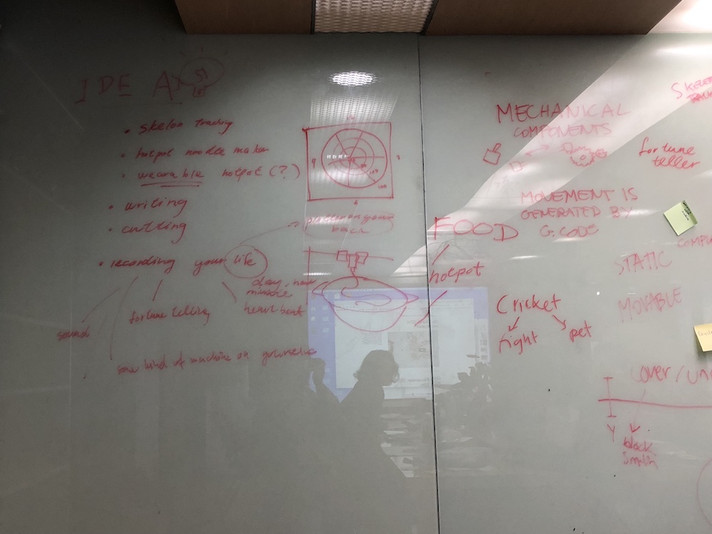
While attending Fab Asian Network 5 in Seoul, we thought machine that tracks your day has a strong presence during our brainstorm session. As none of us had experience in machine making, starting with a plotter structure is more practical. It also gives us a limitation that we can play with. We ended up with making a walking path plotter on a paper map. We are interested in different ways of reaching location B from location A based on preferences. For example, a route with restaurants would give a route, a route that avoids noise would give another route.
In a busy metropolitan like Shanghai, we often move between locations within a familiar route in order to save time. This route bot attempts to revive the gist of the flaneur - wander with no purpose - in the busy contemporary lifestyle.

Prototyping
Initial Modeling
In order to understand how a xy plotter works, first we looked at the structures of existing plotter. We have one structure that moves in one axis. The stepper motor was connected to a threaded rod, with its pitches counting as steps. We uploaded GRBL, an opensource G-code interpreter for Arduino devices. A CNC shield was then pinned into the Arduino UNO board we were using. This GRBL compatible CNC shield can be used to support X, Y, Z and full axis. It runs on 12-36V DC, which means we had to plug the shield with a power supply. For each axis, there are two end stops, which allows the CNC to plot within the given area. Stepper Motors can be connected with 4 pin molex connectors or soldered in place.

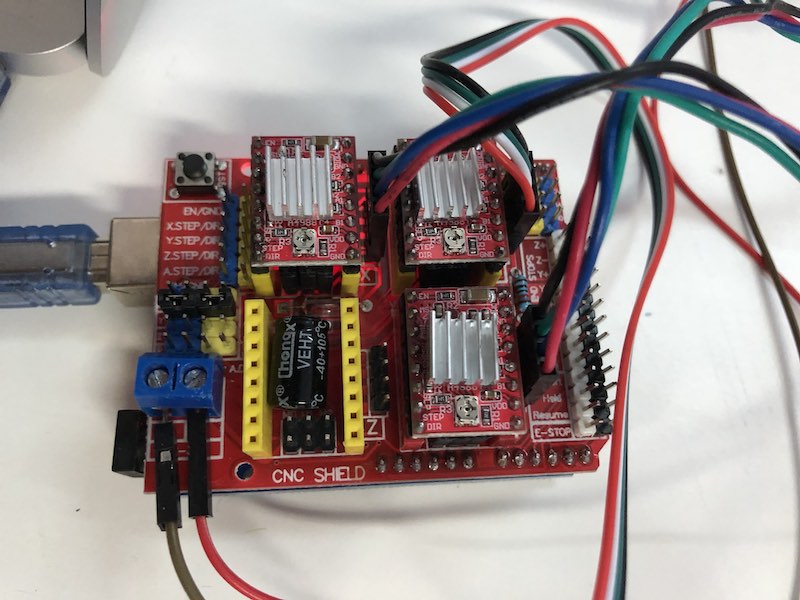
After we uploaded GRBL and connected the CNC shield, we used a Java based software Universal Gcode Sender to activate the stepper motor. As a recap from the previous week, a Gcode (geometric code) is a numerical control programming language that is used to instruct where and how a machine moves. During 3D printing week, the code we’ve generated using Cura from our CAD model instructs the 3D printer to move in X, Y and Z axis. It is also referred to as the “path” for the machine movement. On THIS website, there is a list of Gcode commands. Some of the most important commands for activating machine movement are:
G20/G21 set units to inches/millimeters *THIS IS VERY IMPORTANT! Always put it as the first line
G0 rapid move (jog)
G1 linear move
G90 relative position
G91 absolute position
F feedrate
E extrusion (for machine with extruding function e.g. 3D printers)
And of cause, for testing the motor you can type something as simple as
X10 Y10.
Understanding the basics, we took apart a vertical 3d printer at our lab and put it in place to function as a XY plotter.
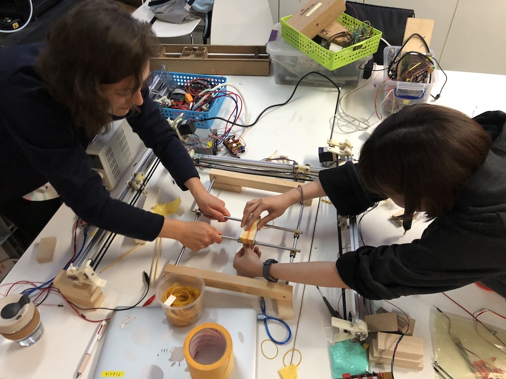
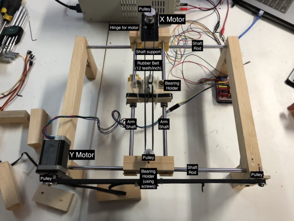
Second Model
Having built the prototype, we had a better understanding on how a plotter works. This prototype is closer to how our final plotter would look like. We have one motor for each axis, whereas earlier the third motor was connected to another motor using a jumper. We used a rubber belt with the pulleys. We used some of the bearing holders from the 3D printer. And thanks to Saverio’s shaft support, we could combine the pulleys with the shaft rod.


Final Design
From the second model, we understand the design for each component on a plotter better, which allows us to divide the task for building the final machine among us:
●Pamela - Structure
●Nick - Shaft support for X and Y axis
●Siyu - Shaft support for solenoid, pen holder
●Flavie - Coding and programming
My Task: Pen Holder and its Shaft Support
I worked on the hinges for the solenoid and pen holder. Since we have limited time to work on the mechanics for the Z-axis and the servo motor plugin with Inkscape worked on none of our computers worked, we decided to use a solenoid to activate the pen. In the prototype, Nick made a wooden mechanism to connect the solenoid with the pen so that the pen can be pushed down when a writing command is given. I decided to keep the wooden structure, since the heat from the solenoid might melt a polymer-based material like PLA. I would need to design a part that attaches the pen and solenoid holder with the shaft rod. The part would also need to bear the weight of the solenoid.
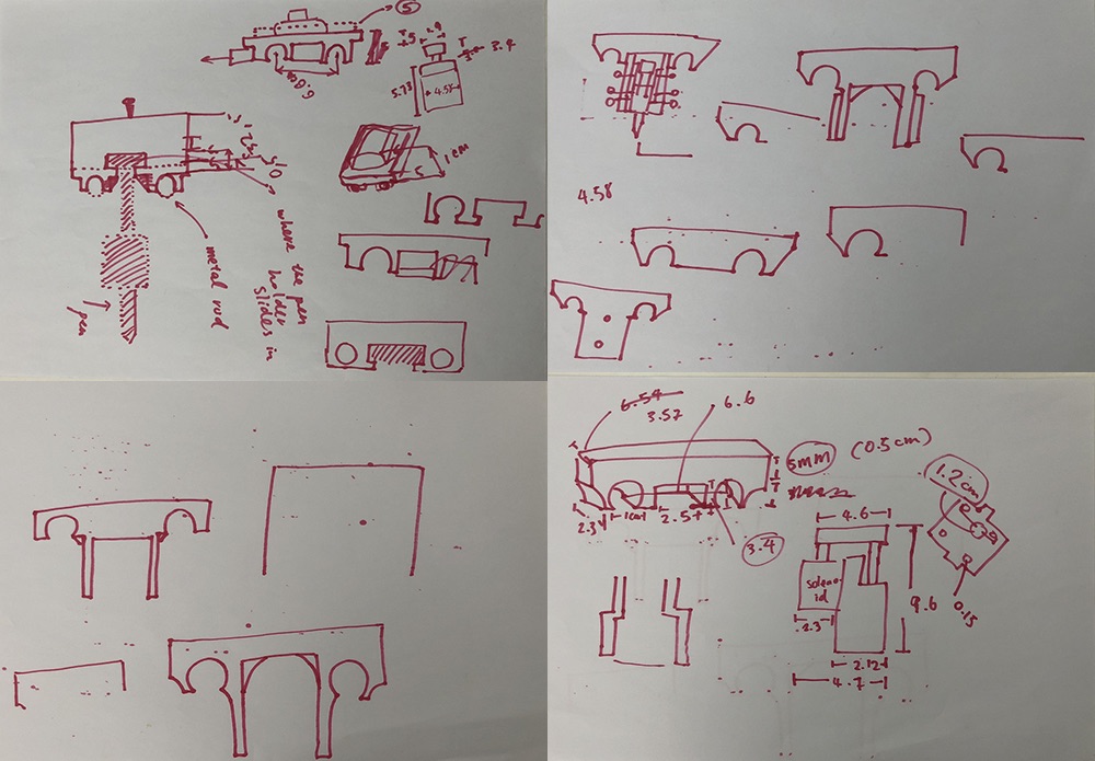
Since Nick was designing the shaft supports for the X axis, we had to agree upon some of the measurements our parts share, including the distance between the center of the shaft rod circle, the height of the support, etc. Afterward, I began to develop the part:
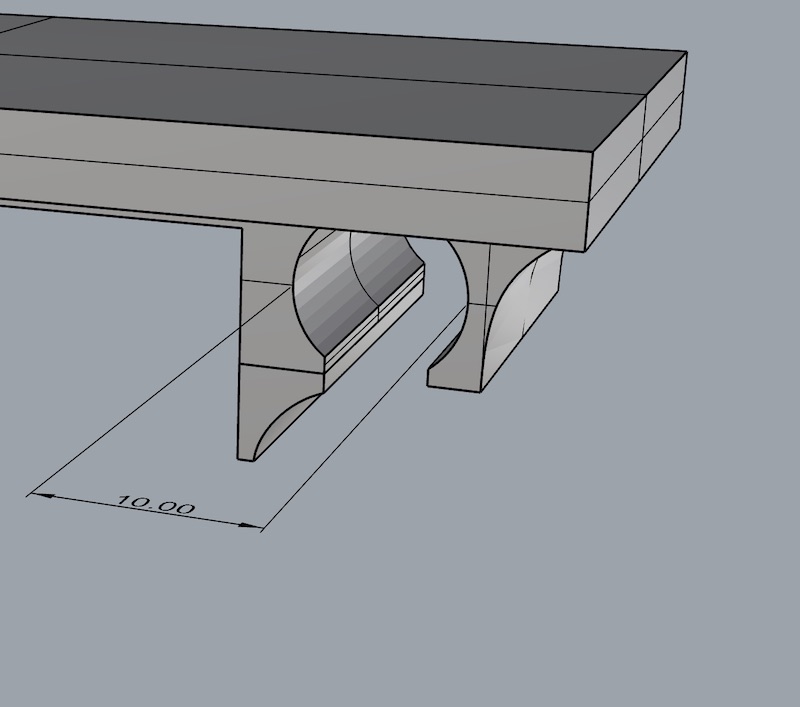

To ensure the parts are solid enough as a support, I adjusted the wall thickness of the components to 2.5mm. Here is the setting used to generate the gcode on Cura:
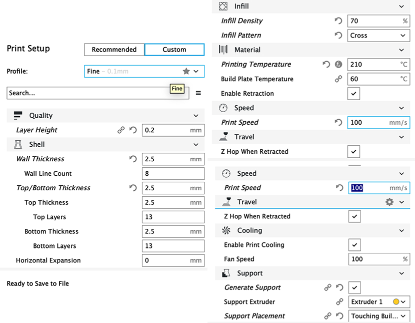
Two parts of the shaft support fits together nicely, and also fits the pen holder we buult earlier. The part also matches with the dimension of the support Nick designed. NOTE: The upper part (orange component in the image) stopped printing around 70%, I tried to resent the print twice with once on a different printer, it always stop in the midway. Although the component works, but I will need to check the gcode file.
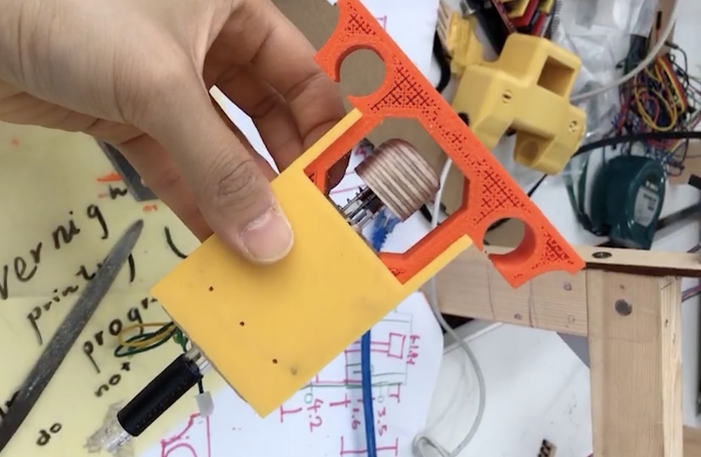

Here is the shaft support in use:
FILES FOR SHAFTSUPPORT: shaftsupport_partA.stl, shaftsupport_partB.stl
However, attaching a shaft support onto our current pen holder that is designed for one type of pen only is not a sustainable solution. We decided to redesign the pen holder to fit in pen with different dimensions. I looked at designs for pen holder activated by servo motor or Z-axis, many of them fixes a pen into the holder with a adjustable nail like fixing an endmill onto a milling machine. Since our pen holder is activated by a solenoid, we need an additional part that can be pushed by the solenoid. We also need to have a part to attach the solenoid. Since solenoid heats up, we will need to use a piece of wood for the solenoid to sit, and to attach that piece of wood onto the PLA based component. Here is the design I came up with:

FILES FOR PENHOLDER: penholder_partA.stl, penholder_partB.stl, penholder_partC.stl


However, this design did not work for several reasons. Firstly, the print is shrinked by at least 0.3mm of its original dimension in the CAD file. The gap in between the solenoid and the component is not big enoug for putting a piece of wood that goes in between. I did not take into account the extra 1 mm from the screws of the solenoid. It was also impossible to make the rail and rail holder (as seen in the photo on the right) 90 degree. The holes for drilling screws on the rail holder was places near the rail. And more...
As for the part that holds the pen with a screw, Saverio suggests me to make a spot in the middle of the holder for placing a nut in order to fix the screw. A 3D printed PLA is not a sustainable solution for placing a screw. After a few times of screwing, the hole will become really lose.
Appendix
Bill of Materials
Electronics
| Material | Amount | Note |
|---|---|---|
 Arduino Uno |
1 | Use with CNC shield to control the movement of the machine |
 CNC Shield |
1 | Arduino compatible CNC shield |
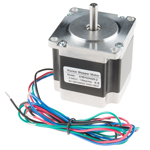 200 Steps Stepper Motor |
2 | Precise control for movement position |
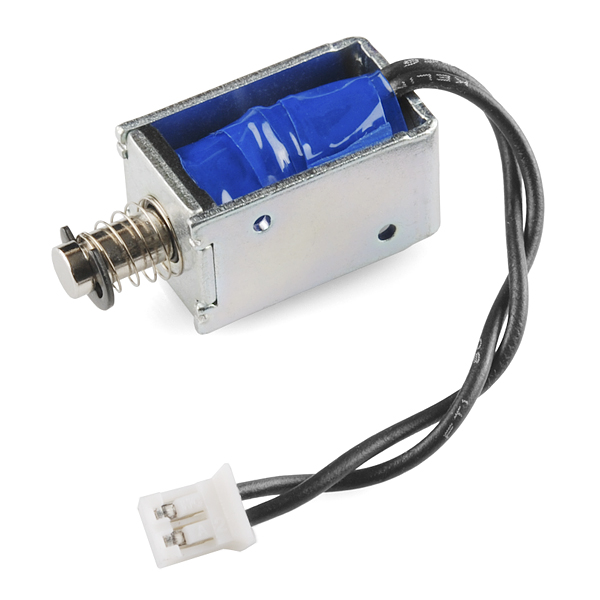 Solenoid |
1 | To activate the pen |
Structure
| Material | Amount | Note |
|---|---|---|
 Plywood Sheet |
4 | 4.5mm thickness |
 One Layer Cardboard |
7 | Used for prototyping; 3mm |
Components
| Material | Amount | Note |
|---|---|---|
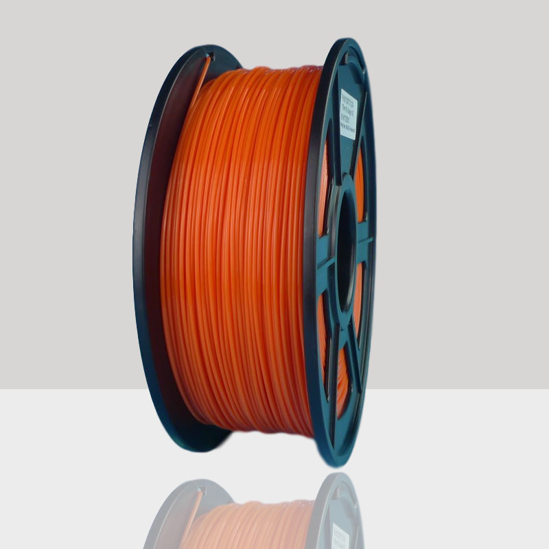 Filament of 3D printer |
roughly 200g from a roll | Shaft supports, pen holders, bearing holder |
 Pulley |
4 | / |
 Shaft Rod |
4 | / |
 Closed Round Rail Ball Bushing |
6 | / |
 Rubber Belt |
140cm+ | Have slightly more rubber rails to be divided between two rails |
 0.4mm Screws |
9 | For mounting components |
 0.2mm Screws |
8 | For mounting motor, solenoid |
Other
| Material | Amount | Note |
|---|---|---|
Map printouts |
3 | One for each route drawing |
Motor mount |
1 | Existing component from previous machine; can be cut using acrylic on laser cutter |