Final Project
OverView

About Project
The goal is to control the temperature of sake within the following range.
Range is 10℃ to 40℃
| Japanese | How to call | Temperature | Remarks |
|---|---|---|---|
| 雪冷え | Yuki Hie | 5℃ | Out of Range |
| 花冷え | Hana Hie | 10℃ | |
| 涼冷え | Suzu Hie | 15℃ | |
| 冷や | Hiya | 20℃ | |
| 人肌燗 | Hitohada Kan | 35℃ | |
| ぬる燗 | Nuru Kan | 40℃ | |
| 熱燗 | Atsu Kan | 50℃ | Out of Range |
Warm or cool using a peltier unit.
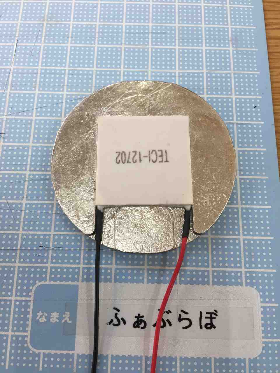
* About Peltier unit
- Using Peltierunit
- Size
- 30mm × 30mm × 4mm
- DataSheet
Create Process for Cup (Mold & Casting)
Design of a cup for Sake.
In order to make a tin cup, we first printed a 3D mold for making the mold.
The first
- 3D model Design data
Fill the 3D printed mold with gypsum clay and pour tin into the finished mold.
I thought that this would make a tin cup.
However, I did not cast well.
-
Mold created
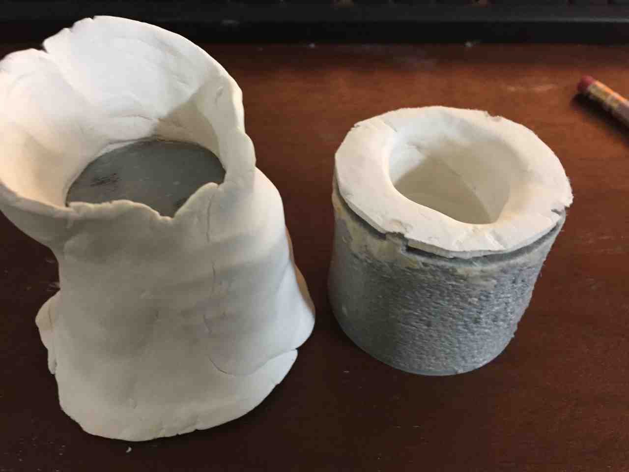

-
Finished casting

The thickness of the wall is not uniform, and a hole has been opened halfway.
I tried about 10 times and never succeeded.
The cause was considered as follows.
- If two templates are created from different templates, they will not be combined neatly.
- Gypsum clay contains water, so steam is generated.
Next time
So I changed the way to make the mold and the material.
The mold is taken from the desired cup itself.
- 3D model Design data
3D print And then rubbed out the candles to smooth the surface.
This has the following advantages over putty.
- It is cheap
- It becomes smooth when rubbed
- It melts when warmed when taking out
Mold after rubbing with candles

Pour mold and plaster into a cup of the right size.


There is no deviation of the mold because it makes male and female molds from one mold.
In addition, because the plaster for casting is used, the quality is stable.
Cast

Finish

There was no water leak and a usable cup was made.
Materials For Mold & Casting
| Qty | Description | Price | Link | Notes |
|---|---|---|---|---|
| 1Kg | Tin Ingot | 40.92 $ | Amazon | |
| 1Kg | Plaster | 7.90 $ | Amazon | |
| 1 | BabyPowder | 3.29 $ | Amazon | |
| 1 | Potash soap | 15.24 $ | Amazon | |
| 500g | Plasticine | 9.23 $ | Amazon |
Create Process for Case
Create a case for use in the final project.
Cooling and warming surfaces
Design the outer frame of the Peltier unit.
Cut MDF with laser and melt tin to make shape.
Used for casting because there is excess tin.
-
2D Design

-
cutting

-
combine

-
casting

-
FitIn

Cooling and warming surfaces Ver2
A new place for installing a temperature sensor was provided.


Case Design (Subtractive)
The following 3D model was created using Fusion360.
A developed view of the above model was created for laser processing.
The 3D model above was created with the assumption of using MDF 2.5 mm thick.
Therefore, I created data for laser processing.

- Laser cut case and insert tin plate.

Case Design Ver2
The first one I created was to use an OLED(SPI) because the interface was poor.
Change the position of the fan and install the OLED(SPI) instead.
The 3x2 pin header for writing the program could be diverted as it matched the pins needed for the OLED(SPI) display.

LED Light
Guide the LED light out of the case.
Cut the acrylic board to create a light path.

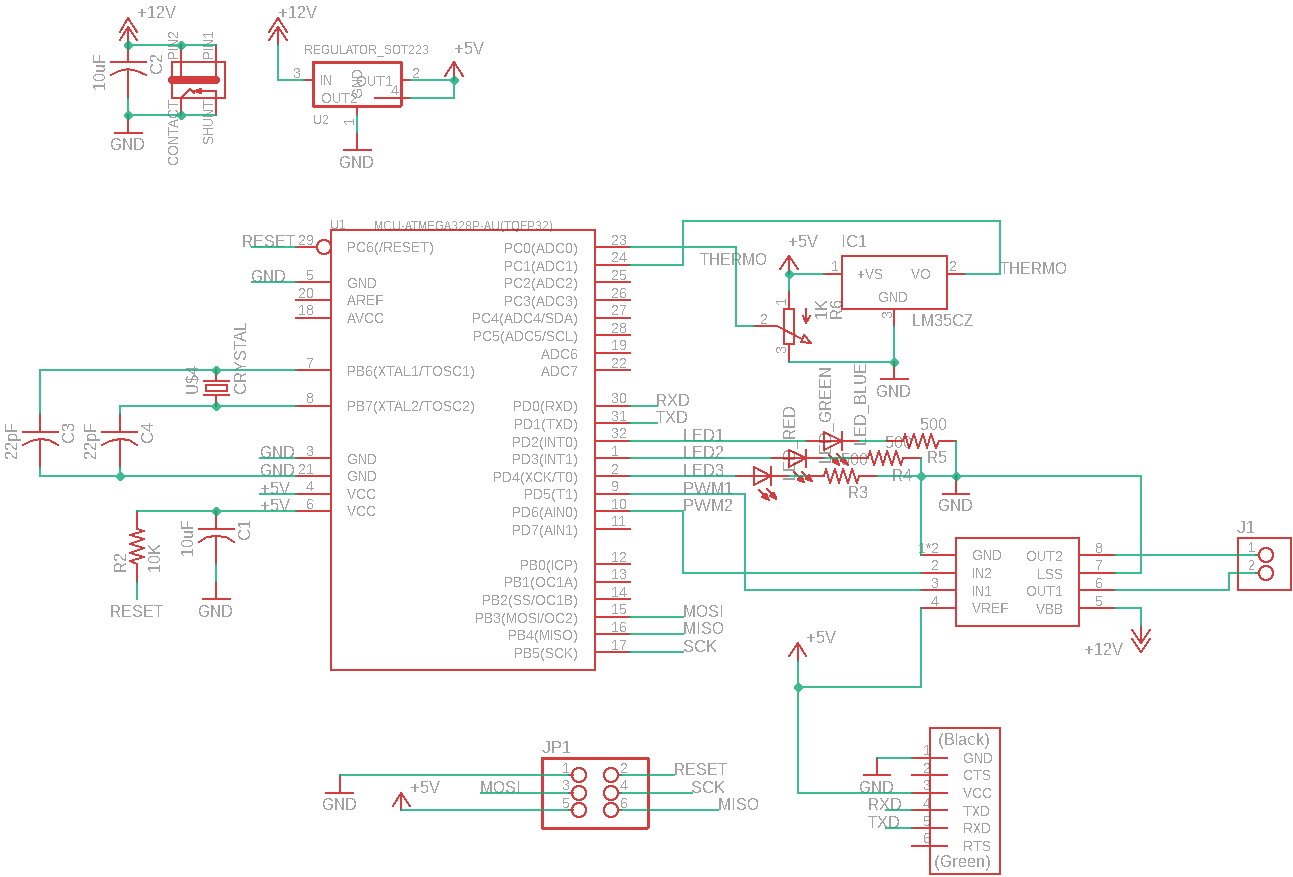
Electronics Design (Electronics)
Design a circuit to be incorporated in the created case.
The size of the circuit was restricted because the substrate was cut out in a form of press fitting to the case.
The components of the circuit are as follows.
- Main CPU
- Power supply
- 12V 3A
- Power is supplied to the CPU at 5v with the regulator.
- Potentiometer
- Used for temperature setting
- Temperature sensor (InputDevice)
- Used to measure temperature
- Peltier unit (OutPutDevice)
- Used to change the temperature
- PC fan
- Use for air cooling
- Program writing pin
- Pin for serial communication
- Three LEDs for setting
- OLED(SPI) for User Interface
- The pin for program writing can be used as it is.
- CLK = SCK
- MOSI = MOSI
- RES = RESET
- DC = MISO
- CS = GND
- VCC = VCC
- GND = GND
- The pin for program writing can be used as it is.

This circuit was cut out using MDX-15.


The back of the circuit is MDF, the jumper pin was soldered to the surface.

Noise removal (After Final Project Presentation)
There was a problem that the temperature sensor contained noise.
I talked to the experts and tried to remove the noise.

Noise was generated from the motor driver,
Therefore, the ground of the temperature sensor was wired directly to the ground of the power supply.

As a result, the noise disappeared.

By putting something that generates noise into a closed circuit loop,
the influence on other circuits can be reduced.
Materials For Circuit
| Qty | Description | Price | Link | Notes |
|---|---|---|---|---|
| 1 | Peltier Element 2A | 8.53 $ | Amazon | |
| 1 | PCFan | 6.00 $ | Amazon | |
| 1 | HeatSink | 4.00 $ | Amazon | |
| 1 | LM35DZ | 1.00 $ | Akizuki | |
| 1 | ATMEGA328P-AU-ND | 3.00 $ | Digi-Key | |
| 1 | MoterDriver(A4953) | 2.00 $ | Digi-Key | |
| 1 | ACAdapter | 17.09 $ | Amazon | 12V 3A |
| 1 | ACJack | 1.59 $ | Digi-Key | |
| 1 | Regulator(NCV1117) | 0.59 $ | Digi-Key | |
| 1 | Crystal | 0.73 $ | Digi-Key | 20Mhz |
| 1 | 3x2 PinHeader | 0.91 $ | Digi-Key | |
| 1 | Serial PinHeader | 0.28 $ | Digi-Key | 6pin |
| 1 | Potentiometer | 1.46 $ | Amazon | |
| 1 | Connecter | 4.02 $ | Amazon | 2.54mm pich |
| 1 | LED Red | 0.41 $ | Digi-Key | |
| 1 | LED Blue | 0.44 $ | Digi-Key | |
| 1 | LED Green | 0.38 $ | Digi-Key | |
| 1 | 1.3” OLED Display | 10.50 $ | Amazon | SPI : Driver SSH1106 |
Capacitors
| Qty | Description |
|---|---|
| 1 | 10 μF |
| 1 | 1 μF |
| 2 | 22 pF |
Resitors
| Qty | Description |
|---|---|
| 1 | 10 KΩ |
| 3 | 500 Ω |
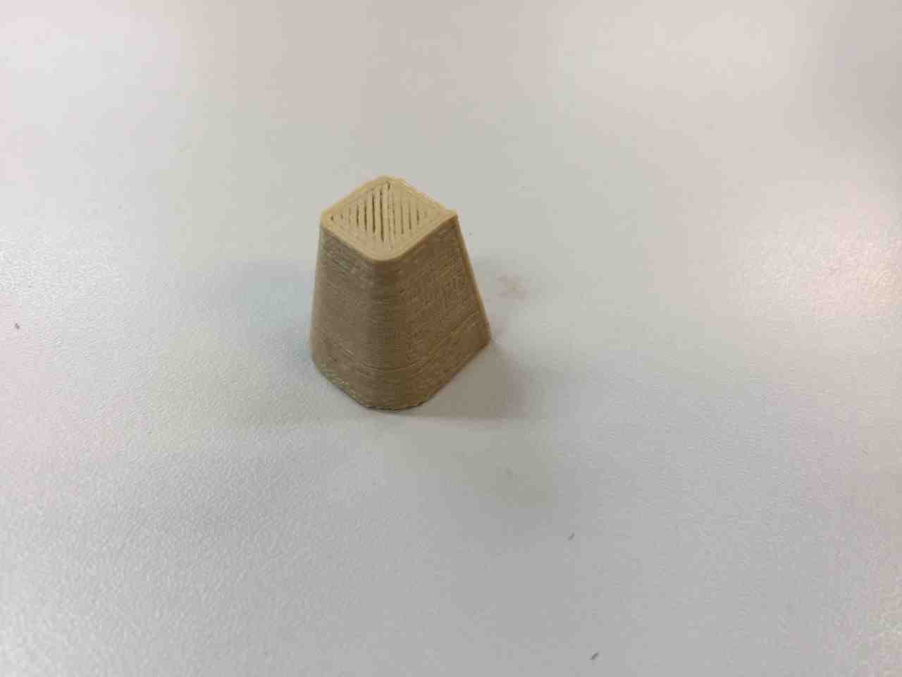
3D Print For Handle (Additive)
3D print the potentiometer handle.
Finished is here.

Project Image
The final project form was completed by combining those created.


Project Image Ver2


Programming
The programming used Arduino.
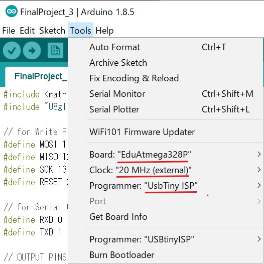
Since I used a 20Mhz crystal for the ATMEGA 328 operating clock,
I needed to prepare Arduino’s Hex file and board settings.
Hex file & board setting
I placed a hex file in the folder where I installed Arduino.
C:\Program Files (x86)\Arduino\hardware\arduino\avr\bootloaders
Also, added board settings using boards with hex files to boards.txt.
C:\Program Files (x86)\Arduino\hardware\arduino\avr\boards.txt
I wrote in Arduino as the following settings.
Program
The contents of the program used in the final project are as follows.
#include <math.h>
#include "U8glib.h"

// for Writing Programm
#define MOSI 11
#define MISO 12
#define SCK 13
#define RESET 22

// for Serial Communication
#define RXD 0
#define TXD 1

// OUTPUT PINS 5,6
#define PWM_PIN_1 5
#define PWM_PIN_2 6
// LED PINS 0~4
#define LED_1 2
#define LED_2 3
#define LED_3 4

// INPUT PINS
// TERMO_SENSOR PIN 15 A1
#define THERMO_SENSOR A1
// POTENTIOMETOR PIN 14 A0
#define TEMPERATURE_SETTING A0
//  PWM OUTPUT VALUE
#define PWM_VALUE 255

// Temperature Setting Value
#define COOL 1
#define NORMAL 2
#define WARM 3

// OLED SH1106 Driver setting
// SW SPI Com: SCK = 13, MOSI = 11, CS = 10, A0(MISO) = 12
U8GLIB_SH1106_128X64 u8g(13, 11, 10, 12);

float temperature = 0.0;
int setting = NORMAL;
String strSetting = "NORMAL";

// OLED Display draw
void draw(void) {
  // graphic commands to redraw the complete screen should be placed here
  u8g.setFont(u8g_font_unifont);
  //u8g.setFont(u8g_font_osb21);
  byte strLen = u8g.drawStr( 0, 22, "NowTemp:");
  u8g.setPrintPos(strLen + 5, 22);
  u8g.print(temperature);
  strLen = u8g.drawStr( 0, 44, "Setting:");
  u8g.setPrintPos(strLen + 5, 44);
  u8g.print(strSetting);
}

// initialize
void setup() {
  //  Serial.begin(9600); // for Debug
  analogReference(DEFAULT); // AnalogRead range of 0~5V
  pinMode(PWM_PIN_1, OUTPUT);
  pinMode(PWM_PIN_2, OUTPUT);
  pinMode(LED_1, OUTPUT);
  pinMode(LED_2, OUTPUT);
  pinMode(LED_3, OUTPUT);

  pinMode(THERMO_SENSOR, INPUT);
  pinMode(TEMPERATURE_SETTING, INPUT);

  resetLED();

  // flip screen, if required
//  u8g.setRot180();

  // set SPI backup if required
  //u8g.setHardwareBackup(u8g_backup_avr_spi);

  // assign default color value
  if ( u8g.getMode() == U8G_MODE_R3G3B2 ) {
    u8g.setColorIndex(255);     // white
  }
  else if ( u8g.getMode() == U8G_MODE_GRAY2BIT ) {
    u8g.setColorIndex(3);         // max intensity
  }
  else if ( u8g.getMode() == U8G_MODE_BW ) {
    u8g.setColorIndex(1);         // pixel on
  }
  else if ( u8g.getMode() == U8G_MODE_HICOLOR ) {
    u8g.setHiColorByRGB(255,255,255);
  }

  pinMode(8, OUTPUT);
}

void loop() {
  // GetTemperatureSetting
  setting = getTemperatureSetting();
  // GetTemperatureValue
  temperature = getTemperature();
  // Output PWM
  outputPWM();
  // 1000ms wait
  delay(1000);
  // picture loop
  u8g.firstPage();
  do {
    draw();
  } while( u8g.nextPage() );
}

/**
 * get Temperature
 * return setting
 */
int getTemperatureSetting(){
//  Serial.println("getTemperatureSetting Start");
  int ret = NORMAL;
  // analogRead 0~1023
  int val = analogRead(TEMPERATURE_SETTING);
  if(val < 350){
    digitalWrite(LED_1, LOW);
    digitalWrite(LED_2, LOW);
    digitalWrite(LED_3, HIGH);
    ret = WARM;
    strSetting = "WARM";
  }else if(val > 700){
    digitalWrite(LED_1, HIGH);
    digitalWrite(LED_2, LOW);
    digitalWrite(LED_3, LOW);
    ret = COOL;
    strSetting = "COOL";
  }else{
    digitalWrite(LED_1, LOW);
    digitalWrite(LED_2, HIGH);
    digitalWrite(LED_3, LOW);
    ret = NORMAL;
    strSetting = "NORMAL";
  }
//  Serial.println(ret);
//  Serial.println("getTemperatureSetting End");
  return ret;
}

/**
 * read Temperature Value
 * return temperature 0~50
 */
float getTemperature(){
  Serial.println("getTemperature Start");
  // Read analog Value
  int val = analogRead(THERMO_SENSOR);
  float temp = val * (506.0 / 1023.0);
  temp = floor(temp * 100) /100;
  Serial.println(temp);
  Serial.println("getTemperature End");
  return (float)temp;
}

/**
 * Turn off All LED
 */
void resetLED(){
  digitalWrite(LED_1, LOW);
  digitalWrite(LED_2, LOW);
  digitalWrite(LED_3, LOW);
}

/**
 * PWM OUTPUT
 * COOL = output PWM_PIN_1
 * WARM = output PWM_PIN_2
 * int tempSetting
 * int tempValue
 */
void outputPWM(){
  switch (setting){
    case COOL:
      // surface cooling
      analogWrite( PWM_PIN_1, PWM_VALUE);
      analogWrite( PWM_PIN_2, 0);
    break;
    case WARM:
      // surface warming
      analogWrite( PWM_PIN_1, 0);
      analogWrite( PWM_PIN_2, PWM_VALUE);
    break;
    case NORMAL:
    default:
      // don't output
      analogWrite( PWM_PIN_1, 0);
      analogWrite( PWM_PIN_2, 0);
  }
}
Result
Did the following
Change the temperature setting.
Display information on the OLED.
Change temperature
In order to make it easy to understand the change in temperature, a slime whose color changes with temperature was used.
It becomes pink when it gets warm and purple when it gets cold.

Indicate on the Display
Indicate setpoint and temperature with OLED.

Files
- TincupMold
- Tincup
- TinPlate
- TinPlateVer2
- Case
- CaseVer2
- Circuit
- CircuitCutPattern
- Handle
-
- Librariy imported when using the ATMEGA 328P with Eagle
- Hexfile for working Arduino 20Mhz
- Hex file for writing a program at 20Mhz with Arduino
- Arduino board settings for 20Mhz
- Board Setting for Arduino 20Mhz
Useful Links
- Nousaku
- Locally famous tinware company
- SnapEDA
- For Eagle Library Site
- 2018 Student edgareduardo Week18
- Successful students writing Arduino at 20mhz.
After FabAcademy
FabAcademy 2019 is finished, but I created a link for when I wanted to continue.
Fablabs.io