Input Devices
Group members
This week we were supposed to measure the analog levels and digital signals in an input device.
Work description
Measuring analog signals
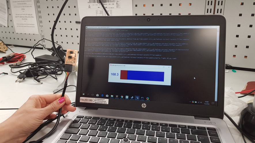
We connected Behnaz’s board to the computer to provide it power (5V), and ran the hello.light.45.py to see that the phototransistor was working.

We used oscilloscope to measure analog signal coming from a sensor, which was Behnaz’s phototransistor. We connected the alligator pin of the probe to the ground on the board, and then placed the other head of the probe to the input pin on the ATTiny. We saw the signal change, when we covered the phototransistor with our finger. See video below:
When not covering the phototransistor (in fluorescent lighting) the voltage value was 1, when covering it completely it was 5 – This value corresponds to the voltage provided by the computer through the FTDI cable.
Measuring digital signals
To measure the digital signals coming from the light sensor/microprosessor to the computer throught the Tx pin of the ftdi cable we again used the oscilloscope. We connected the alligator clip of the oscilloscope probe again to the ground, and the other pin to the tx pin. The amplitude of the signal was roughly 5 volts. The signal was roughly 5V.