03. Computer-controlled cutting
Group Assignement
- Characterize your lasercutter, making test part(s)
that vary cutting settings and dimensions.
Individual Assignement
- Cut something on the vinylcutter
- Design, lasercut, and document a parametric press-fit construction kit,
accounting for the lasercutter kerf,
which can be assembled in multiple ways.
Characterize your lasercutter
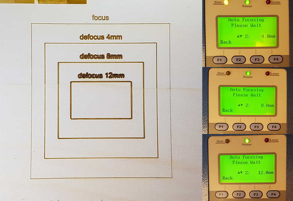
The Opendot's lasercut is a Spirit GLS. With my group provided to characterize the machine with a series of tests. After experienced with engraving and interference on playwood 4mm, as you can see on Laura Cipriani's page, we provided to test the machine on popler 3mm material, the one I chose for my press-fit kit. We can see that engraving is a technique very time expensive, that can be avoided in some specific but frequent case, using some trick. For my project I want to create a pattern decoration made by lines, so I can work in vector settings that are faster than raster ones. During the lecture on computer-controlled cutting by Neil Gershenfeld, was explained that in a lasercut, a laser ray is focused by lens in a specific point, where create a cutting with 0.2mm of width, more or less. But what happen if I defocused voluntarely? In this case the line is not more 0.2mm, but its width increases so as increases the defocus. So we prepared a test with 3 different steps of defocus, from one to other we move down the bed of lasercut for 4mm, to evaluate when the borders of lines becames unacceptable. When the laser is perfectly fosued (the machine have Autofocus), the width of line is 0.2mm. When we moved down the result was absolutly acceptable, the line's width is now 0.6mm. At 8mm was again perfectly acceptable, the lines have a good uniformity of width, that is now 1mm, just in corners there is a little smooth. At 12mm the line was again clean, the width is now 1,4mm but the smooth on corners was more evident, is perfect again for curviline drawing. This trick is very useful when we need to create solid texts or words and don't want spend so much time in engrave the solid hatch of letters o numbers (we have alwais remember that in this case we have use vectorline and font in single stroke fonts and we have disable raster)
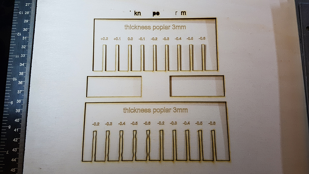
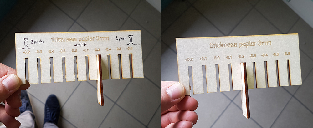
In the second test, we have provided to design two tests to verify the kerf and the interference for joint. This is suited for popler with 3mm thickness. The setting for this test are Speed 4% - Power 100% - 500 ppi for cutting, and Speed 70% - Power 100% - 500 ppi for engraving. The tests demonstrate that we have the best result in kerf, reducing of 0,2mm the ideal dimension of joint in cad drawings (0,1 for each side). The best interference to have a solid joint between two pieces in propler 3mm, is one pinch at the middle of join's side, with 0,15mm of width.
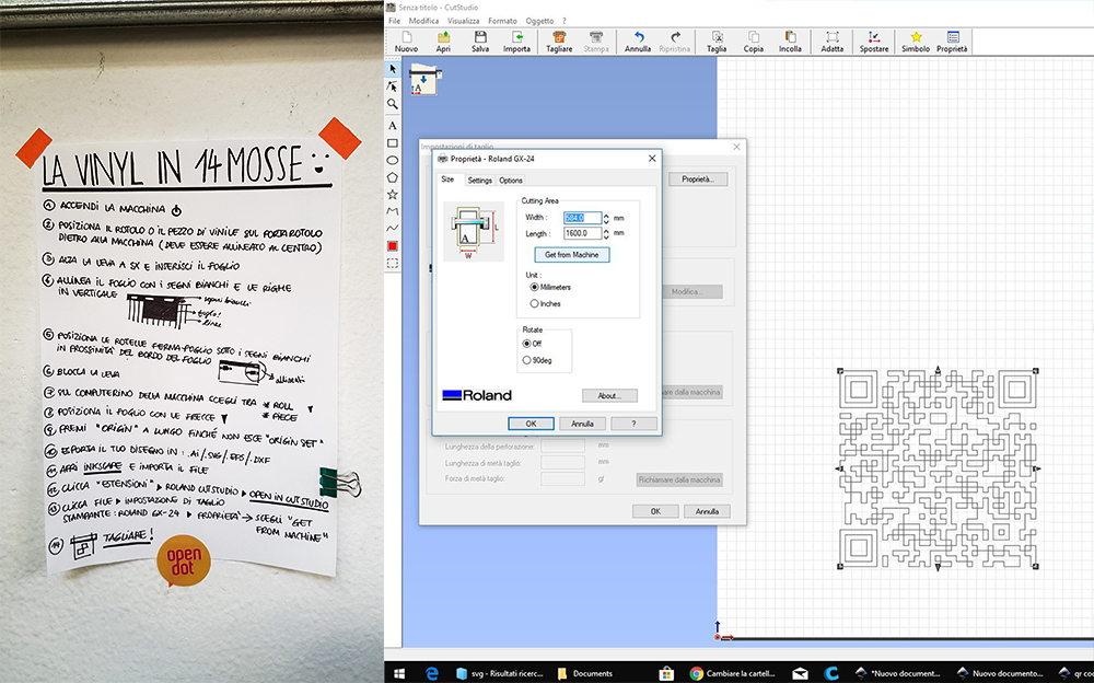
Cut something on the vinylcutter
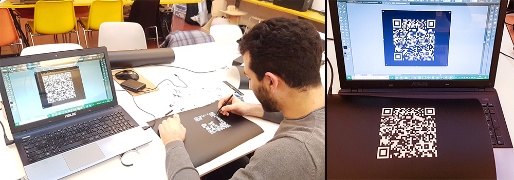
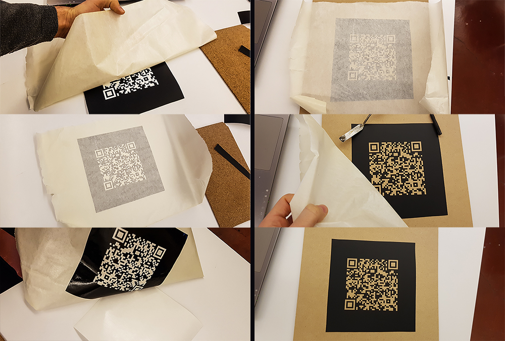
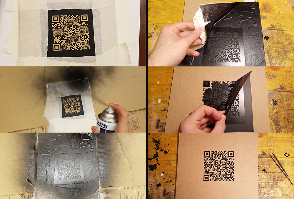
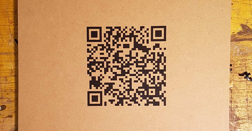
For first point of individual assignement I decided to create a Qr Code of my personal Fab Academy web site, and cut it on the vinylcutter. I think to put my Qr Code on my lamp base by engraving, but for now, I want try to cut a vinyl one and use it as stencil mask on a piece of MDF. For do this I've genereted a static Qr code on "qrcode.littleidiot", and saved it in "eps" file. Then I've opened the Qr Code in Illustrator, just for ensure that the vectorial lines was very perpendicular and cleaned.
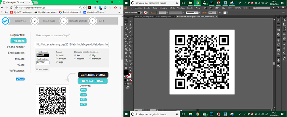
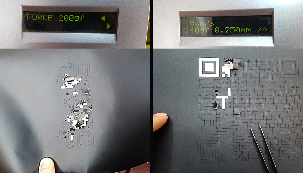
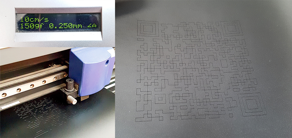
Near vinylcutter in Opendot fab lab, there is a manual for use the vinylcutter in 14 steps on the wall, written by tutors. The machine is a Roland Camm-1 Servo. I've follwed the instruction list, so I moved on pc connected to vinylcutter and opened the Qr code eps file in Inkscape, and from here I've exported directly in vinylcutter software: "Cutstudio". I've put the black vinyl roll in the machine and I've clicked on "Get width from machine" to set automatically the cutting area width.
Design, lasercut, and document a parametric press-fit construction kit
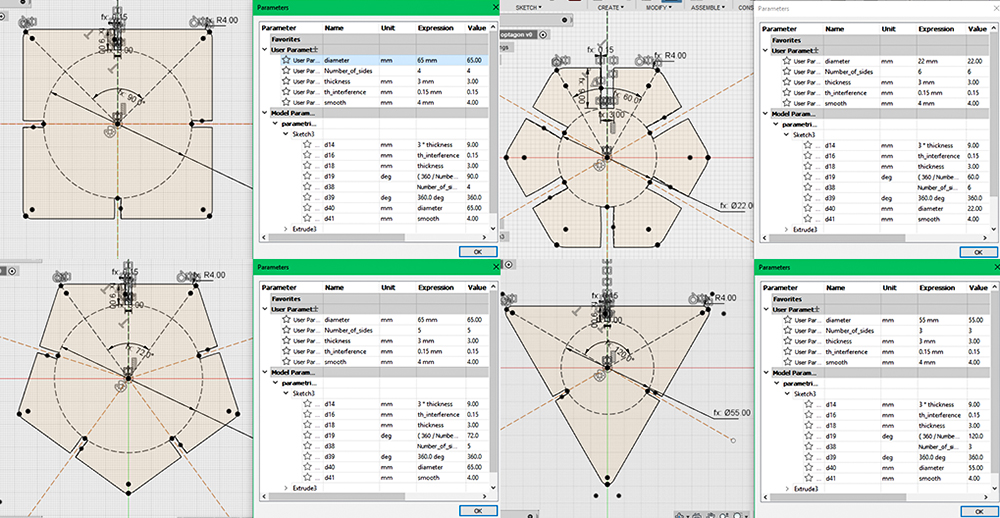
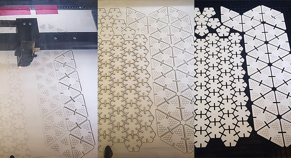
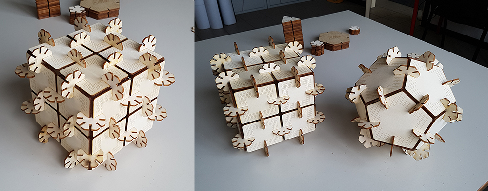
My press-fit project concern in a series of regular polygons, with a join on each side, that can be assembled each other in a million of possile solution. Fantasy is the only limit. In this case, modeling in parametric software is an amazing solution, because I could parametrize every characteristic of my polygons and change the shape just changing the parameters, without remodeling the enteire object any time. One of this parameter could be the number of sides, so was sufficient to model one polygon and obtaining all others just changing 2 parameters: the scale of polygon (changing the diameter of the inscript circumference) and the number of sides. I've worked in Fusion 360 by Autodesk that is a parametric software, free if you are a student, educator or hobbist. For the project I'll use popler sheet, the same that I've tested during group assignment on the characterization of lasercutter. I started designing the join, that must be the same for every polygon. I've designed it giving a numeric parameter to the width: 3mm, the same of popler sheet's thickness. I've given an unit-less parameter to the height of join, it must always be 4 times the thickness. I've given an interference of 0,15mm, that i found be good during characterization of lasercut. I've given a smooth to the two ends of lines, with a radius of 4mm, fixed for all polygons. I've costrained all the sketch to an angle, and dimensioned with the equation: 360°/Number of sides, so that changing the number of sides, the sketch recreate a regular polygon with the exact number of sides I want. After that i've circumscraibed the sketch starting from the origin of polygon, constraining it to the vertex of sketch. In this way I simply can change the size of polygon changing the diameter of circumference that is another parameter.
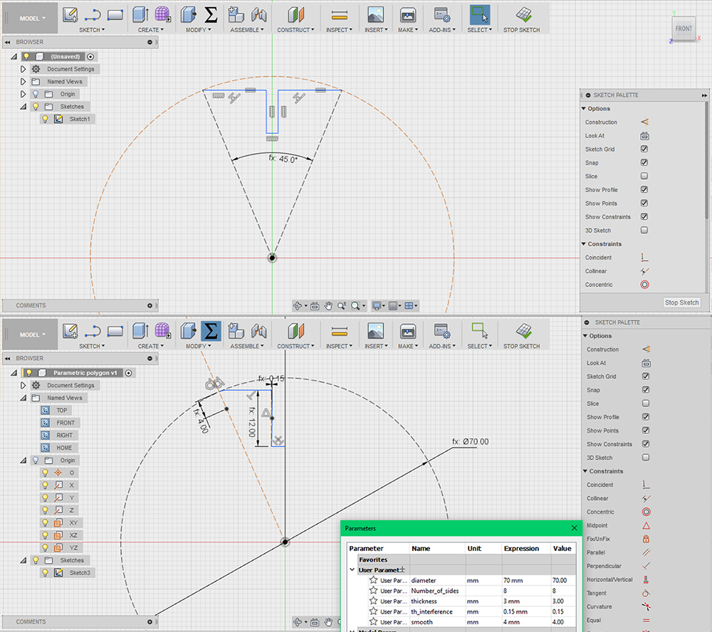
I've applied a circular pattern to my sketch, having as center the origin of circumference. Now is possible to me changing the number and the size polygon, just changing diameter of circumference and number of sides. I started with 8 sides for an optagon. In the end I've extruded the sketch putting as distance the parameter "thickness" (3mm, the deep of popler sheet). To export in DXF, the format file supported by lasercuts, I've installed in Fusion an incredible plug-in: DXF for Laser. This automatically calculates the offset in according to kerf value found in the tests of characterization, 0.1mm was the best value.
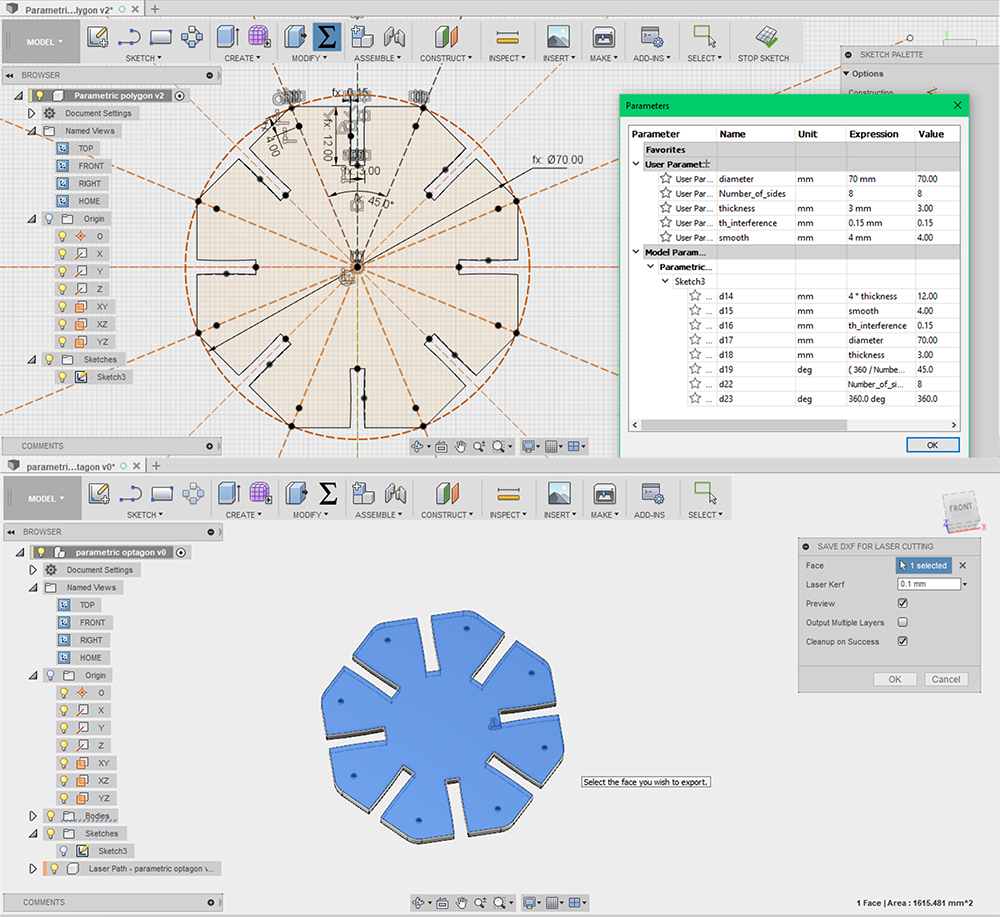
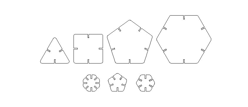
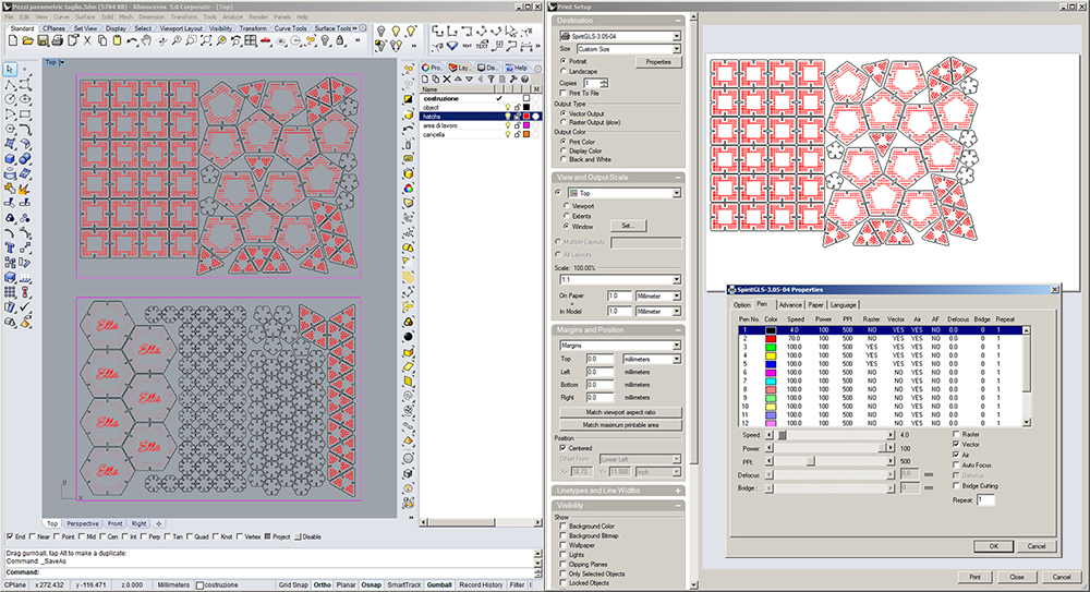
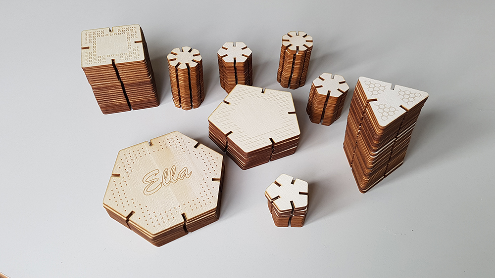
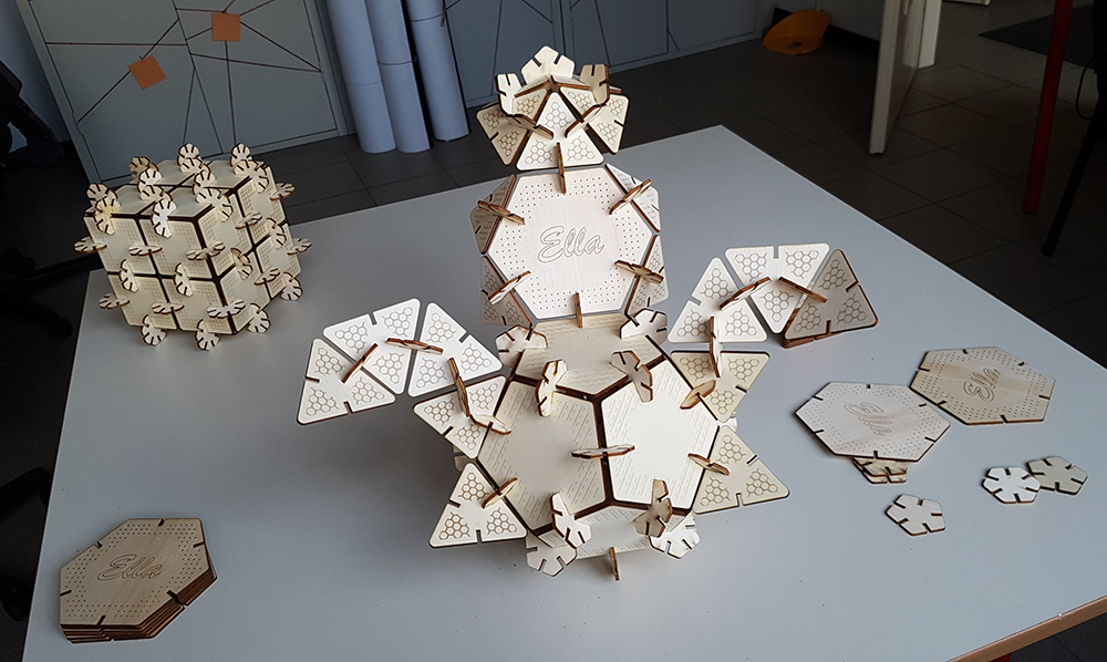
I've opened the DXF files in Rhinoceros 3D, drew some decoration using hatchs, and made a nesting on an area 700cm x 500cm, the dimensions of popler sheets. I've chosed to design triangles, squares pentagons and hexagons, that have same side. Then I've designed smaller octagons, pentagons and hexagons that are my joint elements, so I can assembly and play with a large series of angles: 45°, 60°, 72° and their multiples. I've put drawings to engrave on a red layer and cut ones on a black. For cut I put 4% of speed and 100% of power, while 70% of speed and 100% of power for engraving. My decoration consists in texture lines, so I can work faster as vector, avoiding raster.
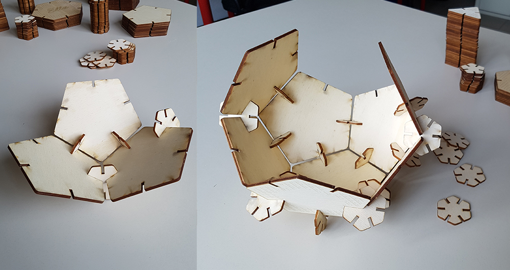
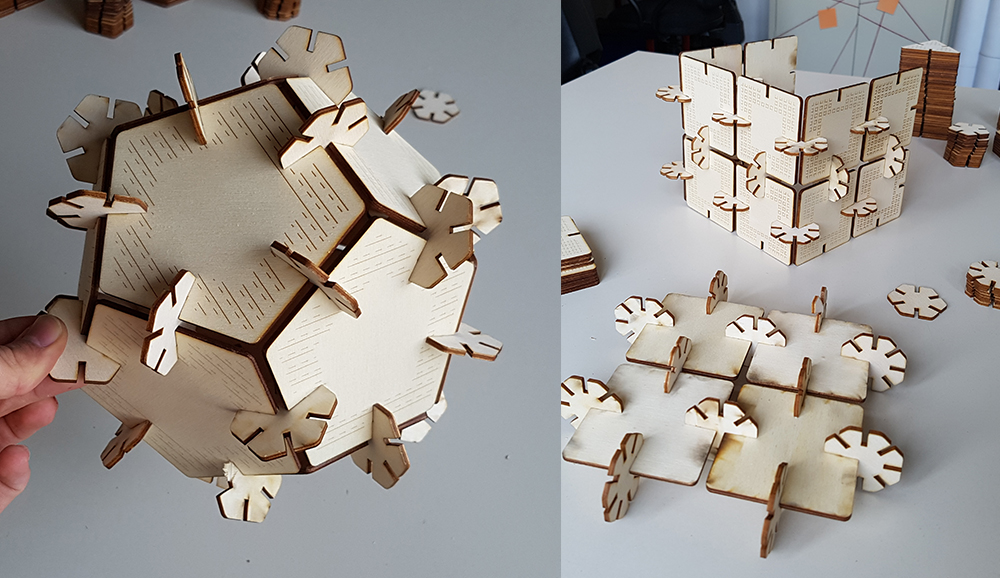
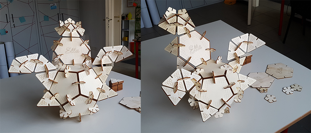
Finally I can play with my press-fit kit. The geometries I've chosen allow to create infinity possible combinations and forms. I can combinate in regular solid, as cube or dodecahedron, or more complex shapes. Having the same side for each polygon was a seccessful trick, because in the assembling, the transition from one polygon to another, between two neighboring sides, is continuous, because the sides are equal, and the shapes that can be created are perfectly consistent even when using different polygons.
Download
You can download test files here:
You can download Press-Fit kit files here: