Exercise 07: Electronics Design
Individual assignement:
Redraw the echo hello-world board, add (at least) a button and LED (with current-limiting resistor), check the design rules, make it, test it.
Learning outcomes:
Select and use software for circuit board design
Demonstrate workflows used in circuit board design
Have you:
Shown your process using words/images/screenshots
Explained problems and how you fixed them, including how you worked with design rules for milling (DRC in EagleCad and KiCad)
Included original design files (Eagle, KiCad, Inkscape, .cad - whatever)
Redraw the echo hello-world board, add (at least) a button and LED (with current-limiting resistor) check the design rules, make it, and test it
Here the steps:
- Presentation of the echo hello-world board o hello.ftdi.44
- Redrawing of the echo hello-world board with Eagle
- Export of the file in PNG format
- Milling the PCB
- Assembling the PCB
- Check my Work
- Software Installation
- Get and Build the Firmware
- Program the ATtiny44
- Test the programmer
Presentation of the echo hello-world board
I clicked on the echo hello-world board link to understand the shape, the components, the traces and outline. Then I followed the Fab Academy tutorial WEEK 6: ELECTRONICS DESIGN for the description of the hello.ftdi.44.Redrawing of the echo hello-world board with Eagle
I redrew the echo hello-world board, adding a button, a pull-up resistor, and a red LED with a resistor. For the drawing, I downloaded the software Autodesk Eagle. I followed the presentation of Tiziano Berti, Lab coordinator, with Enrico Bassi, our instructor and director at Opendot. It was all new for me. So I thanked them for the presentation and to have registered it. I also started to follow the WEEK 6: ELECTRONICS DESIGN Fab Academy tutorial: Introduction to Eagle, which I found very useful. I greatly thank Anna Kaziunas France and Eduardo Chamorro for the work done. I understand that I am very slow, and I need to be more disciplined and organized, but strangely, the course costed me so much in money and effort, that I think I'll overcome any obstacle.
I proceeded following the tutorial, opening a new project, Helloworld,

installing the fab.lbr library of components,

and created this schematic file: the drawing representing a circuit with the electronic components I downloaded from the libraries.
Here the components of my Helloworld board, later registered as Hello board:
Source: Fab Academy tutorial: Introduction to Eagle
- 6-pin programming header for programming the board.
- microcontroller attiny44A. It will be programmed and will remember the program.
- FTDI header. It powers the board and allows board to talk to computer.
- 20MHz resonator external clock;
- Capacitor. It stores energy in an electric field and can control voltage spikes.
- Resistor (value 10k ohms). Purpose: pull-up resistor. What is a pull-up resistor?
- Button
- Resistor (value 10k ohms)
- Ground
- VCC
- Red LED (Light Emitting Diode) - LEDs have polarity - the side with the line is the cathode and connects to the ground side.
- Resistor (value 499 ohms)
I added and moved the components in the schematic, following the instructions from the tutorial and using the commands Add, Move. Then I used the command Net for connecting pin 6 (PA7) on the micro-controller to the button; pin 10 (PA 3) to the LED.
So did I with parts of the 6-pin programming header, the FTDI header, the 20 MHz resonator, grounds and VCC (connections to power) as it is shown on the schematic. Here in the picture:
Another picture to connect two related pins while renaming them with a single name:

I checked the schematic for any errors, with the command ERC: electronic rules check, to ensure my board will actually work. I found no error and five warnings which were not important for the creation of my board. I was happy of the result:

I clicked in file to the function Switch to board and worked on the board file.
After a long time and many problems with the traces, I draw this board:

I clicked on Tools and on the command DRC: design rules check to fixe the clearance at 0.41mm for wire and pad in the Eagle design rules:

Then, I checked the board for any errors, to ensure my board will actually work. I found no error and two airwires on the button which were not important for the creation of my board:

I was happy of the result. I am thankful to Enrico Bassi for the optimization of the space on my board. He insisted on it. It took me a long time to move the objects, but I am proud of the result.
Export of the file in PNG format
I kept only the top and dimension as visible layers. I am thankful to my colleague Francesco Pasolino for reminding me to export it in monocrome. Then, I use the Inkscape software to design the outline. I wanted the shape of o flower which became a kind of star. Here the pictures of my trial:
 |
 |
|---|
Milling the PCB
Following the procedures I described in Exercise05, I converted the .png above pictures in .rml files for the Roland MD 40 milling machine. In my new job as a welder I had to mill more boards, so I post here two Flower board trace .rml files: one with a 0,4mm pcb cutter and a 0,3mm engraving bit. |
 |
 |
|---|
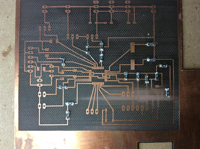
Then I milled the board as in the following pictures:
 |
 |
|---|
Here the result:

Assembling the PCB
It has been a long and hard adventure. In Exercise05, I used the soldering paste with stencils which was quite an easy procedure for a first experience. In this exercise, our instructor adviced us to use the soldering iron which requested me practice, method, and precision. I had a lot of difficulties and a long training. For soldering the components I followed the board design, and soldered in the easiest way for my dexterity.Here some pictures:
 > > |
 |
|---|
Check my Work
I checked my work with the digital multimeter, and apparently all the connections were responding well. I felt ready for programming my board.Software Installation
I followed the instructions as described in the Fab Academy WEEK 8: EMBEDDED PROGRAMMING>