TODO LIST
- Design and produce something with a digital fabrication process
Introduction
This week assignment is to make something new. I know, every week we do new things, But in this week i can do anything. The only pre requestment is Design and produce something with a digital fabrication process (incorporating computer-aided design and manufacturing) not covered in another assignment, documenting the requirements that your assignment meets, and including everything necessary to reproduce it. So i decided to make a E-textile. My plan is glow few LEDs that placed around the neck of a Tshirt . I decided to make a flexible PCB that can atach to any tshirt. Through this way, i can use them in any tshirt and also i can remove them while washing the Tshirt.
E-Textiles
LEDs and fiber optics as part of fashion
Electronic textiles, also known as smart garments, smart clothing, smart textiles, or smart fabrics, are fabrics that enable digital components such as a battery and a light (including small computers), and electronics to be embedded in them. Smart textiles are fabrics that have been developed with new technologies that provide added value to the wearer. Pailes-Friedman of the Pratt Institute states that "what makes smart fabrics revolutionary is that they have the ability to do many things that traditional fabrics cannot, including communicate, transform, conduct energy and even grow. Learn more
Schematics and PCB design.
First i need to design the schematics. I started designing the schematics using Eagle PCB. I used a Attiny44 Microcontroller. I have enough pins to conect all my LEDs and the sensor. I used a 3x3 LED charlie plexing to save microcontroller pins and to program them easly. I removed the ISP programing head because i just program them once. so i decided to remove them to avoide complexity in routing. I placed a 2x2 pin header to power the board externaly from a battery.
Making the Flexible PCB
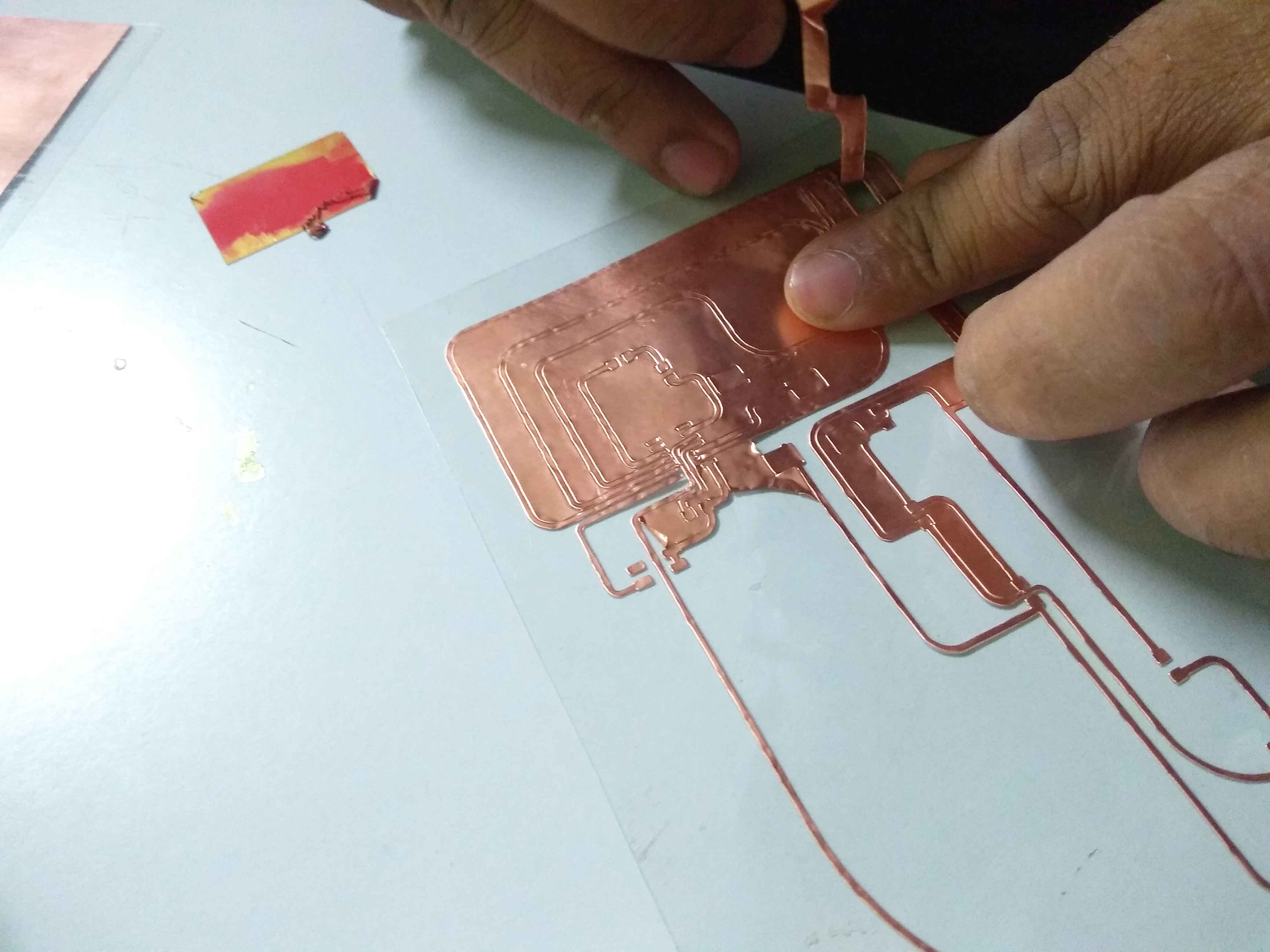
Now i need to make the flexible PCB. I decided to build one in my own way. To make a flexingle PCB, I decided to choose chemical eching using Ferric Chloride(FeCl3). I choose a OHP sheet as the base material for the PCB. Above of the vynyl sheet i stacked a copper tap sheet.
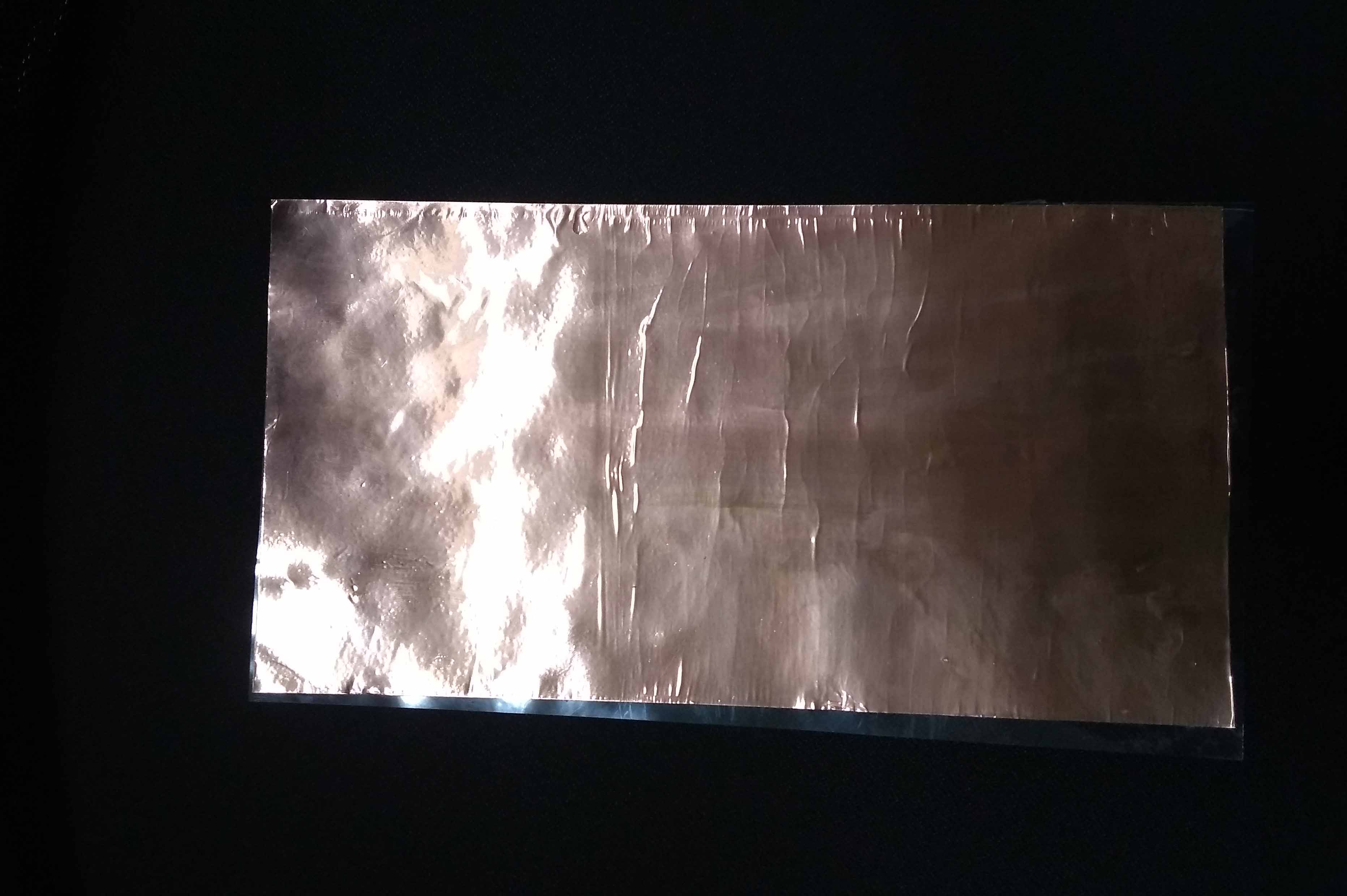
I removed the small bubbles traped inside the copper tap while placing the sheets together using a credit card.
Now the PCB board is ready but i need to make the design on the PCB. There are many ways to do that. I always choose milling the PCB using a PCB milling machine. I can also use vinyl cutter. So idecided to do in vinyl cutter machine.
Cut out PCB design using Vinyl cutter
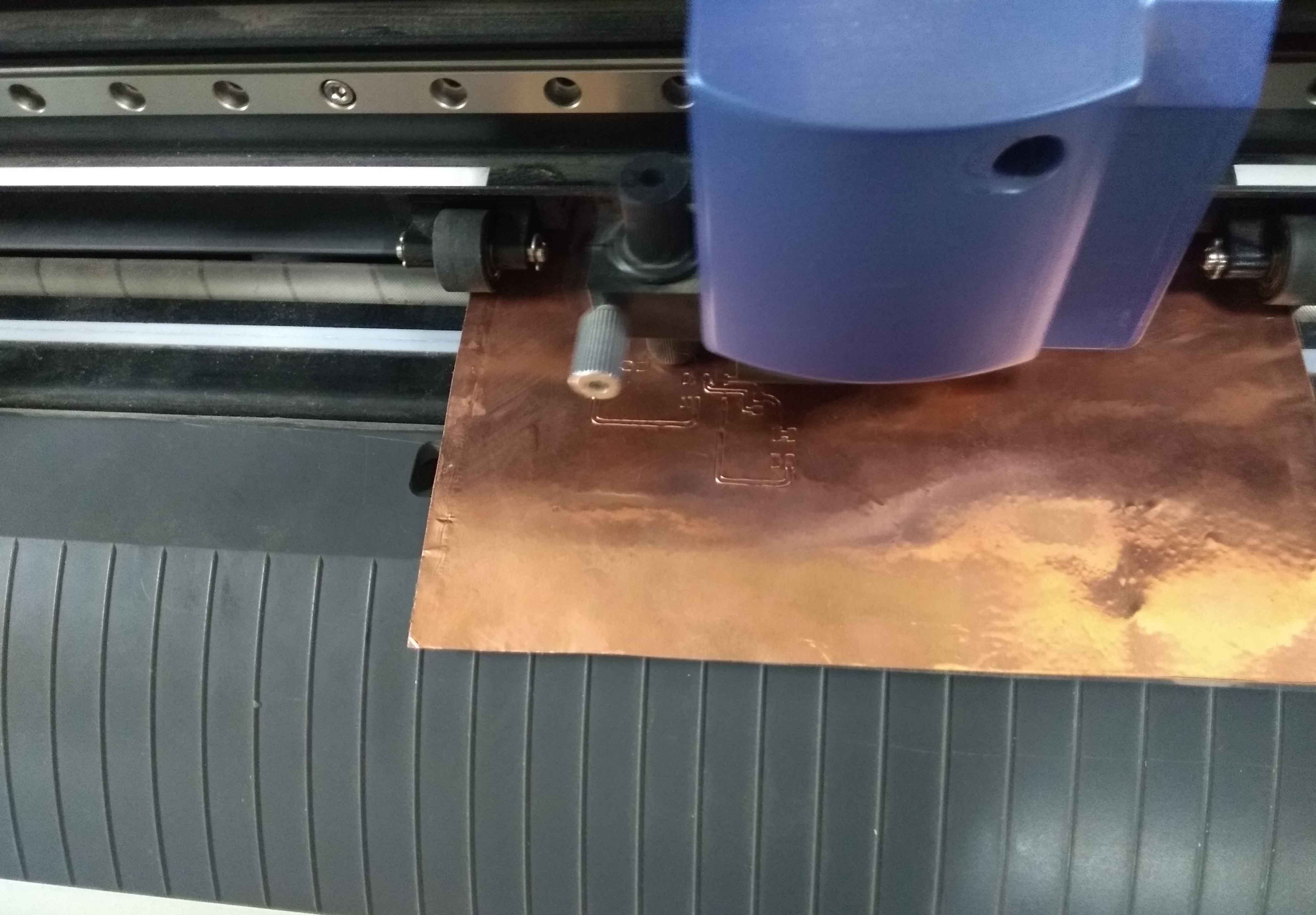
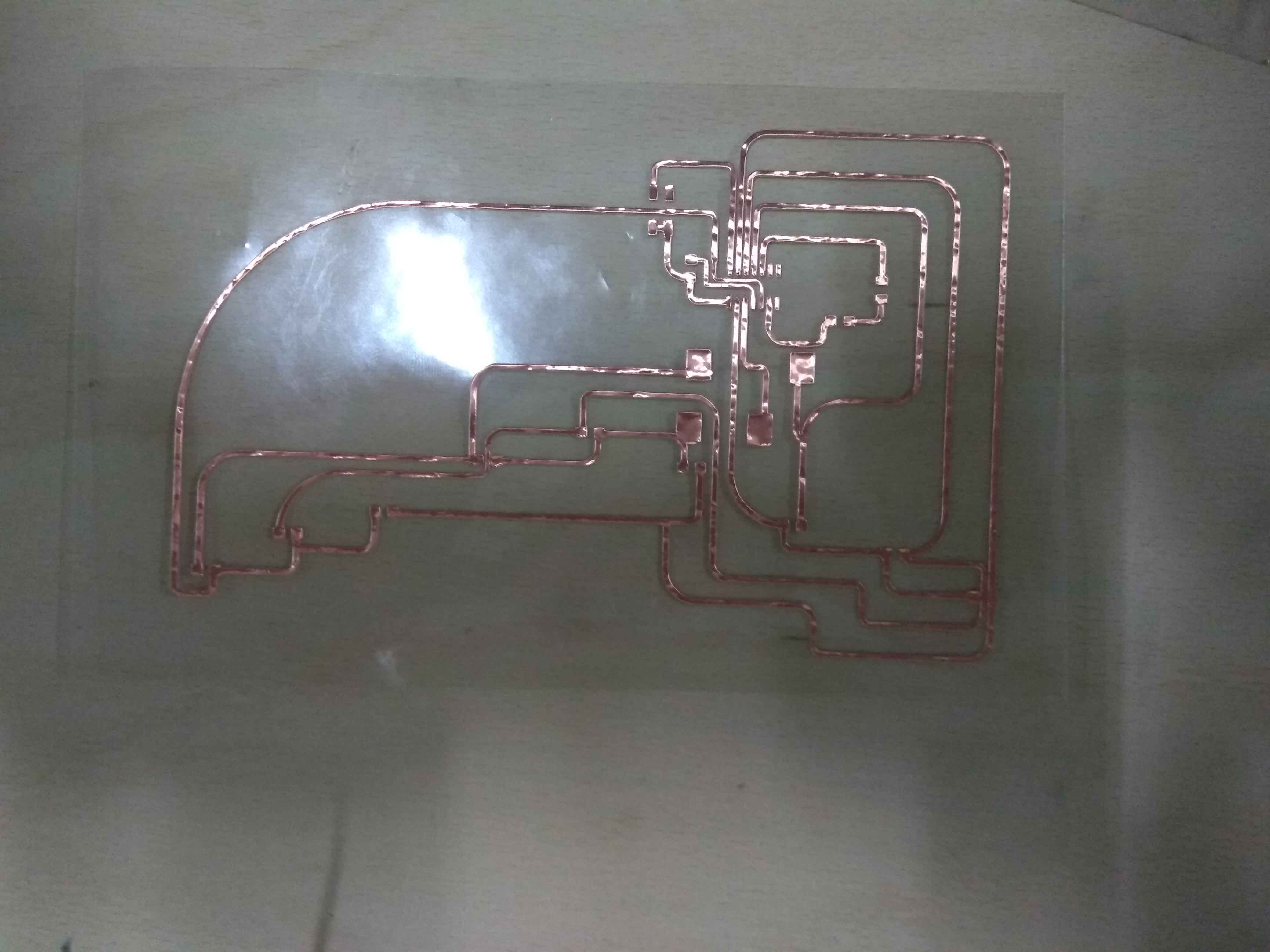
I placed the PCB sheet that i previously made in the vinyl cutter. After that opened the Fab modules and selected Roland vinyl cutter as machine. I loaded the png image file of my PCB design. I Selected Copper sheet as the material. i adjusted the force to 0. The machine started cutout the PCB.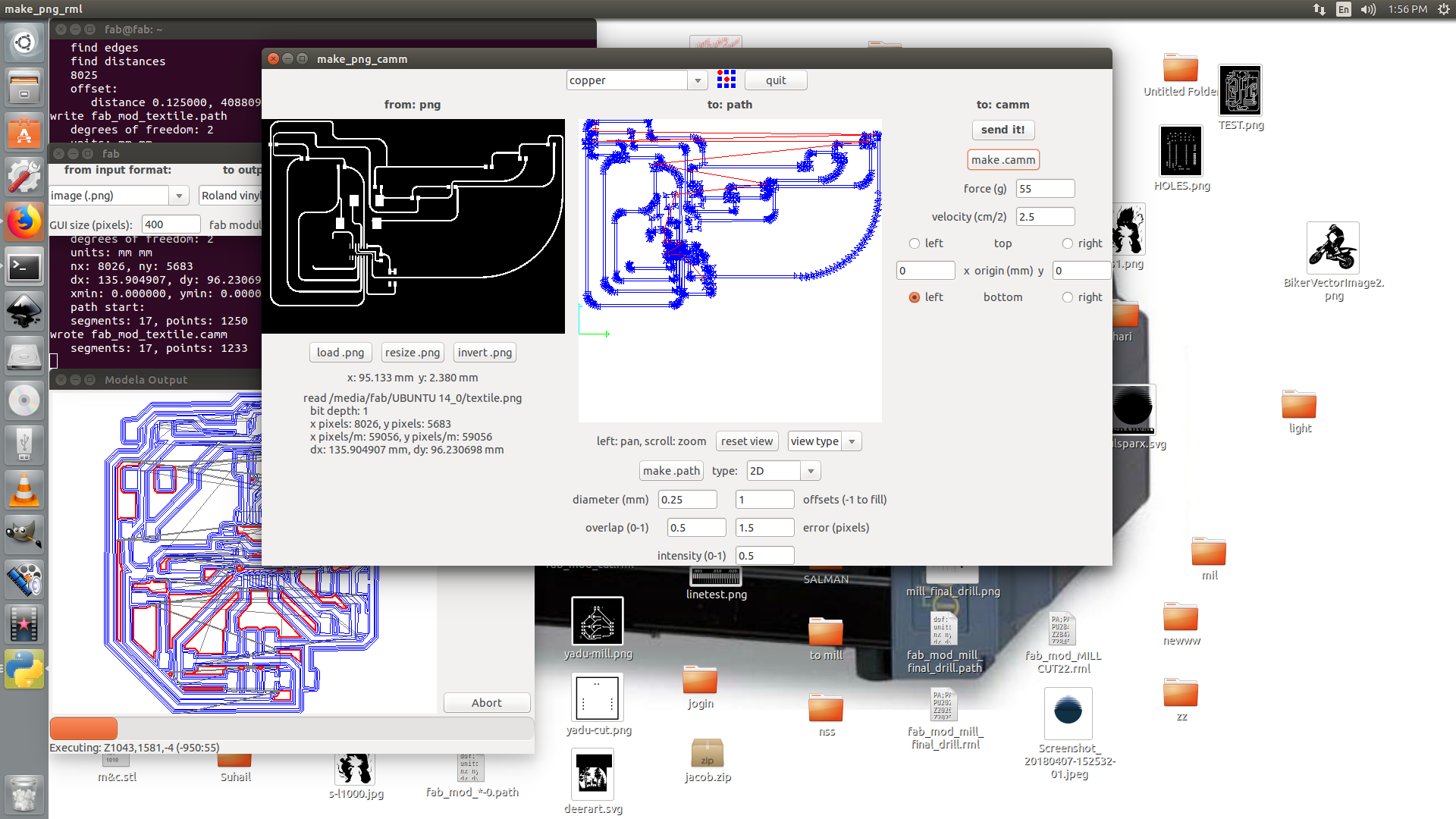
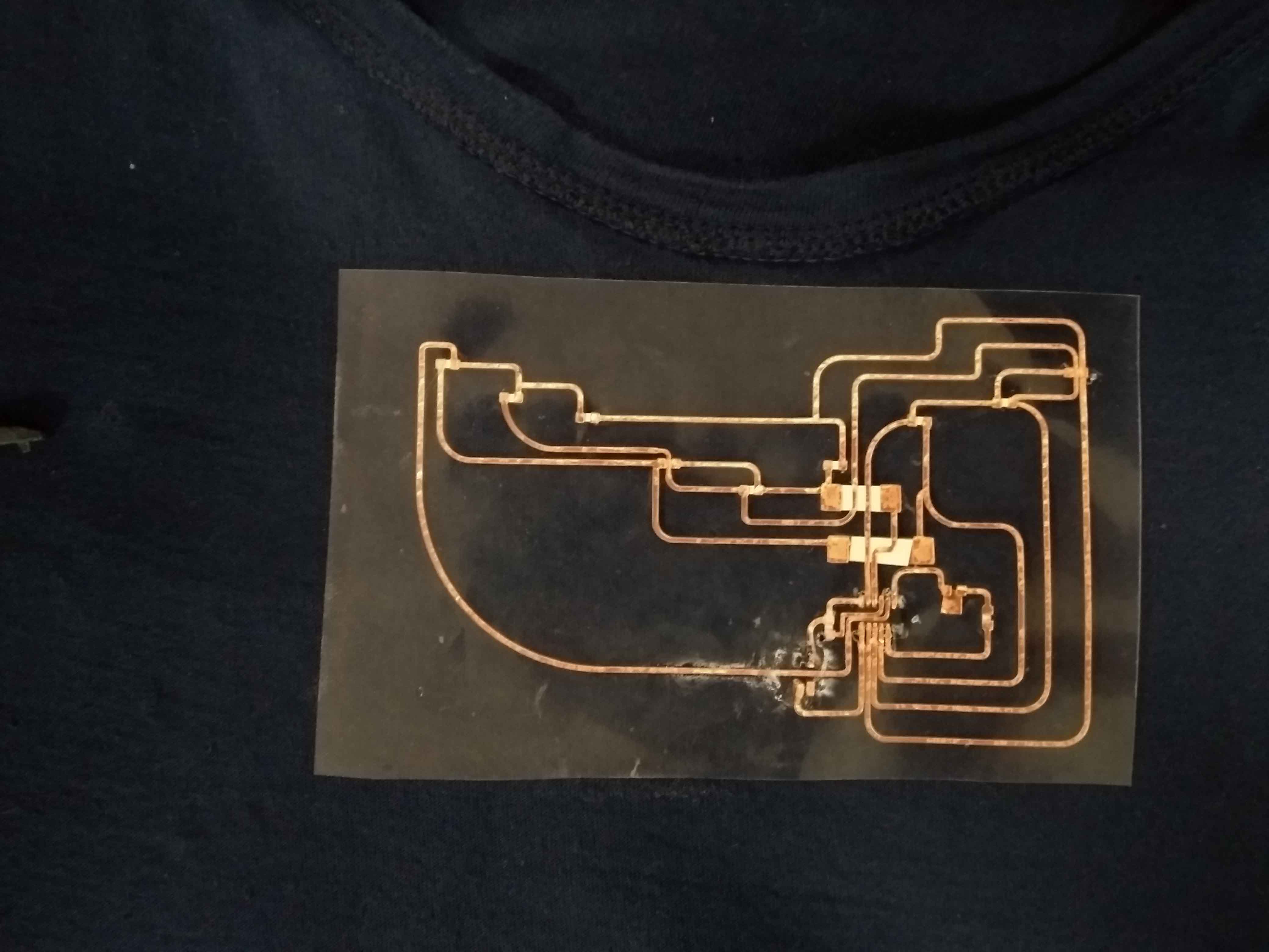
After cutting out the PCB. I carefully removed the unwanted copper tapes from the sheet. There is high chance to rip the traces too, so i used a tweezer to remove the copper.
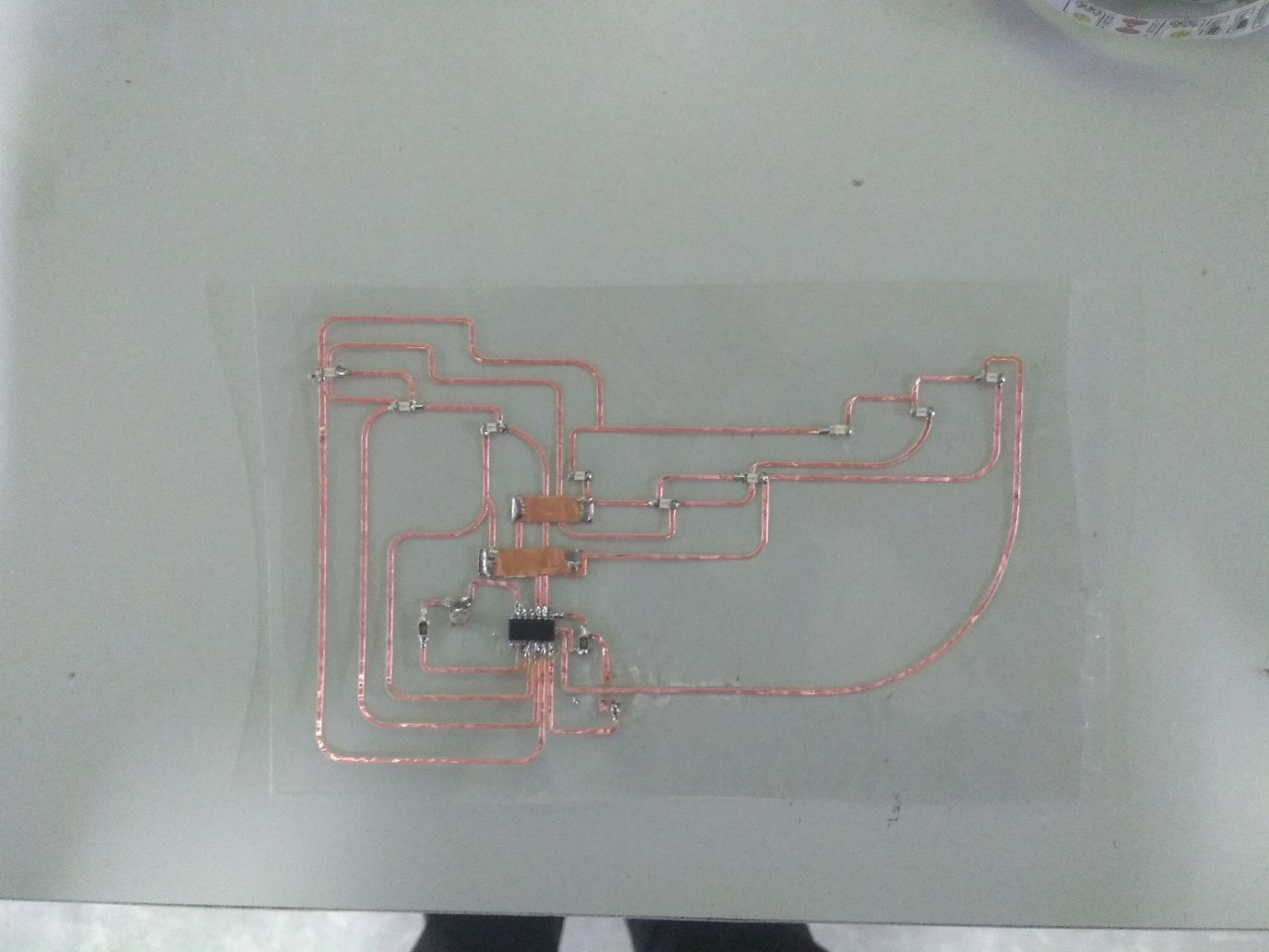
Soldering components
Now i need to solder all the components to the PCB. But it is not a easy task as it like we solder on a copper clad PCB. The OHP paper is not a heat resistive material. So there is high chance to melt down the sheet while soldering. So i need to solder components as fast as i can. I did the soldering pretty well. soldering the Attiny44 is little risky but i managed it.
Programming the board
Now i need to program the board to blink the LEDs. I wrote the code in arduino IDE. I does not gave a AVRISP pin header in my board because i just need only to program once and It is too difficult to route the traces. How ever i uploaded the code into the Attiny44 by directly taking wires from the programming pins (MISO,MOSI,SCK,RST,VCC,GND). If you dont know how to program Attiny microcontrollers using arduino please reffer my Embedded programming week
Arduino Code:
#define A1 10
#define A2 9
#define A3 8

#define C1 0
#define C2 1
#define C3 2

void setup() {
 pinMode(A1,OUTPUT);
 pinMode(A2,OUTPUT);
 pinMode(A3,OUTPUT);

 pinMode(C1,OUTPUT);
 pinMode(C2,OUTPUT);
 pinMode(C3,OUTPUT);

 digitalWrite(A1,LOW);
 digitalWrite(A2,LOW);
 digitalWrite(A3,LOW);

 digitalWrite(C1,LOW);
 digitalWrite(C2,LOW);
 digitalWrite(C3,LOW);

}

void loop() {
digitalWrite(A1,HIGH);
digitalWrite(C1,LOW);
digitalWrite(A3,HIGH);
digitalWrite(C3,LOW);

delay(80);
digitalWrite(A1,HIGH);
digitalWrite(C2,LOW);
digitalWrite(A3,HIGH);
digitalWrite(C2,LOW);

delay(80);
digitalWrite(A1,HIGH);
digitalWrite(C3,LOW);
digitalWrite(A3,HIGH);
digitalWrite(C1,LOW);

delay(80);
digitalWrite(A2,HIGH);
digitalWrite(C1,LOW);
digitalWrite(A2,HIGH);
digitalWrite(C3,LOW);

delay(80);

digitalWrite(A2,HIGH);
digitalWrite(C3,LOW);


int lDelay=random(80,2000);
delay(lDelay);
//////////////////////////////////
digitalWrite(A1,LOW);
digitalWrite(C1,LOW);
digitalWrite(A3,LOW);
digitalWrite(C3,LOW);

delay(80);
digitalWrite(A1,LOW);
digitalWrite(C2,LOW);
digitalWrite(A3,LOW);
digitalWrite(C2,LOW);

delay(80);
digitalWrite(A1,LOW);
digitalWrite(C3,LOW);
digitalWrite(A3,LOW);
digitalWrite(C1,LOW);

delay(80);
digitalWrite(A2,LOW);
digitalWrite(C1,LOW);
digitalWrite(A2,LOW);
digitalWrite(C3,LOW);

delay(80);

digitalWrite(A2,LOW);
digitalWrite(C3,LOW);

int rDelay=random(80,2000);
delay(rDelay);

}
Stiching the PCB to the T-Shirt
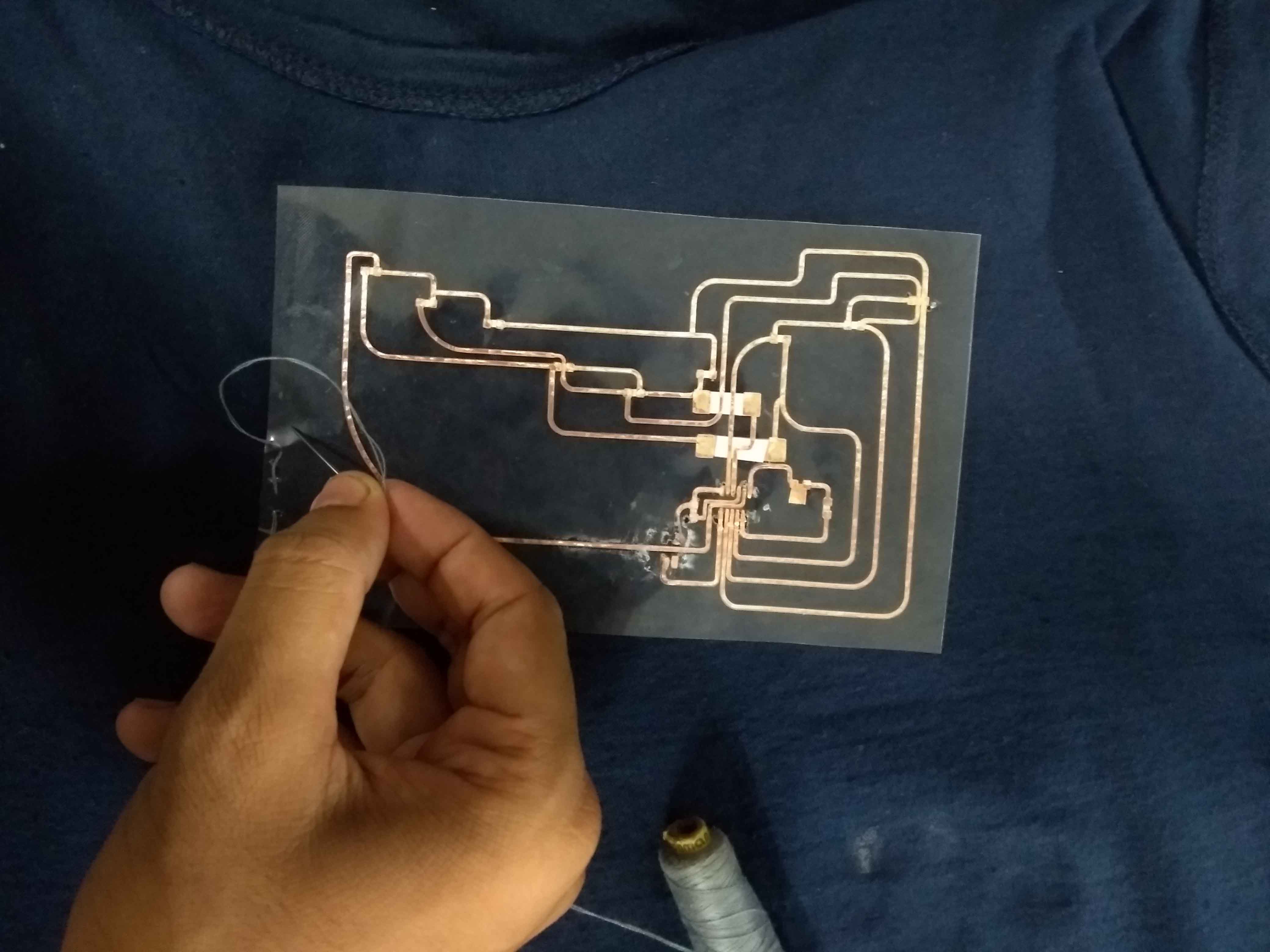
Now its time to stiching the PCB in to the Tshirt. I selected a T-shirt that i have already left for this project. Then i used a fine stiching needle and thread to stich the PCB into the T-Shirt.
I stiched the PCB from inside of the Tshirt. So it should noted by others and also the Tshirt will act as kind of diffuser for the LEDs.
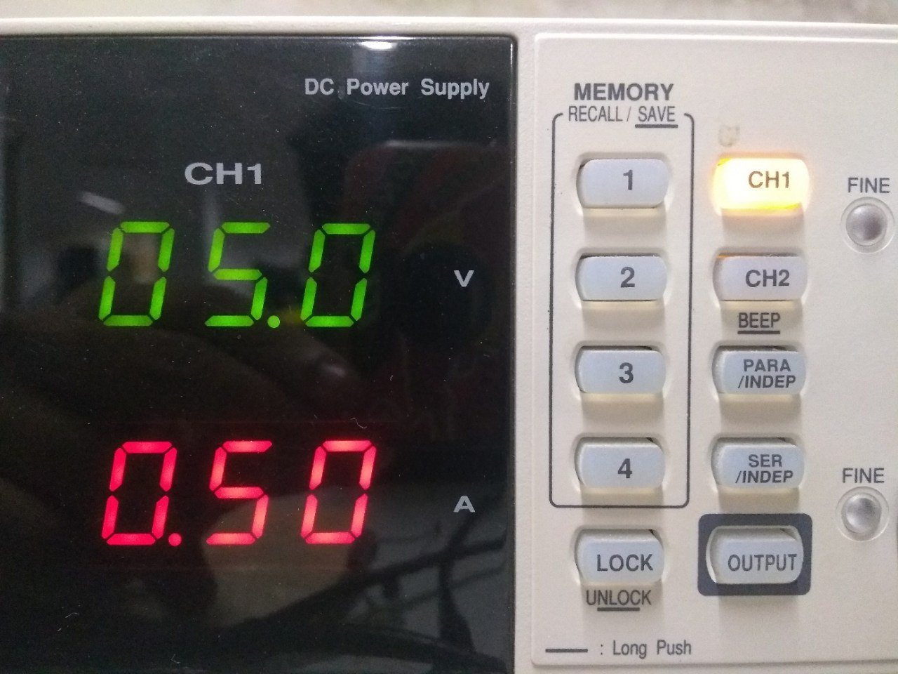
After stching all side of the PCB to the Tshirt. Its time to test my first E-Tshirt. After wearing the Shirt. I powered the Circuit using 5volt power supply that i took from Bench power supply. Now lets test it.
E-Tshirt Demo