Week 7. electronics design
Assignment
- group project: use the test equipment in your lab to observe the operation of a microcontroller circuit board
- individual project: redraw the echo hello-world board, add (at least) a button and LED (with current-limiting resistor) check the design rules, make it, and test it
group assignment
see FabLab Kamakura's group assignment page.
redraw the echo hello-world board (and add a LED and a button)
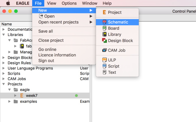
I'd already installed EAGLE. Before I started to redraw a board, I imported a library and a created new project, named it week7.

In the project, I created a new schematic, in which I'm going to place electronic components.
From "add" command, I searched for a component I needed in fab.lbr library.
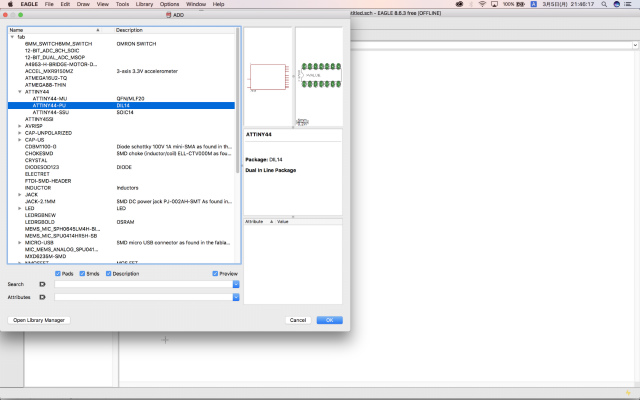
Then, I dragged and placed it on a schematic. ATtiny44, for example.

I put "label" and "name" on an each pin. Pins with the same name will be connected to each other later.
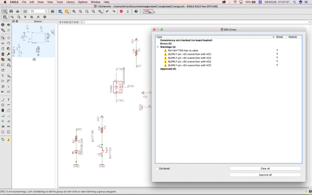
After I put all components on a schematic, I checked electric rule check(ERC).

If there aren't any dangling pins, which has no pin with the same name, I can go to next step. If any, I have to check the circuit design thoroughly.
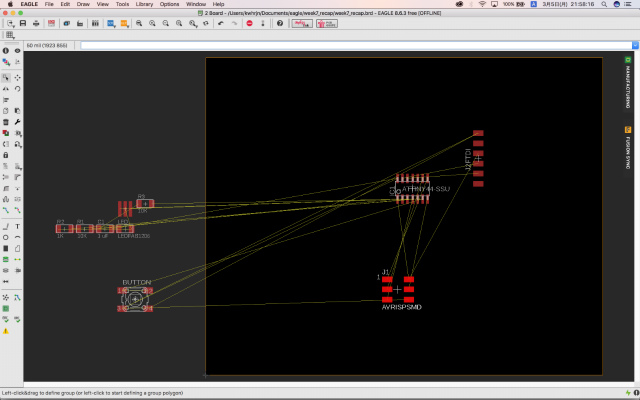
Then I generate/switch to board.

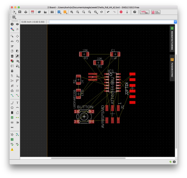
Yellow lines are so-called air wires, which are drawn in the shortest way to connect between components. I have to route them not to cross. A black pane of the right side in the window is the maximum size of the PCB I can use free version EAGLE. I don't have to worry about it in this case.

I dragged components to the pane, arrange the position of them.
I put them with reference to Neil's example and added a LED with a resistor and a tactile button on a blank space of the left side.
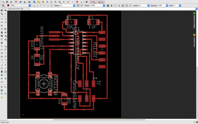
I drew lines between components with reference to yellow air wires. I shrunk the board outline. To put it mildly, I hated this routing process.

I shrunk the board outline.
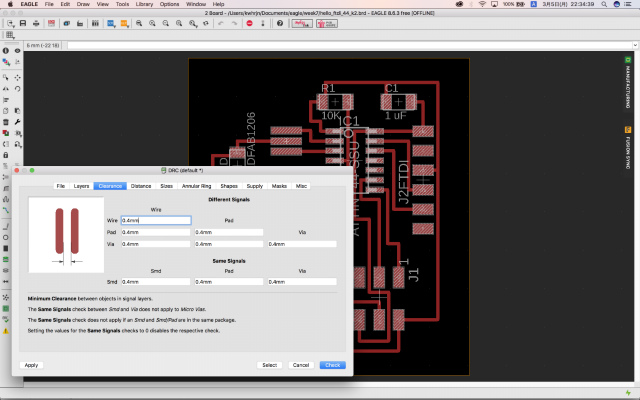
check the design rules and make it
I did the design rule check(DRC) with a wire width of 0.4 mm. To my relief, there were no errors.
I need .png image to make CAM(mods) generate g-code(rml) data.
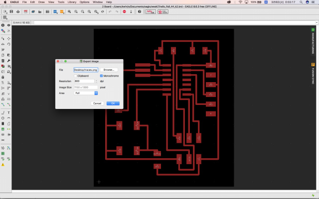
Here is how to export .png image from EAGLE. From Layer Settings, I selected only "Top(#1)" layer. It will be traces for milling.
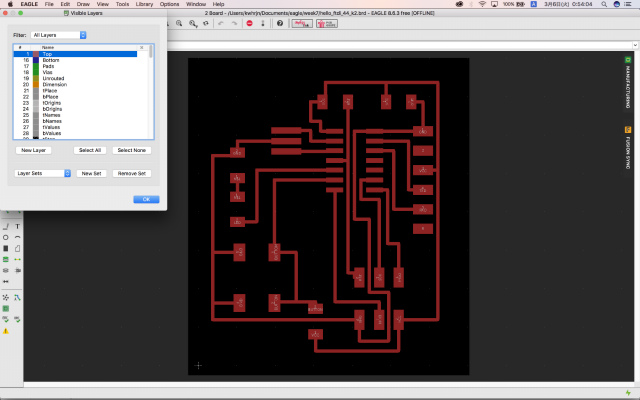
File->Export->Image

I chose .png (choose from Browse menu) format as an export image, checked Monochrome checkbox. Resolution setting was 800 dpi. Then, press OK button.
I have to do the same for an interior. The difference was to select layer #48 (Document).

EAGLE export error
Exported .png file dimension is 36.5 x 41.3 mm. I created .rml file for SRM-20 from mods and milled the board.

I stopped milling because the machining size was bigger than I expected. I checked the size in mods and found out that its size was doubled compared to the original board size. Three out of four lab members had the same export glitch of EAGLE.
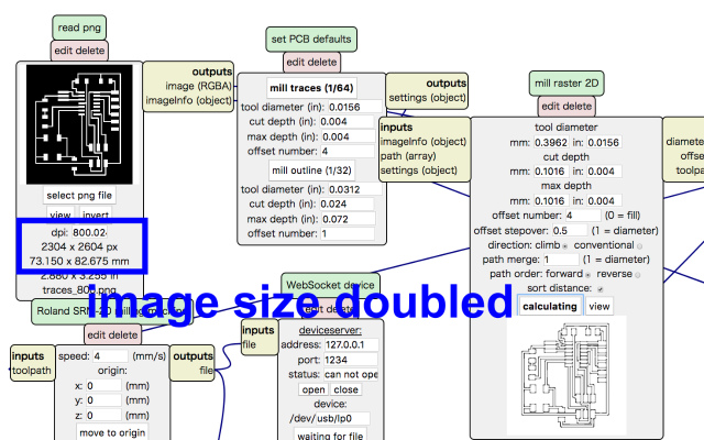
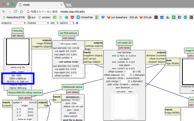
We managed to generate a proper size of .png file by modifying the setting of resolution. I enlarged 800 dpi to 1600 dpi by using preview application in Mac. Now mods recognized png file as actual size.

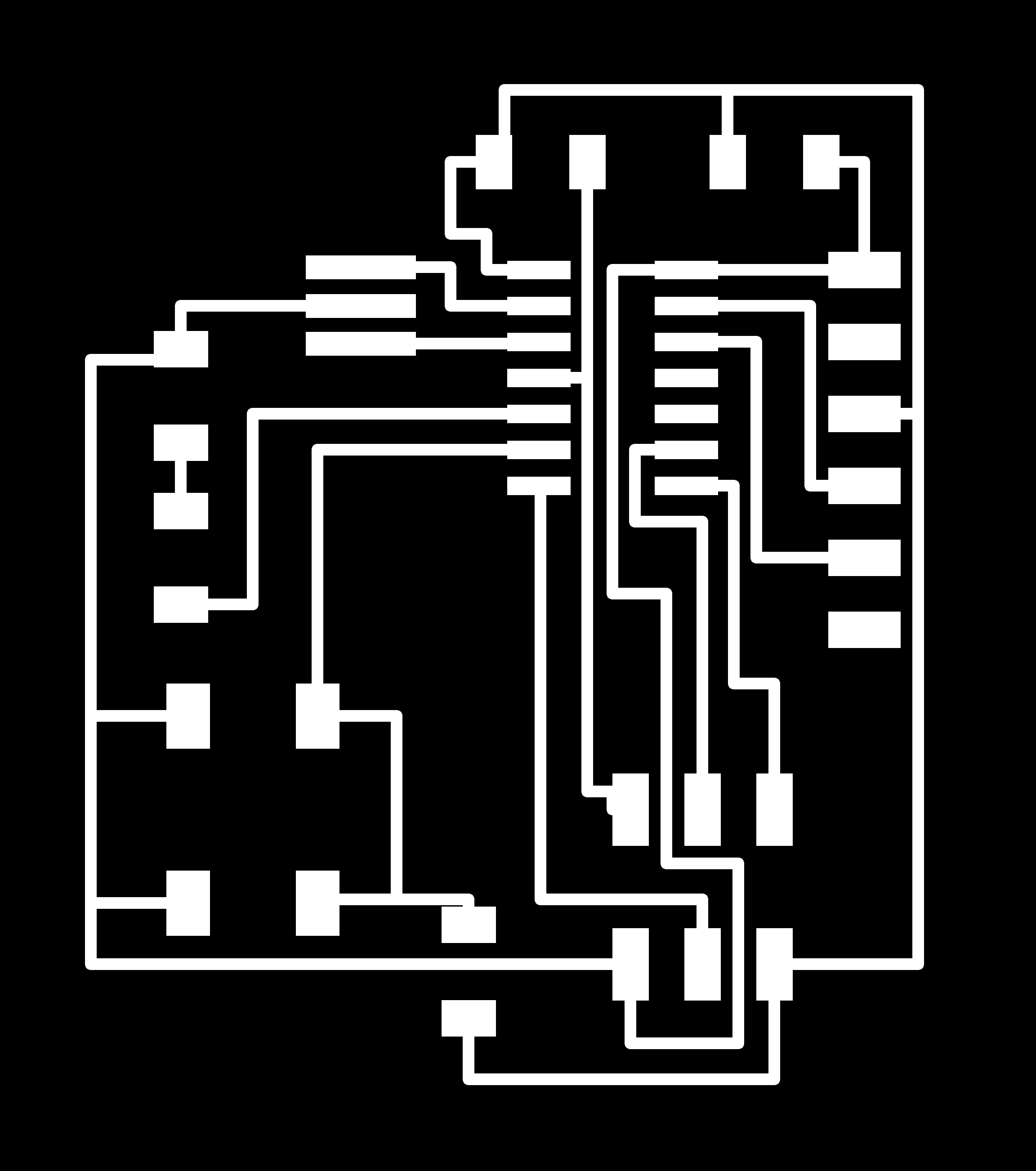
Here is the traces toolpath of my board.

I did the same with the interior toolpath.
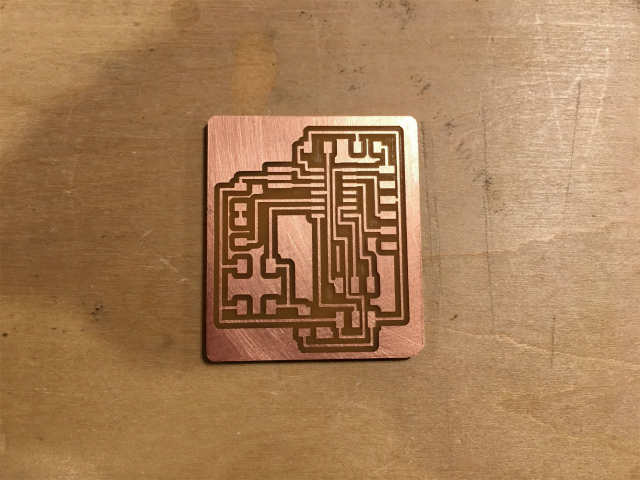
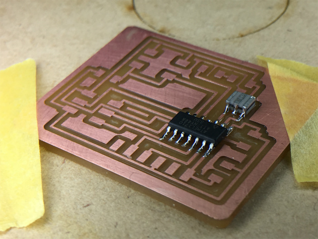
I machined traces with 1/64 drill mill bit and an interior with 1/32 as I did in week5/electronics production.
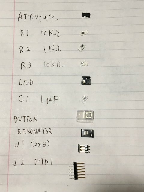
I picked out all components before soldering.
I carefully soldered an ATtiny44 and a resonator first and others.
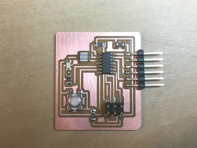
Finally, soldering done.
test it
Before I check my board, I installed pyserial with which python can use serial communication.
KWHRJN:Desktop kwhrjn$ sudo python get-pip.py
KWHRJN:Desktop kwhrjn$ sudo pip install pyserial
I followed this procedures to test my board. I used AVRSIP MkII to write a program to ATtiny and FTDI USB to UART converter cable.
"make" was fine.
KWHRJN:Desktop kwhrjn$ make -f hello.ftdi.44.echo.c.make
avr-gcc -mmcu=attiny44 -Wall -Os -DF_CPU=20000000 -I./ -o hello.ftdi.44.echo.out hello.ftdi.44.echo.c
avr-objcopy -O ihex hello.ftdi.44.echo.out hello.ftdi.44.echo.c.hex;\
	avr-size --mcu=attiny44 --format=avr hello.ftdi.44.echo.out
AVR Memory Usage
----------------
Device: attiny44

Program:     758 bytes (18.5% Full)
(.text + .data + .bootloader)

Data:         64 bytes (25.0% Full)
(.data + .bss + .noinit)
An error occurred in fuse.
KWHRJN:Desktop kwhrjn$ sudo make -f hello.ftdi.44.echo.c.make program-avrisp2-fuses
Password:
avr-objcopy -O ihex hello.ftdi.44.echo.out hello.ftdi.44.echo.c.hex;\
	avr-size --mcu=attiny44 --format=avr hello.ftdi.44.echo.out
AVR Memory Usage
----------------
Device: attiny44

Program:     758 bytes (18.5% Full)
(.text + .data + .bootloader)

Data:         64 bytes (25.0% Full)
(.data + .bss + .noinit)


avrdude -p t44 -P usb -c avrisp2 -U lfuse:w:0x5E:m

avrdude: stk500v2_command(): command failed
avrdude: stk500v2_program_enable(): bad AVRISPmkII connection status: Unknown status 0x00
avrdude: initialization failed, rc=-1
         Double check connections and try again, or use -F to override
         this check.


avrdude done.  Thank you.
make: *** [program-avrisp2-fuses] Error 1
I must figure out where the error comes from. After I checked circuit's pin connections and it looked fine. Now, the prime suspect was soldering. My local instructor pointed that the soldering the 2x3 jumper pins looked poor contact. I soldered it properly. Then I ran fuse again and got a successful response.
KWHRJN:Desktop kwhrjn$ sudo make -f hello.ftdi.44.echo.c.make program-avrisp2
avr-objcopy -O ihex hello.ftdi.44.echo.out hello.ftdi.44.echo.c.hex;\
	avr-size --mcu=attiny44 --format=avr hello.ftdi.44.echo.out
AVR Memory Usage
----------------
Device: attiny44

Program:     758 bytes (18.5% Full)
(.text + .data + .bootloader)

Data:         64 bytes (25.0% Full)
(.data + .bss + .noinit)


avrdude -p t44 -P usb -c avrisp2 -U flash:w:hello.ftdi.44.echo.c.hex

avrdude: AVR device initialized and ready to accept instructions

Reading | ################################################## | 100% 0.00s

avrdude: Device signature = 0x1e9207
avrdude: NOTE: "flash" memory has been specified, an erase cycle will be performed
         To disable this feature, specify the -D option.
avrdude: erasing chip
avrdude: reading input file "hello.ftdi.44.echo.c.hex"
avrdude: input file hello.ftdi.44.echo.c.hex auto detected as Intel Hex
avrdude: writing flash (758 bytes):

Writing | ################################################## | 100% 0.26s

avrdude: 758 bytes of flash written
avrdude: verifying flash memory against hello.ftdi.44.echo.c.hex:
avrdude: load data flash data from input file hello.ftdi.44.echo.c.hex:
avrdude: input file hello.ftdi.44.echo.c.hex auto detected as Intel Hex
avrdude: input file hello.ftdi.44.echo.c.hex contains 758 bytes
avrdude: reading on-chip flash data:

Reading | ################################################## | 100% 0.24s

avrdude: verifying ...
avrdude: 758 bytes of flash verified

avrdude: safemode: Fuses OK (H:FF, E:DF, L:5E)

avrdude done.  Thank you.
I checked my laptop's serial port.
KWHRJN:~ kwhrjn$  ls /dev/tty.*
/dev/tty.Bluetooth-Incoming-Port	/dev/tty.lpss-serial2
/dev/tty.HC-05-DevB			/dev/tty.usbserial-A105196J
/dev/tty.lpss-serial1
then, I executed term.py program...
KWHRJN:~ kwhrjn$ python term.py /dev/tty.usbserial-A105196J 115200and I did it.
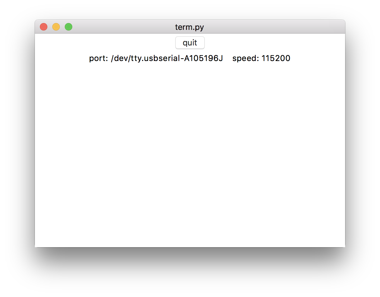
Look Ma, it's working!!

proof that my FabISP is working properly
My documentation wasn't convincing enough to prove that my FabISP worked properly. So I added a video below.
In the video, a button-and-blink program was initially running. I uploaded a simple blinking program, then to button-and-blink program again.
files
echo hello-world: EAGLE schematic (.sch)
echo hello-world: EAGLE PCB layout (.brd)
echo hello-world: traces image (.png)
echo hello-world: interior image (.png)
echo hello-world: traces toolpath for SRM-20 (.rml)
echo hello-world: interior toolpath for SRM-20 (.rml)