Mónica Pedro
Input Devices
Back to main page
Image
I need to use image as input data for my machines, and to start understand how it works, I will use an olde Raspberrypi 3 model B V1.2 that I already have
RASPBERRY PI 3 MODEL B because this board seams to have lots of examples online for camera's
Raspberry SetUp
Started to create an working set with:
- USB keyboard
- USB mouse
- HDMI screen
- Raspberry power supply
SD Card with the Raspbian Operating System, which impled:
- Download and install ETCHER
- Download the Zip file of Raspbian to my MAC from here Raspbian Doenloads
- Inserted the SD Card in my MAC
- Open ETCHER and select the ZIP file to go into the SD CARD
Raspian usefull Commands:
chech Raspbian OS version: cat etc/os-release
find files: find / -name xxxxxxname.extensionOfFileToSearchxxxxxx
Pi's IP Address: hostname -I
Raspian Remote Access using VNC - Virtual Network Computing
VNC (VIRTUAL NETWORK COMPUTING)
important steps:
- ON Raspbian: sudo apt-get update
- ON Raspbian: sudo apt-get install realvnc-vnc-server realvnc-vnc-viewer
- ON Raspbian(to activate Interface Option\VNC\Yes: sudo raspi-config
- ON Raspbian: hostname -I
- ON my MAC: call the VNC
- ON my MAC\VNC window: establish new connection withe Pi's IP
- ... and I can interact with Raspberry OS
Raspbian Hedless
to be able to program from my Mac....
VNC Server can create a virtual desktop, to provide me graphical remote access on demand. This virtual desktop exists only RaspberryPi's memory
- ON Raspbian run vncserver and note the IP address
- ON my MAC\VNC.app\create new connection: using the Pi's IP address
Camera on the Raspberry
I found this camera on the lab and decided to try it
for that I created a sccript on Raspbian terminal
USB CAM does not work anymore
I'd tried to use the FSWEBCAM command but got the error: stat: No such file or directory
looked online and tried: sudo modprobe bcm2835-v4l2... rumed and them fswebcam image.jog and got the same Error: stat !!!!
But... It was just UNPLUGED.... oHHHHH God
OpenCV on raspbian - for Edge detection
Fallowed the indications on Think RPI ~ Creative Raspberry Pi Area - Step 3 – Install softwares (for webcam and computer vision)
so I'd made the following in Console:
- sudo apt-get update
- sudo apt-get install guvcview
- sudo usermod -a -G video pi
- sudo modprobe uvcvideo
- sudo apt-get update
- sudo apt-get install cmake
- sudo apt-get update
- sudo apt-get install libopencv-dev
- sudo apt-get install python-opencv
- STOP here because the next step would be to test if OpenCV was whell installed using a C++ program, and I'd not yet worked with C programming
So changed the strategy and found a new possible path using Python
Edge Detection and OpenCv
but got some error's which seams to be related to Python Version and/or Raspbian Versio
I've installed on my R3 the Raspbian 9 named strech
I've installed the Python 3
... but the that code was written in Python2 grrrrrr!!!!!!
... so I'd to runn the code from the comand line: sudo python2.7 edge.py and it passes without any erros... IEE!!!!!
... but the windows doesn't show !!!!!
So lets back studing OpenCV fallowing this example: Adding a Trackbar to our applications!
I'll write the code using the Rasbpian Python 3 (IDE), but running the code from the comand Line with the comand sudo python2.7 NAMEANDEXTENSIONOFPYTHONFILE
it runned without erros... but now window apeared...
(-).(o)
_____________________________________________________________________
Python basics...
How to make a window with buttons in python
Python basics:
- "__init__' is the constructor of a class; the __init__ method gets called when memory for the object is allocated.
- self variable represents the isntance of the object itself. Most object-oriented languages pass this as an hidden parameter to the methods defined on an object; Python does not. We have to declare it explicitly. For instance when we cal the class A() simple without any arguments, Python creates an object, ans passes it as the first parameter to the __init__ method tip
Sensors connected to MYBOARD 01
I'll need to mey Final project these sensors:
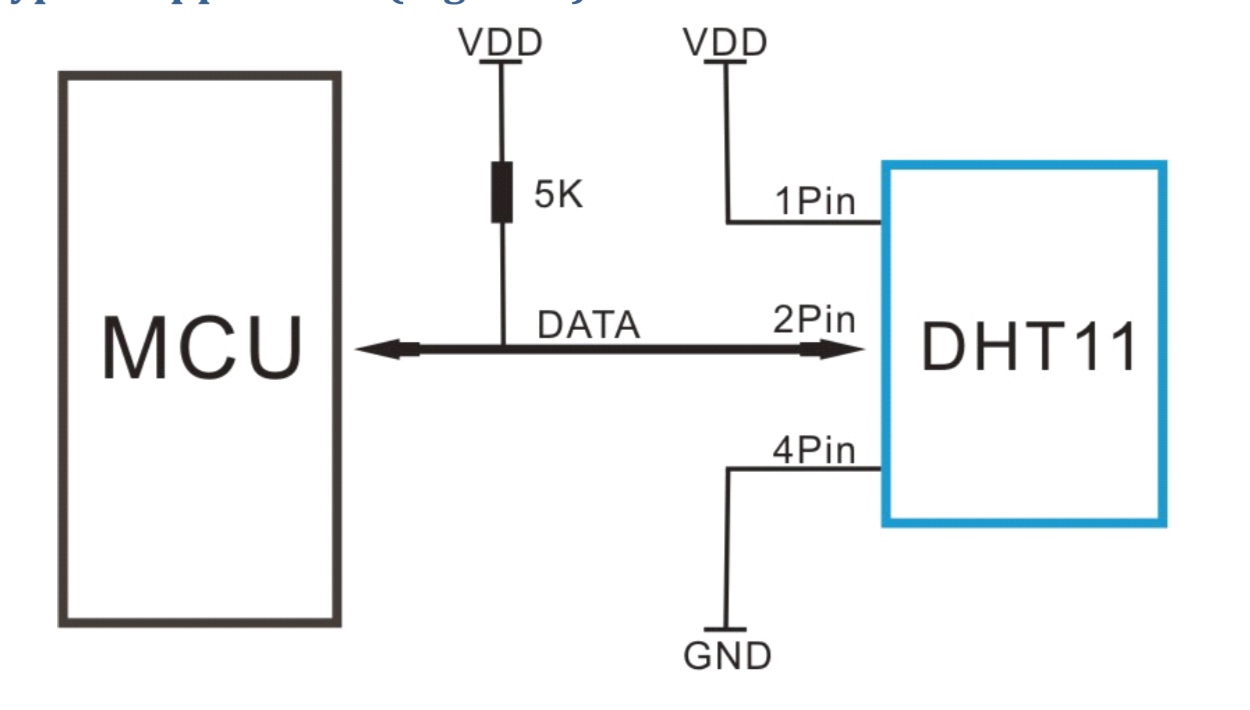
- Humidity and Temperature Sensor
- Power supply 3-5V DC: When power is supplied to the sensor, do not send any instruction to the sensor in within one second in order to pass the unstable status. One capacitor valued 100mF cab be added between VDD and GND for power fltering.
- Communication process: Serial interface (single-wire Two-Way: Single-bus data format is used for communication and suynchronization between MCU and DHT11 sensor. One communication process is about 4ms.
-
- Moisture Sensor
Instructables on those sensors...
Previews Students works for inspiration
Leire Bereziartua - Input Devices where he uses a Moisture sensor
Suhail - Input Devices where she uses a temperature + humidty + Infrared
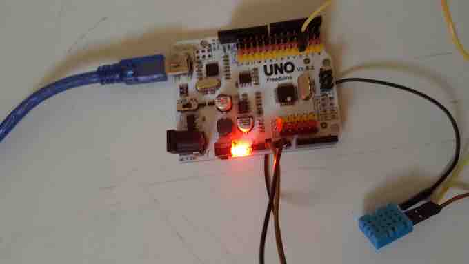
and to start playing with it through a ARduino UNO
the things I have in my home lab where:
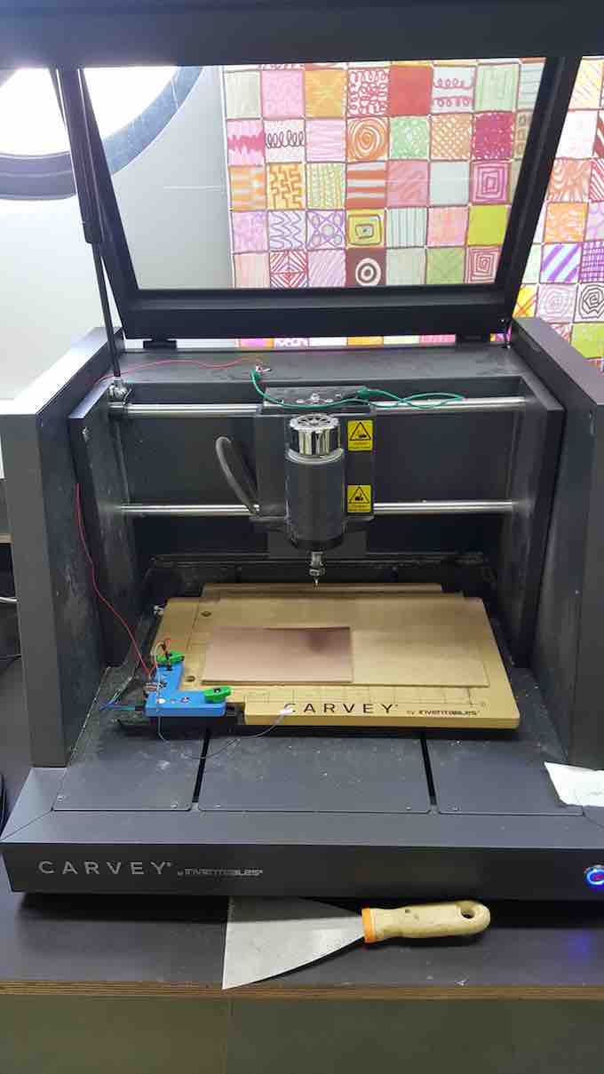
Practicing the Milling of boards
Milling at Carvey machine from Inventables
Carvey 3D carving machine - User Manual
......... preparing the files..... passes by
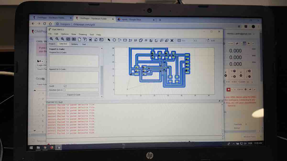
FlatCam - to prototype the PCB
FlatCAM: Free and Open-source PCB CAM
setps:
- after extracting all the files from Zip file made in Eagle , select the file (EAGLE layer) that will be sent to Milling
- in tab OPTIONS:
- ... PROJECT OPTIONS - define mm
- ... APPLICATION DEFAULTS - define mm
- if not doing the above FLatcam wil become strange
- having selected that layer in PROJECT tab goto Tab SELECTED and set
- .... Tool dia: 0.3
- .... Width (#passes): 3
- .... Pass overlap: 0.15000
- .... and GENERATE GEOMETRY
- back to PROJECT tab - select the new item _iso and goto tab SELECTED to set:
- .... Cut size: -0.6
- .... Travel Z: 2
- .... Feed Rate: 200.0
- .... Tool dia: 0.3
- .... Spindle-Depth: 14000
- .... and GENERATE
- select the new item in PROJECTS tb _cnc and go to tab SELECT to set:
- .... EXPORT GCODE, which will be file to Drag to Chilipeppr...
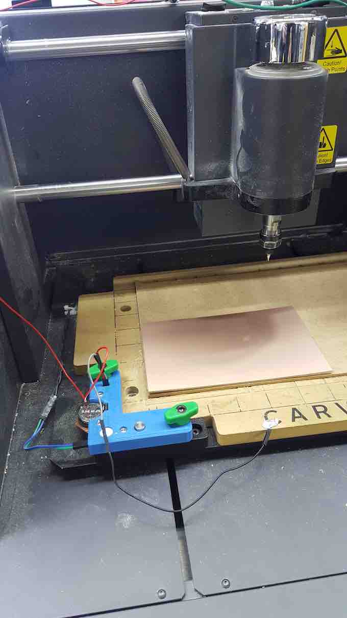
Chilipeppr
ChiliPeppr Hardware Fiddle
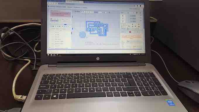
this is the program interfacing with the machine @ FCTFABLAB (Carvey from Inventables)
Steps
- drag the Gcode File (made through Flatcam)
- go out to windows file explorer window to connect the Serial port
- came back to Chilipepper
- Set the starting coordinates of the milling
- --using X, Y and Z buttons on left, move the mill head to the X,Y and X of Copper Board
- --when the light indicator on Milling machine is up...
- Set the Zero out and reset all: refres Chilipepper page, disconnect USB port on PC, and Electricity of Carbvey machine... them turn on PC-USB, Machine and refresh Chilipepper Page
- Test that the Zero is ok by: Lift up Z a lot
- click Go to Zero with close ATENTION to verify that it's realy going to the right position....
- .... if NOT - Quickly STOP the machine by removing the magnet on the door.. and resart all the positioning
- run AUTO-LEVEL that will map all the Z's of the board
- .... we can adjust the routing steps of auto-level
- once terminated the Auto-level,
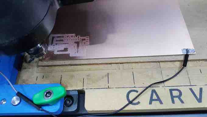
- RUN by clicking the button RUN, and here's it workong...
----------------------
after 4 tries... its not done... ERRRRRRRR
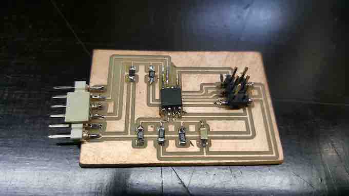
And after soldering with lots of care... here it is...
Preparation
XXXXXXXXxxx x x x x xxxxxx x x x x x x x x x:
Execution
Started by ..............................
 Creative Commons License