Output Device
01
Asigment
Individual Assignment:
add an output device to a microcontroller board you've designed, and program it to do somethingGroup Assignment:
measure the power consumption of an output device
Resource
Software
individual Assignment
03
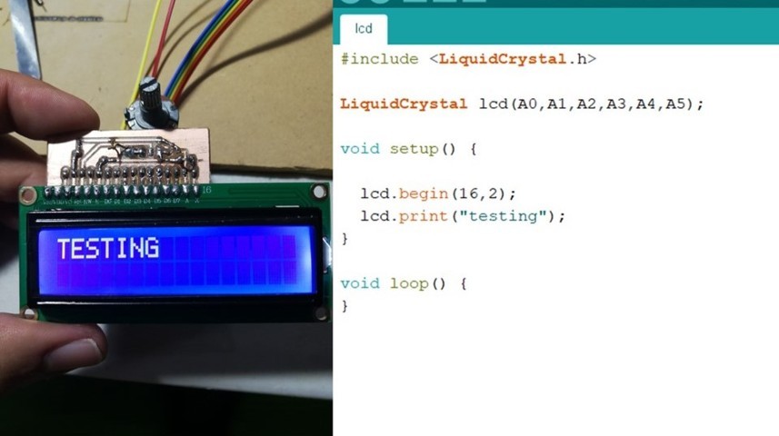
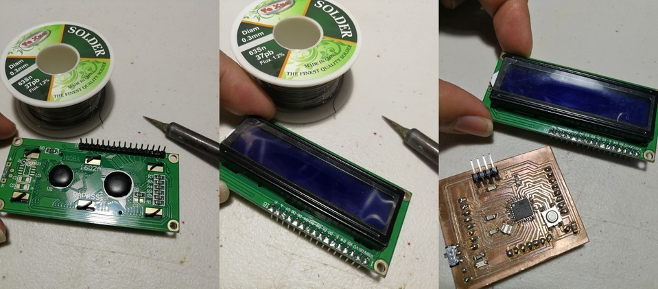
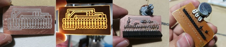
For this week output, I used an lcd so I made another Fabduino in the past week . lcd solder the pins to connect.
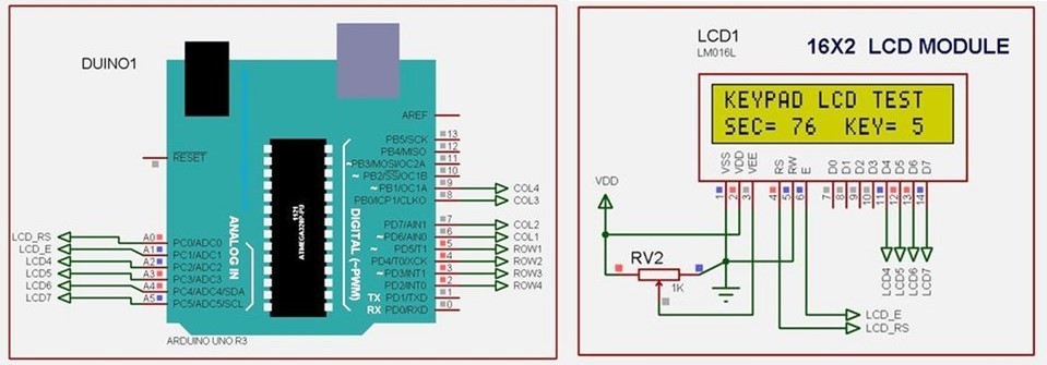
in the instructable tutorial. I've been guided by the connection diagram for an arduino.
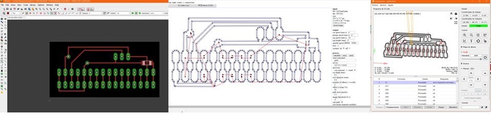
having the diagram as a guide I designed a plate in eagle since it contains a potentiometer and some jumper between pins and cut it.
once cut, verified, soldier we can make the connections to program them.
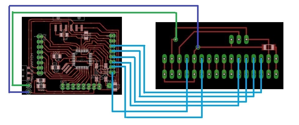
With this diagram that I made, this is where the lcd board should connect to the fabduino.
here I tried it with a breadboard after having the new board and soldier I tested the connectivity of the source.
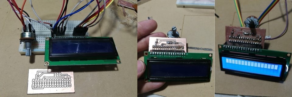
This is the code to show a test on the LCD. the potentiometer is for regulate the brightness backlight.