Computer Controlled Cutting
Assignment
Group:
-characterize your lasercutter, making test part(s) that vary cutting settings and dimensions
Individual:
-cut something on the vinylcutter
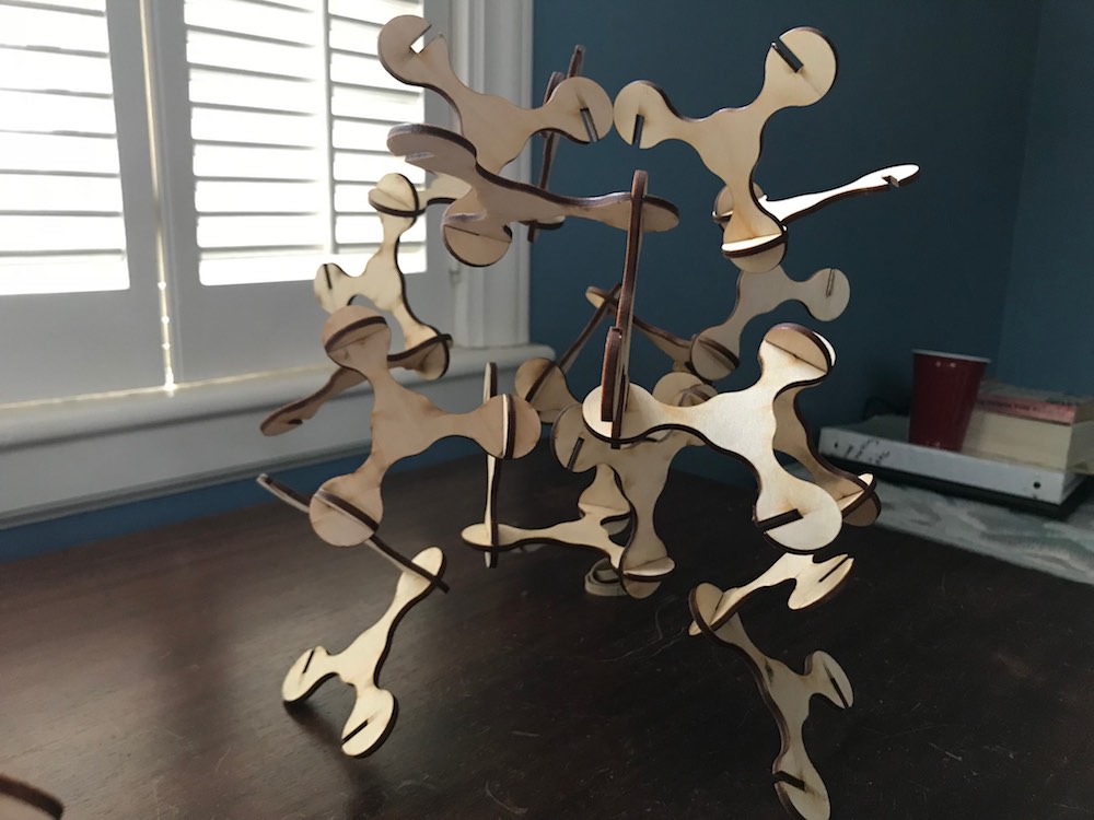
-design, lasercut, and document a parametric press-fit construction kit,
accounting for the lasercutter kerf, which can be assembled in multiple ways
Vinyl Cutting
I didn't have any exciting ideas for vinyl cutting this weekend, so I ended up just making a sticker for my computer and getting used to the workflow surrounding the vinyl cutter. The machines in our lab are the Silhouette Cameo Electronic Cutting Machine.
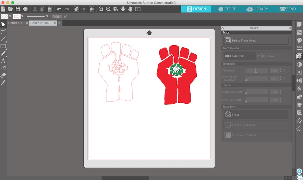
I chose an image from the internet (Hunter S. Thompson's campaign logo from his run for the sherrif of Aspen, Colorado) to make a sticker from. I was getting ready to open up Gimp or Inkscape to do some tracing when my classmate, Sarah, told me that I can do all of that in the Silhouette Studio software. The software was intuitive and simple to navigate. Tracing went smoothly. Everything was a breeze...and then the cutting began. I foolishly assumed the physical settings of the machine were correct, loaded my vinyl onto the cutting mat and into the machine, and pressed cut. A few seconds into the cut I saw a small birds' nest of vinyl forming around the cutter. Some of the small detail was destroyed, but the cut seemed to be continuing alright. When it finished and I tried to remove it from the cutting mat, I realized that the knife had been cutting all the way through the vinyl, the backing, and into the cutting mat. Whoops. I removed the knife and find it has been set to its full depth, 10! I consulted with another lab user that was more experienced with the vinyl cutters and found that the correct setting was closer to 3 or 4. With the correct settings dialed in all the cutting went smoothly. I used transfer tape to pull the vinyl I cut from the backing and place it on my computer.

Parametric Construction Kit
So for this project I wanted to challenge myself to continue using Grasshopper. At first I was just going to make a little construction kit modeled in Rhino with tabs that I'd be able to alter, but I instead opted for a fully parametric design solely in Grasshopper. I did this largely as a modeling challenge and to give me a chance to gain more familiarity with Grasshopper's unique environment.
Before we jump into the process, let me first say a few words about Grasshopper. If you don't know, it is a plug-in for the CAD program Rhino. It is a visual programming language that allows for parametric, algorithmic, and generative design within the Rhino environment. It can be a little intimidating to start using Grasshopper. I had a little bit of experience with it prior to this class, but mainly just tweaking settings on other people's files that I downloaded. There is a lot of support online for the program, and other users seem to be quite helpful in sharing their knowledge. I'll try to be one of those users, though I'm still learning a lot and often find I have to do things wrong a few times before I figure out how to use everything efficiently. More than once this week I've been working on a file and muddled it up so badly that it was easier to start over and fix my mistakes as I recreated everything than to attempt to correct the original. I learned a lot doing so and my files began to feel more orderly and organized. Check out below for some links to Grasshopper documentation online. >
Modeling
Number One
So this is the design I first imagined, sketching in Rhino:
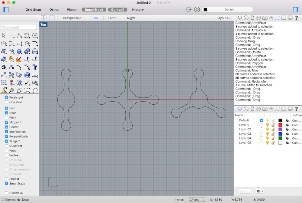
After a number attempts with Grasshopper that ended in frustration, I finally worked out some of the kinks and completed a model that resembled what I had initially imagined. The file is still a bit of a mess and as you'll see later, fails when outside of a certain working range.
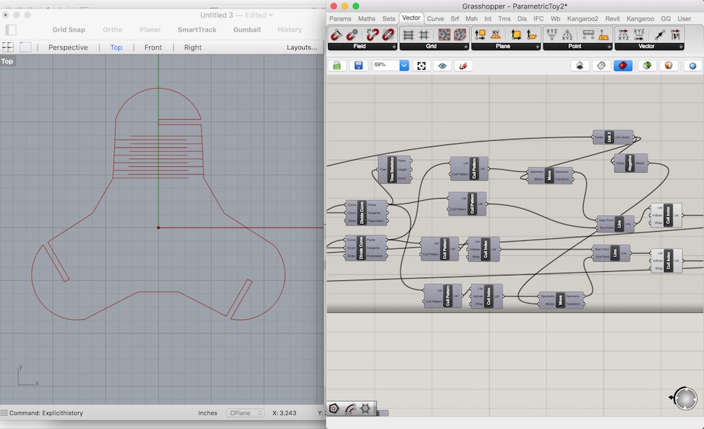
Here is a tour in the Grasshopper environment of my first complete working sketch:
And here is a video of me operating that file:
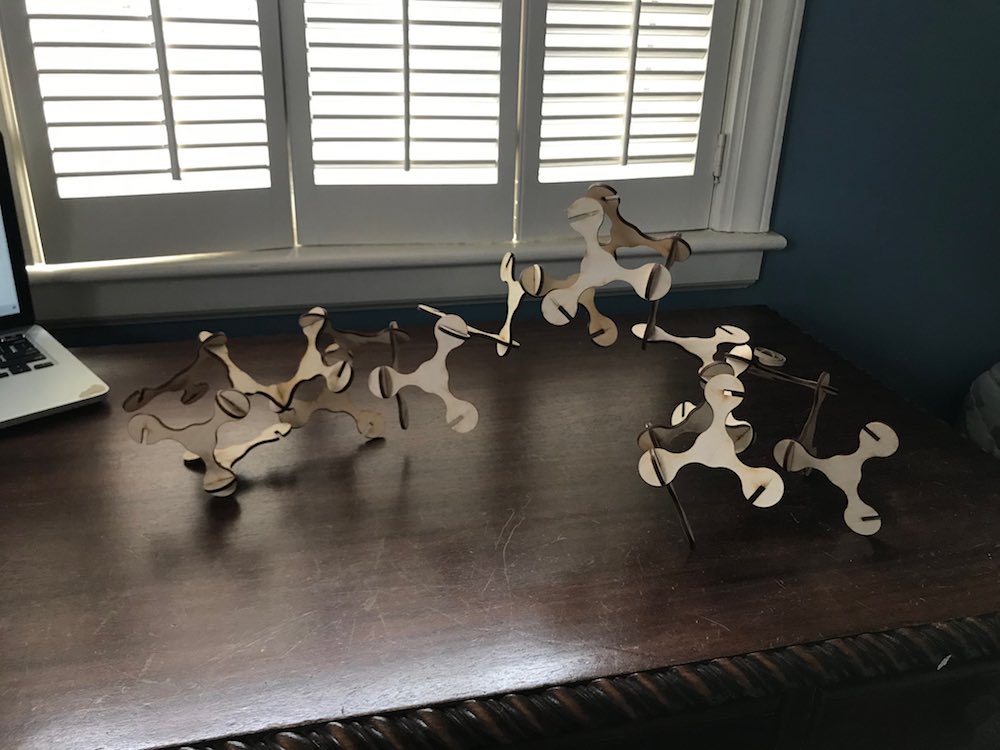
As you can see, the model "breaks" often when parameters do not match up and completely fails when anything other than a triangular array is selected. That being said, I did like the range of changes it allowed for, and settled on a version of the design that I liked the look of.
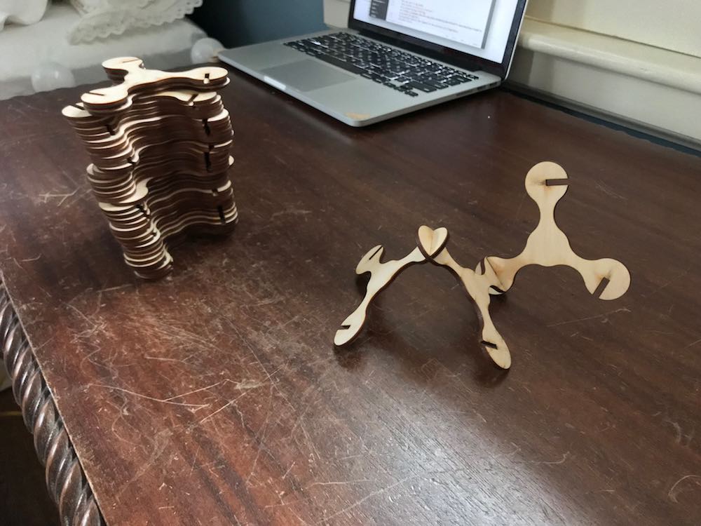
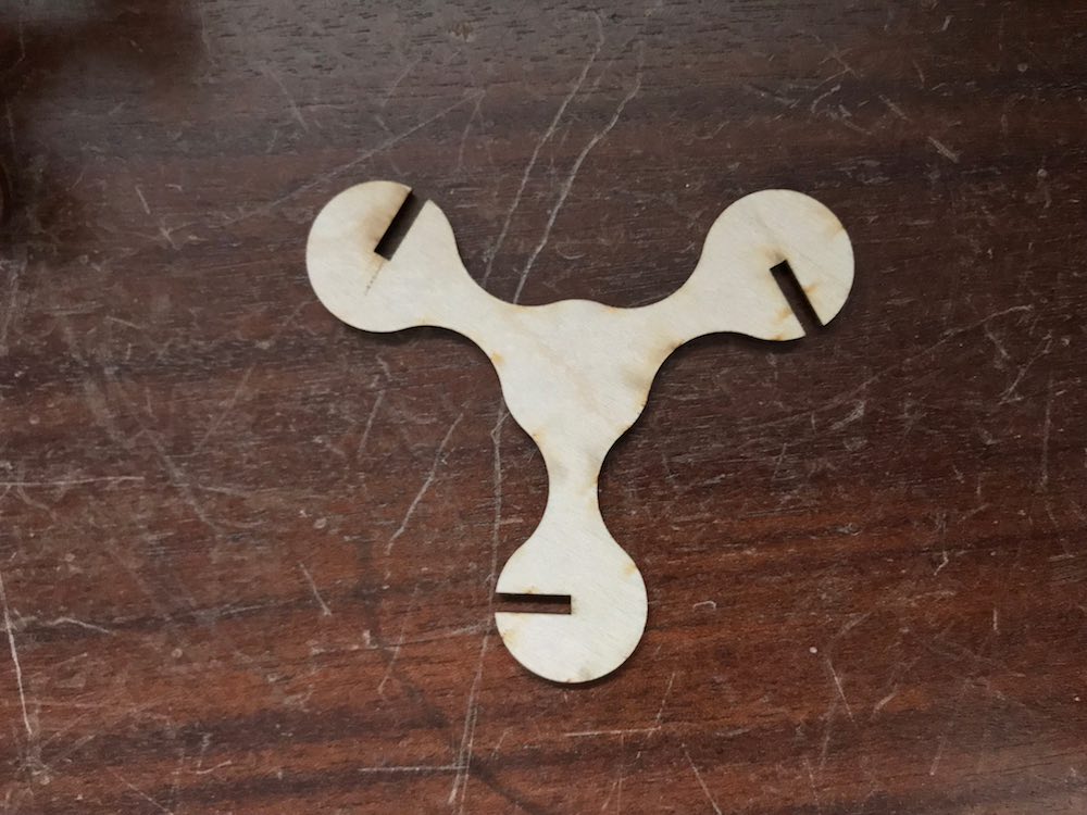
I transfered that geometry into Rhino with my slot width carefully selected. My material measured .125 inches and our laser produces a kerf approximately 10 thousandths of an inch, so I set the slot width to .115 for a tight interference fit.
I did end up using Rhino to array and arrange the pieces for layout on the laser engraver as you can see below
From Rhino, I exported the geometry as a DWG so that I could easily import it to CorelDraw, the program that the Lab uses for its laser engraver/cutter.
That's the end of the modeling part for this constuction kit
Number 2
So this idea came after cutting the first project and thinking about how to minimize waste and/or leave a functional offcut.
Number 3
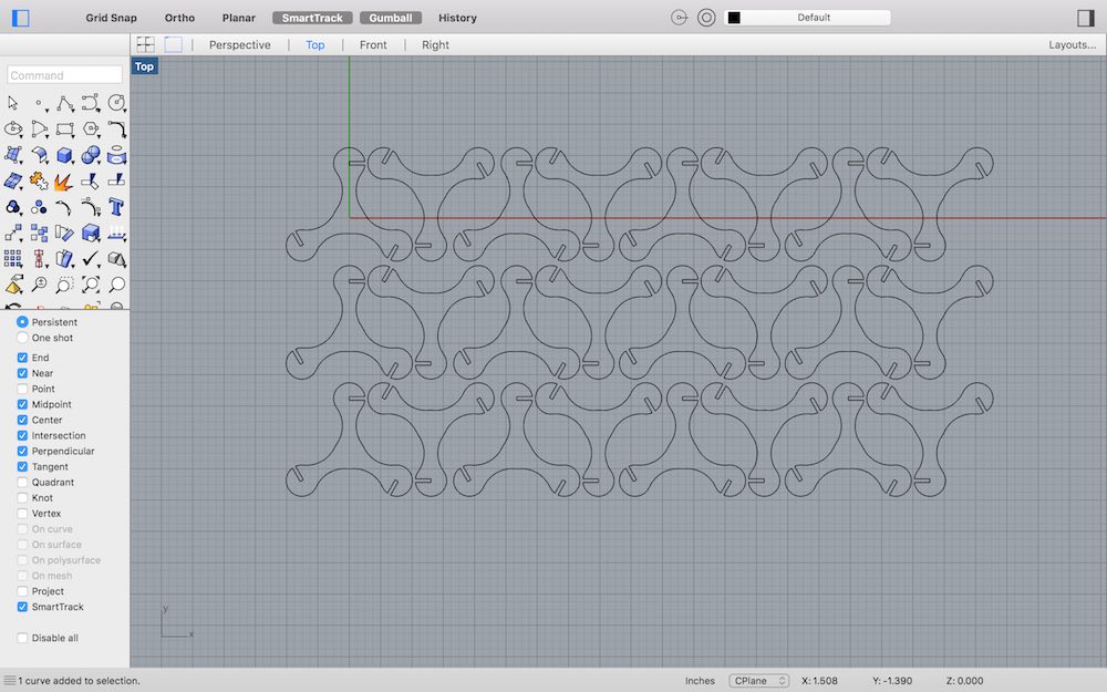
So after getting a tabbed grid to work for squares, triangles, and hexagons (the available stock grids in grasshopper), I wanted to go big and try for a grasshopper file that could make a range of tabbed tesselated shapes. I finally got the tesselation to work but only under certain circumstances, and it wasn't very pretty. I gave up on putting the tabs in. I'm sure that there is a way to better and more generally define a tesselation in grasshopper, but this one kinda works, and it was a learning experience making it.
Number 4
After the first few projects in Grasshopper, I was starting to feel more comfortable in the environment and wanted to try one more thing, to add flexible joints to the triangular construction toy. Creating the linework for these joints seems like something Grasshopper would be well suited to perform fairly efficiently
It actually was easier than I thought. I divided the lines that defined the arms of the object, offset those points from the the curve in the x direction, and connected the offset points to the original points on the opposite curve with lines.
Number 5
Last one. Got inspired by how easily and efficiently creating the joint lines worked. Decided to try to model a simple four sided pyramid shape with curved faces (there is probably a better name for that shape), unroll a flat surface from the faces, and parametrically define a joint pattern within the edge curves of that surface.
Pictures and videos to come!
Laser Cutting
To download my files click here: